MOTIVAIR MLC-SC-FC 0200 User manual

MOTIVAIR COOLING SOLUTIONS
85 Woodridge Dr. Amherst, NY 14228 –Phone# 716-691-9222 –Fax# 716-691-9229
www.motivaircorp.com
AIR COOLED CHILLERS
MODELS: MLC-SC-FC 0200 –MLC-SC-FC 1100
INSTALLATION, OPERATION, AND MAINTENANCE
MANUAL
This chiller has been factory run tested to the specified
water pressure
*****DO NOT OVER PRESSURIZE CHILLER WHEN LEAK
CHECKING PIPING OR FILLING HYDRAULIC SYSTEM*****
*Isolate chiller from piping if higher test pressure is
required for leak checking*
*Chiller damaged caused by over pressurization is NOT
covered by warranty*

LEGAL PROVISIONS & SAFETY INSTRUCTIONS
Operator's Responsibility This chiller MUST be installed, maintained and operated by a person(s)
qualified for this equipment. This chillercontains refrigeration, water
circulation and electrical components. The person(s) most suited for this
equipment is a qualified licenced refrigeration technician. Intervention by
unauthorized or unqualified parties may void the warranty.
WARNING
Operation of these systems involves potentially Iethal dangers (high
voltage and high pressures). Therefore, all safety precautions and
warnings described in this manual must be precisely observed.
Otherwise, severe or fatal injury may be caused.
SAFETY INSTRUCTIONS
The installation, start-up and maintenance of the chillers are
dangerous, Due to:
•High pressures is generated in the equipment
•Electrical parts are energized
•The equipment contains hot pipes (Refrigeration system)
•Rotating parts (fans and or pumps) can cause injury the chillers
themselves may be installed in a dangerous position (roof, high
built frame etc.)
For these reasons, the chiller must be installed and connected to the
electricity/water installations by qualified companies only. Startup and
maintenance must be conducted by a qualified refrigeration company
only.
Simple maintenance operations on the equipment without opening
them may be performed by the operator. All other work must be
performed by specially qualified personnel.

TRANSPORT AND HANDLING
LIFTING - UNLOADING – POSITIONING
Notices (symbols) –
on device packing must be
observed.
Check the center of gravity of the chiller.
Use appropriate unloading equipment.
Remove protective film from chiller and cardboard.
behind condenser before use.
MANUFACTURER'S NOTE
The machine may be damaged by:
Dropping or tipping it on the ground.
Pulling the chiller by cords, straps, etc.
Lifting the chiller by its piping system.
Excessive shaking by cranes.
Damage of this type is not covered by warranty.
ECA
ECA
MAX 45°
ECA
ECA

LIFTING - UNLOADING – POSITIONING
Notices (symbols) –
on device packing must be
observed.
Check the center of gravity of the chiller.
Use appropriate unloading equipment.
Remove protective film from metal panels before
use.
MANUFACTURER'S NOTE
The machine may be damaged by:
Dropping it or tipping it on the ground.
Pulling the chiller by cords, straps etc….
Lifting the chiller by its piping system.
Excessive shaking by crane.
Damage of this type is not covered by warranty.
H
HO
OO
OK
KI
IN
NG
G
T
TO
O
T
TH
HE
E
S
ST
TR
RU
UC
CT
TU
UR
RE
E
H
Ho
oo
ok
k
o
on
nl
ly
y
t
to
o
t
th
he
e
p
po
oi
in
nt
ts
s
i
in
nd
di
ic
ca
at
te
ed
d
b
by
y
t
th
he
e
l
li
if
ft
ti
in
ng
g
l
la
ab
be
el
ls
s.
.
M
Ma
ak
ke
e
s
su
ur
re
e
t
th
he
er
re
e
i
is
s
n
no
o
p
po
os
ss
si
ib
bi
il
li
it
ty
y
t
th
ha
at
t
t
th
he
e
h
ho
oo
ok
ks
s
c
ca
an
n
s
sl
li
ip
p
o
ou
ut
t
d
du
ue
e
t
to
o
s
sw
wi
in
ng
gi
in
ng
g
o
or
r
m
mo
ov
ve
em
me
en
nt
ts
s
f
fr
ro
om
m
t
th
he
e
c
cr
ra
an
ne
e
L
LI
IF
FT
TI
IN
NG
G
W
WI
IT
TH
H
A
A
C
CR
RA
AN
NE
E
U
Us
se
e
t
th
he
e
h
ho
ol
le
es
s
i
in
n
t
th
he
e
b
bo
ot
tt
to
om
m
f
fr
ra
am
me
ew
wo
or
rk
k
f
fo
or
r
l
li
if
ft
ti
in
ng
g.
.
T
To
o
d
di
is
st
tr
ri
ib
bu
ut
te
e
t
th
he
e
w
we
ei
ig
gh
ht
t
e
ev
ve
en
nl
ly
y
p
pl
la
ac
ce
e
a
a
s
st
tr
ro
on
ng
g
L
L-
-s
sh
ha
ap
pe
ed
d
s
se
ec
ct
ti
io
on
n
b
be
et
tw
we
ee
en
n
t
th
he
e
b
be
el
lt
ts
s
a
an
nd
d
s
st
tr
ru
uc
ct
tu
ur
re
e
w
wo
or
rk
k.
.
I
IN
NS
SE
ER
RT
T
S
SP
PR
RE
EA
AD
DE
ER
R
B
BA
AR
RS
S
T
TO
O
P
PR
RE
EV
VE
EN
NT
T
C
CR
RU
US
SH
HI
IN
NG
G
I
In
ns
st
ta
al
ll
li
in
ng
g
w
wi
it
th
h
a
a
f
fo
or
rk
k
l
li
if
ft
t
t
tr
ru
uc
ck
k
Use the forks to lift with: they must be as long
as the chiller. Use of fork extensions if
required, OR SERIOUS DAMAGE MAY RESULT.

Foundation
Site Installation
Installation
Structure-borne noise
Vibrations
Clearances
1. The condenser air is blown out vertically or horizontally.
2. Do not install the device close to heat sources. Heated air intake must be
avoided.
3. The condenser fans are rated for ZERO external static pressure. The fan
do not have the capacity to push air through ducting, which means that
NO DUCTS OR MUFFLERS may be used on the inlet ot outlet of the
chillers.
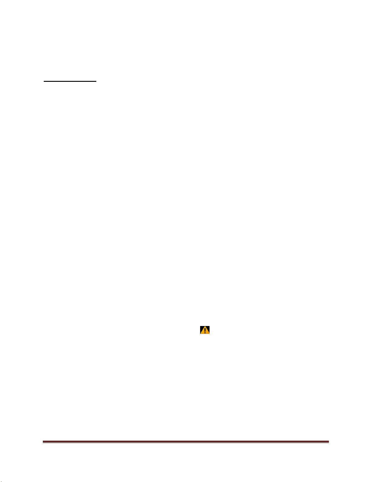
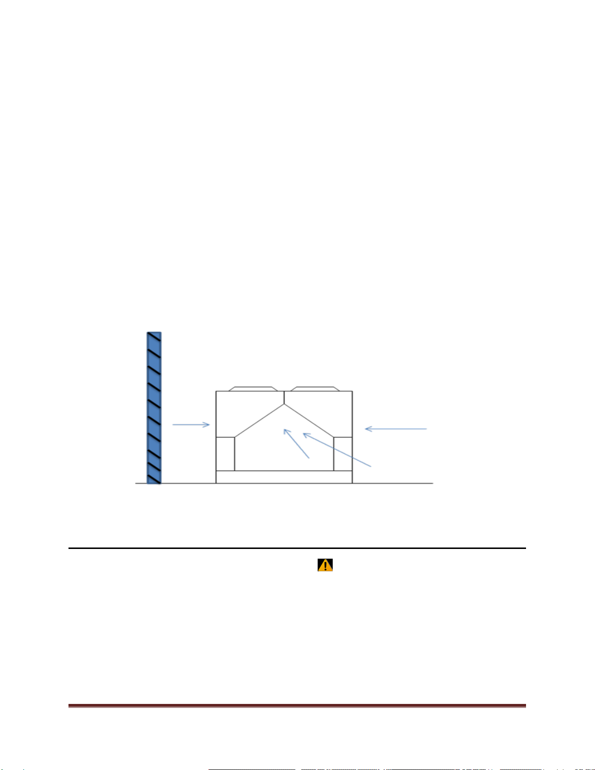
4. No air short-circuit is permitted, i.e. the heated discharge air from the
condenser fans must never be drawn back into the condenser inlet. This
will occur if the chiller is too close to a wall, or a low ceiling or other
obstructions.
5. In the case of shaft or trench mounting, contact the manufacturer for
advice on the installation site.
It ispossible thatnoise or vibration may betransmitted through the ground,
or building structure. If this occurs, it may benecessary toinstall a vibration
elimination device. The construction specifications ofthe
customer/engineering contractor regarding structure transmitted noise or
vibration must be observed.
May betransmitted through the chilled water piping. This can beavoided by
the use of flexible piping connections.
Must bemaintained for servicing and ventilation purposes. All removable
side panels must be available service.
*See CLEARANCE REQUIREMENTS section under MOTIVAIR INSTALLATION
ENGINEERING BULLETIN
CHILLER INSTALLATION
All chillers must be mounted ona solid, horizontal surface,suitable for the
weight of the chiller.* Note the chiller weight is incresed byfillingwith
glycol/water mixture.
Observe all local regulations.
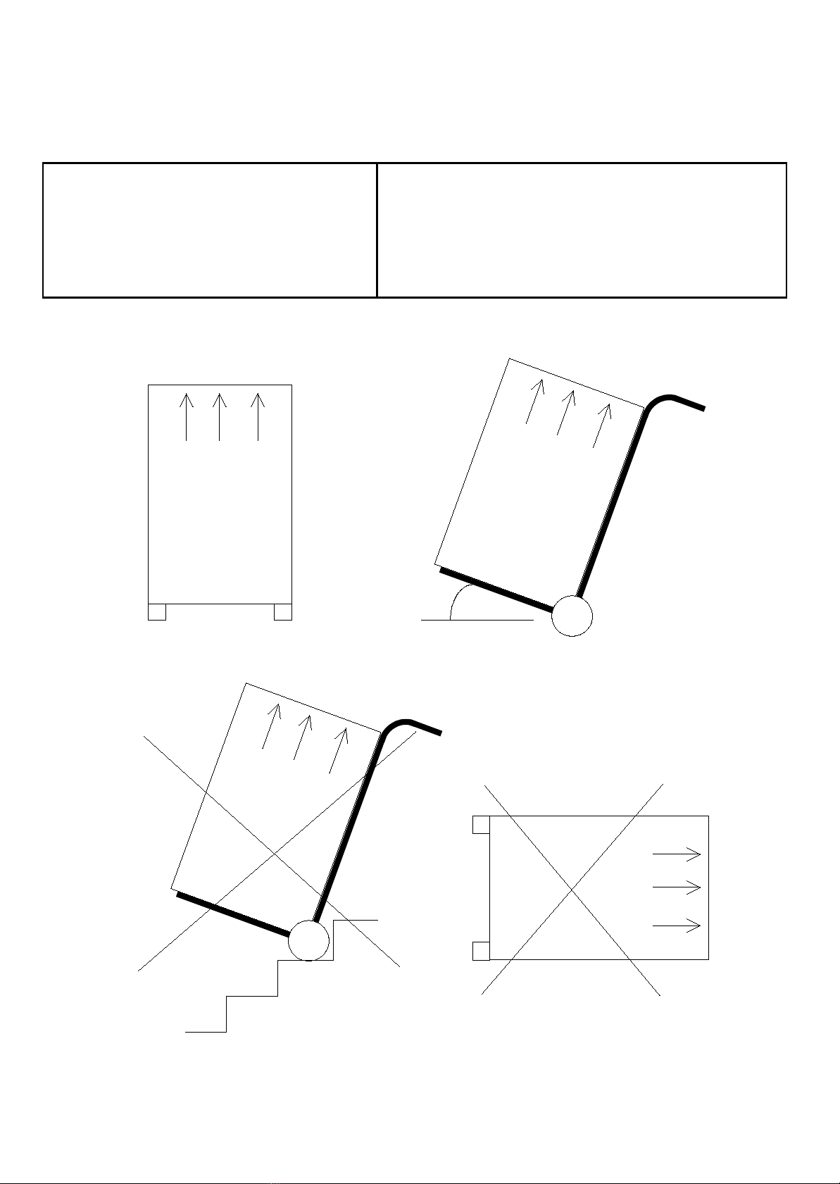
Compliance with the following basic rules for the erection ofdevices with
radial fans will ensure problem-free operation andthe rated refrigeration
capacity.
Basic rules:

Motivair Installation Guide Page 1
Motivair Installation Engineering Bulletin
Service Access:
Compressors, filter-driers, and manual liquid line shutoff valves are accessible on the front end
and both sides of the chiller. Each compressor (two) has its own contactors and overloads
mounted in the control box located in the front of the chiller. The main control box contains the
chiller PLC (Programmable Logic Controller). The solid state compressor starter, fan control
and other power equipment are located in the main control box. Condenser fan VFD’s and
overloads are located in an independent box on the side of the chiller. The side clearance
required for airflow provides sufficient service clearance.
On all MLC/MLC-FC condenser fan assemblies can be removed from the top of the unit for
service if necessary.
_____________________________________________________________________________
CAUTION
Disconnect all power to the chiller while servicing condenser fan motors or compressors.
Failure to do so can cause bodily injury or death.
______________________________________________________________________________
Do not obstruct access to the sides or ends of the chiller with piping or conduit. These areas
must be open for service access. Do not obstruct any access to the control panels with field
mounted disconnect switches. Make sure that the power conduit to each panel does not restrict
access to the filter-driers located between the compressors under the main control box.

Motivair Installation Guide Page 2
Clearance Requirements:
Figure 1
Notes:
1. Minimum side clearance between units is 12 feet (3.7 meters).
2. Unit must not be installed in a pit or enclosure that is deeper or taller than the height of the unit
unless extra clearance is provided per note 4.
3. Minimum clearance on each side is 8 feet (2.4 meters) when installed in a pit no deeper than the
unit height.
4. Minimum side clearance to a side wall or building taller than the unit height is 7 (2.1 meters) feet
provided no solid wall above 7 (2.1 meters) feet is closer than 12 (3.7 meters) feet to the opposite
side of the unit.
5. Do not mount electrical conduits where they can block service access to compressor controls,
refrigerant driers or valves.
6. There must be no obstruction of the fan discharge.
7. Field installed switches must not interfere with service access or airflow.
8. MLC/MLC-FC chillers use axial fans and are not suitable for ducted applications.
9. See the following pages if the airflow clearance cannot be met.
Restricted Airflow:
General
The clearances required for design operation of MLC/MLC-FC air-cooled condensers are
described in the previous section. Occasionally, these clearances cannot be maintained due to

Motivair Installation Guide Page 3
site restrictions such as units being too close together or a fence or wall restricting airflow, or
both.
The Motivair MLC/MLC-FC chillers have several features that can mitigate the problems
attributable to restricted airflow.
The “W” shape of the condenser section allows inlet air for these coils to come in from
both sides and the bottom. Facing the control cabinet, the right-side “V” condenser
serves the compressor on the right and vice versa for the left. Every compressor
always has its own independent refrigerant circuit.
The PLC control is proactive in response to off-design conditions. In the case of single
or compounded influences restricting airflow to the unit, the PLC will act to keep the
compressor(s) running (at reduced capacity) as long as possible, rather than allowing a
shut-off on high discharge pressure.
Figure 2
The following sections discuss the most common situations of condenser air restriction and give
capacity adjustment factors for each. Note that in unusually severe conditions, the PLC
controller would adjust the unit operation to remain online until a less severe condition is
reached.
CAUTION
The unit capacity adjustment charts in this engineering bulletin serve only as a guide, and DO NOT
take into account prevailing site conditions.
_____________________________________________________________________________________

Motivair Installation Guide Page 4
Case 1, Building or Wall on One side of One Unit:
The presence of a screening wall or the wall of a building, in close proximity to an air-cooled
chiller is common in both rooftop and ground level applications. Hot air recirculation on the
coils adjoining the wall increases compressor discharge pressure, decreasing capacity and
increasing power consumption.
When close to a wall, it is desirable to place chillers on the north or east side of them (to
minimize solar effect). It is also desirable to have prevailing winds blowing parallel to the unit’s
long axis. The worst scenario is having wind blowing hot discharge air into the wall.
Figure 3
Figure 4, Adjustment Factor

Motivair Installation Guide Page 5
Case 2, Two Units Side By Side:
Two or more chillers positioned side by side are common. If spaced closer than 12 feet it is
necessary to adjust the performance of each unit; circuits adjoining each other are affected. If
one of the two units also has a wall adjoining it, see Case 1. Add the two adjustment factors
together (Figure 4 and Figure 6) and apply to the unit between the wall and the other unit.
Mounting units end to end will not require adjusting performance. Depending on the actual
arrangement, sufficient space must be left between the units for access to the control panel door
opening and/or evaporator tube removal. See “Clearance” section of this guide for requirements
for specific units.
Pit or solid wall surrounds should not be used where the ambient air temperature exceeds 105°F.
Figure 5, Two Chillers Side by Side
Figure 6, Adjustment Factor

Motivair Installation Guide Page 6
Case 3, Three or More Units Side By Side:
When three or more units are side by side, the outside units (chillers 1 and 3 in this case) are
influenced by the middle chiller only on their inside circuits. Their adjustment factors will be the
same as Case 2. All inside units (only chiller 2 in this case) are influenced on both sides and
must be adjusted by the factors shown below.
Figure 7, Three or more Chillers
Figure 8, Adjustment Factor
Chiller 1
Chiller 2
Chiller 3

Motivair Installation Guide Page 7
Case 4, Open Screening Walls:
Decorative screening walls are common to help conceal a chiller either on grade or on a rooftop.
These walls should be designed such that the combination of their open area and distance from
the chiller do not require performance adjustment. It is assumed that the wall height is equal to,
or less than the chiller height when mounted on its base support. This is usually acceptable for
concealment. If the wall height is greater than the unit height, see Case 5 (Pit Installation).
The distance from the sides of the unit to the side walls should be sufficient for service and
opening control panel doors.
If each side wall is a different distance from the unit, the distances can be averaged, providing
either wall is not less than 8 feet from the unit. For example, do not average 4 feet and 20 feet to
equal 12 feet.
Figure 9, Open Screening Walls
Figure 10

Motivair Installation Guide Page 8
Case 5, Pit/Solid Wall Installation:
Pit installations can cause operating problems and great care should be exercised if they are to be
used on any installation. Recirculation and restriction are probable. A solid wall surrounding a
unit is effectively the same as a pit and the data given in Case 5 should be used.
Steel grating is sometimes used to cover a pit to prevent accidental falls or trips into the pit. The
grating material and installation design must be strong enough to prevent such accidents, yet
provide abundant open area or serious recirculation problems will occur. Have any pit
installation reviewed by Motivair application engineers prior to installation to discuss whether it
has sufficient airflow characteristics. The installation design engineer must approve the work
and is responsible for design criteria.
Figure 11, Pit Installation
Figure 12, Adjustment Factor

Motivair Installation Guide Page 9
System Volume Requirements:
Customer is responsible for insuring there is an adequate amount of system volume. Motivair
requires 3 to 5 times the amount of flow through the chiller at a minimum.
(Example: 5 min X 292 GPM At design conditions = 1,460 Gallons.)

PIPING INSTALLATION/RECOMMENDATIONS
This section is intended as a guide for the correct installation of the chilled water piping system,
including this chiller. However, the chiller manufacturer accepts no responsibility what so ever for the
installation of the chiller or the associated piping.
All piping must be installed only by a licensed plumbing contractor, and in compliance with local codes.
DO NOT USE GALVANIZED PIPING IF GLYCOL IS TO BE USED IN THE CHILLED WATER SYSTEM. Chemical
reaction between the glycol and the galvanized piping can be detrimental to the cooling system, the
glycol and chiller. Piping material may be copper, plastic, carbon or stainless steel depending on the
requirements of each installation.
It is the responsibility of the engineer and/or the piping contractor to insure that the piping is correctly
sized in relation to the installation, and the available dynamic head of the pump installed inside the
chiller. The chilled water pipe connections on the chiller are not necessarily the appropriate size for
the system piping. As a general guide, the chiller pipe connections should be considered as the
minimum pipe size required for the installation. Drastic reduction in pipe sizing (small hoses, etc.) will
reduce the chilled water flow and may cause a low flow alarm, or freezing damage to the evaporator.
Note: Installation with low water flow/high water temperature rise should always have a full-ported
by-pass installed between the chiller inlet and outlet connections, with a manually adjustable gate
valve in the by-pass line. Correctly adjusted, this blended return water will maintain an adequate flow
through the chiller, at an acceptable return temperature.
Always install a pressure gauge in the return piping close to the chiller. This is essential for monitoring
system pressure and pump performance.
It is recommended and also good piping practice, especially on systems with short piping runs and/or
low system pressure loss, to install a gate valve or balancing valve (i.e. triple duty valve or circuit
setter) in the DISCHARGE line from the chiller for throttling purposes. This allows the operator to
maintain optimum pump performance by adding resistance to the system. During system balancing
NEVER throttle the water flow on the return line to the chiller. This will cause cavitations and over-
heating of the pump.
CAUTION
ALWAYS INSTALL A FILTER/STRAINER ON THE INLET OF THE CHILLER, IN ORDER PREVENT
PARTICULATES (RUST, DIRT, INSTALLATION DEBRIS) FROM BLOCKING THE EVAPORATOR.
Blockage will severely impair chiller performance and is NOT covered by warranty.

AUTOMATIC WATER MAKE-UP
If the chilled water cooling system is expected to lose water during normal operation an automatic water
make-up system should be installed, or can be supplied as a factory option. The auto make-up system must
include a water pressure regulator and pressure gauge. CAUTION: The tank inside the chiller has a maximum
pressure rating of 45PSIG. Do not discharge city water (which can be 60-80psig) directly into the chiller.
Instantaneous pressurization can cause the tank to rupture before the pressure relief valve opens. NOTE: Do
not use an automatic water make-up system if glycol is installed for anti-freeze protection. The glycol will
become diluted and the freeze protection point will be higher (less protection from freezing). Some critical
applications require the installation of emergency city water and drain solenoid valves, in the event of a
chiller failure. In this case, the chiller MUST be isolated from the city water pressure to avoid damage. After
operation of the emergency city water system, the glycol concentration must be carefully checked using a
spectrometer. Add glycol to maintain the correct antifreeze concentration if required.
EXPANSION TANK
There is a small air space provided inside the top of the insulated reservoir of the chiller. This is designed to
act as a compression chamber, in order to absorb moderate hydraulic expansion of the water, during
operation. For systems with extensive piping, or large system chilled water volumes it is recommended to
install a closed diaphragm expansion tank in the return chilled water line, close to the chiller. The tank
should be sized using the appropriate calculations for the volume of water in the system, and the maximum
expected temperature fluctuation of the water in the piping system, under any conditions. The purpose of
the expansion tank is to absorb hydraulic expansion of the water in the system, which can cause damage to
the chiller, piping and/or equipment to be cooled. The expansion tank should be connected to the side of a
vertical pipe or the bottom of the horizontal return piping so that trapped air circulating in the chilled water
does not become trapped in the expansion tank. Expansion tanks are typically factory pre-charged with
compressed air to approximately 12-20 psig. After installation, filling & venting of the entire system, the
pressure of the expansion tank should be set to provide a pressure of 5-10 PSIG on the return side of the
chiller, with the chiller in operation. Air pressure can be added or removed from the diaphragm tank via the
Schraeder valve.
NOTE: Vertical piping immediately connected to and from the chiller will impose a static (or standing) head
pressure, which can be read on the pump discharge gauge of the chiller, and the gauge installed onthe
return line to the chiller, when the system is not operating. For example, if the supply and/or return piping
from the chiller rises 15 feet before running above a ceiling, etc. this will show a gauge static pressure of
approximately 6-7psig on the gauges (feet x .424 = psig). This is simply the weight of water in the vertical
piping at that location, and does not indicate an overall system pressure.
SYSTEM VENTING
The single most common problem in chiller piping installations is lack of chilled water flow caused by poor
piping practices and/or inadequate venting of the system. The symptom is a repeated flow alarm, when the
flow switch installed in the return line inside the chiller contacts open which in turns triggers the flow alarm
on the control panel.
This chiller is a CLOSED CIRCUIT system and is not open to atmosphere. This means that air will remain in all
local high points of the system when it is initially filled with water.
NOTE: A local high point is any point in the piping, which can be described as an inverted “U” section. More
clearly defined, if the piping rises vertically ANYWHERE, AND AT ANY ELEVATION IN THE SYSTEM, travels
horizontally, then drops again vertically, this inverted “U” section of piping IS A PERMANENT AIR LOCK AND
MUST BE VENTED. Venting is required AT ALL LOCAL HIGH POINTS, and is required on both the supply and
return pipes. Vents can be either manual, or automatic. Automatic vents should always be installed with an
isolation valve for future service access, repair or replacement. Automatic vents are particularly susceptible
to drawing air into the return chilled water piping if this line is allowed to fall into a vacuum.

1. Prevention of air being drawn into the system at vent locations close to the chiller, caused by
the pump drawing a vacuum in the return line.
2. Optimizing pump performance by providing a net positive suction head (N.P.S.H.) to the pump.
Positive system pressure can be imposed by carefully and slowly introducing city water pressure, via a
hose connection anywhere in the system. After the system has been completely filled and vented, note
the gauge pressure at the supply and return lines of the chiller. If there is no significant vertical piping
connected directly to the chiller, the gauges should be at zero. If a pre-pressurized expansion tank is
installed in the system, the initial system pressure should be approximately that of the expansion tank.
Start the chiller and observe the operating pressure on both the return and discharge water pressure
gauges. The return line to the chiller (while operating) should be enough to supply a N.P.S.H. The
discharge gauge on the chiller will be higher, depending on the pump, piping and system pressure losses
of each installation.
The return (or suction) pressure can be raised or lowered by carefully using city water pressure via a
hose connection, or by adjusting the diaphragm pressure of the expansion tank, or combination of both.
NOTE: The expansion tank should not normally be pressurized to more than 20psig, measured when the
system is not operating. The final discharge pump pressure should NEVER be allowed to exceed the
maximum pump rating pressure.
CAUTION: Supercharging the pump with city water pressure higher than nominal rating of the pump,
can damage the mechanical pump seal(s), or cause damage to the chiller, piping system or customer
equipment. This damage is not covered by the chiller warranty.
POSITIVE PRESSURIZATION OF THE SYSTEM
There are (2) reasons for positive pressure in a closed loop, pump piping system:

WATER/GLYCOL FILLING
If glycol is required for antifreeze protection, ALWAYS use an industrial inhibited ethylene glycol, or
propylene (food grade) glycol. DO NOT use automobile antifreeze. Suitable glycols are manufactured by
the Dow Chemical Company for this purpose, and available nationwide. There are other glycol suppliers
available, but always exercise great caution in the selection of a glycol supplier, and always confirm the
freeze protection after installation, using a spectrometer. Damage caused by freezing is not covered
under warranty.
Glycol can be pre-mixed with water to the correct concentration, then pumped into the system, or
pumped in separately from the water, provided the system capacity is calculated accurately. The most
common method for filling the system is to pump the water glycol into the fill or drain connection of
the chiller, with all system vents open. There is a manual vent located at the back of the chiller for
initial filling/venting purposes, in addition to the high point piping vents. NOTE: The system should be
filled slowly and carefully, allowing all the air to escape. The system can only be filled as fast as the air
can escape. Be patient, and do not over-pressurize the system. After initial operation, check all air is
vented from the system.
GLYCOL CHART
Ethylene Glycol Propylene Glycol
% of Glycol Freeze Point % of Glycol Freeze Point
0% 32F 0% 32F
10% 26F 10% 26F
20% 16F 20% 19F
30% 4F 30% 8F
40% -12F 40% -7F
50% -34F 50% -28F
60% -60F 60% -60F


WATER/GLYCOL INSTRUCTIONS
MANUFACTURER'S SPECIFICATIONS
The chiller circuit must be 100% filled with
water/glycol for operation. If the cooling process
causes a loss of water/glycol in the circuit a
automatic water make-up vavle must be installed.
Insufficient fluid in the water/glycol circuit wiIl lead to
malfunction of:
1. Safety devices
2. Controls,due to compressor fluctuations/ hunting
(frequent switching). And compressor starts.
3. Cooling Capacity
These can be avoided by adding a reservoir on the
inlet side of the chiller.
COLD WATER PIPING CONT.
6. Ensure that the water circuit is maintained at the
correct pressure by installing an appropriate sized
diaphragm expansion tank close to the inlet of the
chiller. The return side of the chiller must be 5-10psig
when the pump is running.
7. Install temperature and pressure gauges at the inlet
and outlet of the chiller and the heat load to ensure
easy inspection and maintenance.
8. All chilled water lines should be insulated. Only
insulate pipes AFTER the circuit was tested for leaks.
GLYCOL IN CIRCUIT
Glycol mixture
The following basic rules must be followed:
1. The freezing point of the mixture must be lower than
the minimum evaporation temperature. Or the
lowest outside piping temperature, whichever is the
lower of the two.
2. See correction factors for glycol concentration on
back page of the MPCA chiller brochure.
3. Use only an industrial grade inhibited ethylene glycol
or food grade propylene glycol solution. DO NOT use
automotive antifreeze.
4. Check the pH-value of the solution. lt should be
about 9 and must never be less than 7.5.
5. Check the pH-value regularly (maintenance).
6. DO NOT use galvanized piping or fittings
Operating the devices with a glycol mixture
Check the extemal cold water network and pumps:
sufficient pressure for increased water volume
pumps suitable for glycol operation
bleed valves (rapid bleeder unsuitable)
IMPORTANT: NEVER change the antifreeze alarm
parameter on chiller without written authorization from
factory. If parameter is changed withour factory consent
WARRANTY WILL BE VOIDED.
!!!WARNING!!!
The glycol/water mixture must not be discharged into
the normal water drainage system. lt must be
collected in suitable containers and disposed of in
accordance with legal regulations.
OnIy operate the chiller with a flow switch
(supplied) that switches off the chiller in the event
of insufficient water or a faulty pump.
If this condition is not satisfied:
ALL WARRANTY CLAIMS SHALL BE VOIDED
Flow meter and a automatic water make-up system
can be purchased from the factory.
COLD WATER PIPING
Water piping and connection to the chiller must
conform with all generally accepted piping practices
and local codes. All piping should be performed by a
qaulified person(s) or company.
The following specifications are intended to prevent
damage to the chiller.
1. Avoid unnecessary pressure drop by ensuring
correct pipe sizes and routing.
2. Connect the chiller with vibration eliminators to
avoid transmission of noise and vibrations.
3. Shut-off valves should be installed at the inlet and
outlet of the chiller so that maintenance and
repair work can be performed without draining
the piping system.
4. Y-Strainer (40 mesh) should be installed on the
inlet piping to the chiller to ensure no foreign
particles enter the evaporator and or
pump.*Without a Y-Strainer installed blockage
of the evaporator will occur
5. Automatic vents should be installed at all local
high points of the piping system to eliminate air
locks. See chilled water system diagram for
location(s).
This manual suits for next models
1
Table of contents
Popular Chiller manuals by other brands

Trane
Trane Sintesis RTAF Installation, operation and maintenance

ICS
ICS iC 215 Operating and maintenance manual

Attila
Attila GN2 User and maintenance manual

York
York YHAU-CL Series Installation operation & maintenance

Daikin
Daikin WGZ030DW Installation and maintenance manual

Aquaport
Aquaport AQP-BRD User manual & warranty

Carrier
Carrier 16DF013-050 installation instructions

York
York MILLENNIUM YCAS0373 Wiring diagram

Hoshizaki
Hoshizaki Lancer Superchiller Remote R8E V2 Series Installation, operation & service manual

AIREDALE
AIREDALE LogiCool InRak Technical manual

York
York YCRS Series Installation, operation and maintenance

Master Bilt
Master Bilt MCR-33-101 Specifications