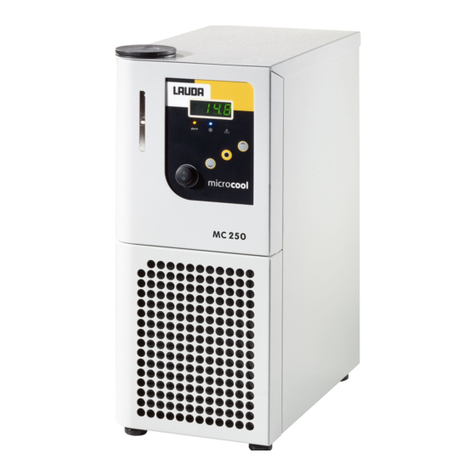
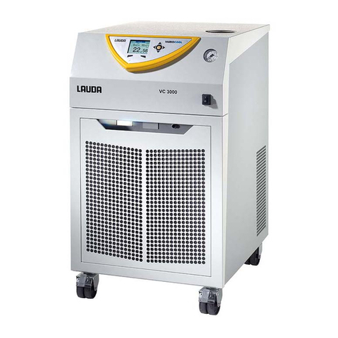
Lauda VC 1200 User manual

Variocool
VC 1200 (W), VC 2000 (W), VC 3000 (W), VC 5000 (W), VC 7000 (W), VC 10000 (W)
Operation manual
Circulation chiller
V8R8Read this manual prior to performing any task!

replaces issue V7R11, V7R10, V7R7, V6R17, V5R19, V5R18, V5R16, V5R12, V5R05, V4R22, V3R101, V3R100
1/17/2022
Translation of the original operation manual
LAUDA DR. R. WOBSER GMBH & CO. KG
Laudaplatz 1
97922 Lauda-Königshofen
Germany
Telephone: +49 (0)9343 503-0
Fax: +49 (0)9343 503-222
E-mail: [email protected]
Internet: https://www.lauda.de
V08Variocool2 / 97
Q4WA-E_13-002, 8, en_US ©LAUDA 2012

Table of contents
1 Safety...................................................................................................................................................................................... 7
1.1 General safety instructions........................................................................................................................................... 7
1.2 Observing additional operating instructions............................................................................................................... 7
1.3 Intended Use.................................................................................................................................................................. 8
1.4 Foreseeable misuse....................................................................................................................................................... 8
1.5 EMC requirements....................................................................................................................................................... 8
1.6 Software versions.......................................................................................................................................................... 9
1.7 Prohibition of modifications to the device................................................................................................................. 9
1.8 Requirements for the heat transfer liquid.................................................................................................................. 9
1.9 Materials......................................................................................................................................................................... 9
1.10 Hose requirements...................................................................................................................................................... 10
1.11 Application area........................................................................................................................................................... 10
1.12 Personnel qualification................................................................................................................................................ 10
1.13 Personal protective equipment.................................................................................................................................. 10
1.14 Product safety label...................................................................................................................................................... 11
1.15 Structure of warnings................................................................................................................................................... 11
2 Unpacking............................................................................................................................................................................. 13
3 Device description............................................................................................................................................................... 14
3.1 Device types................................................................................................................................................................. 14
3.2 Setup of the device...................................................................................................................................................... 15
3.3 Operating elements..................................................................................................................................................... 17
3.3.1 Mains switch............................................................................................................................................... 17
3.3.2 Display buttons......................................................................................................................................... 18
3.4 Functional elements.................................................................................................................................................... 18
3.4.1 Hydraulic circuit........................................................................................................................................ 18
3.4.2 Cooling unit............................................................................................................................................... 19
3.4.3 Interfaces................................................................................................................................................... 19
3.5 Equipment..................................................................................................................................................................... 21
3.6 Type plate..................................................................................................................................................................... 22
4 Before starting up................................................................................................................................................................ 23
4.1 Installation.................................................................................................................................................................... 23
4.2 Connecting the consumer......................................................................................................................................... 24
4.2.1 Thermostatic hoses and hose clips......................................................................................................... 24
4.2.2 Connecting an external consuming unit............................................................................................... 25
4.3 Cooling water............................................................................................................................................................... 26
4.3.1 Cooling water requirements................................................................................................................... 26
4.3.2 Connecting the cooling water................................................................................................................. 27
V08 Variocool 3 / 97

4.4 Interfaces..................................................................................................................................................................... 28
4.4.1 Interface potential-free contact............................................................................................................ 28
4.4.2 Installing interface modules.................................................................................................................... 29
5 Commissioning.................................................................................................................................................................... 30
5.1 Heat transfer liquids................................................................................................................................................... 30
5.2 Establishing power supply........................................................................................................................................... 31
5.3 Switching on the device for the first time and filling with liquid............................................................................. 31
5.3.1 Fill mode..................................................................................................................................................... 31
5.3.2 Switch on the device and fill it................................................................................................................ 33
5.4 Setting the pump pressure........................................................................................................................................ 34
6 Operation............................................................................................................................................................................. 36
6.1 General safety instructions........................................................................................................................................ 36
6.2 Operating modes........................................................................................................................................................ 36
6.3 Menu structure overview............................................................................................................................................ 37
6.4 Switching on the device.............................................................................................................................................. 39
6.5 The display.................................................................................................................................................................... 39
6.5.1 Home window........................................................................................................................................... 39
6.5.2 Menu window........................................................................................................................................... 40
6.5.3 Entry window............................................................................................................................................. 41
6.5.4 Lock and release operating buttons....................................................................................................... 42
6.6 Define temperature limits.......................................................................................................................................... 43
6.7 Specifying the set point............................................................................................................................................. 44
6.8 Activating and deactivating standby......................................................................................................................... 44
6.9 SmartCool (cooling)................................................................................................................................................... 44
6.10 External control........................................................................................................................................................... 45
6.10.1 Activating the external control............................................................................................................... 45
6.10.2 Specifying the set point oset............................................................................................................... 46
6.11 Control......................................................................................................................................................................... 47
6.11.1 Basics......................................................................................................................................................... 47
6.11.2 Opening the control menu..................................................................................................................... 49
6.11.3 Overview of internal control parameters.............................................................................................. 50
6.11.4 Adapting internal control parameters................................................................................................... 50
6.11.5 Overview of external control parameters.............................................................................................. 51
6.11.6 Adjusting external control parameters.................................................................................................. 52
6.12 Basic settings............................................................................................................................................................... 53
6.12.1 Calling the basic settings......................................................................................................................... 53
6.12.2 Adjusting the volume of the signal tones.............................................................................................. 53
6.12.3 Adjusting the display brightness............................................................................................................. 53
6.12.4 Specifying the starting mode (Auto start)............................................................................................ 54
V08
Variocool4 / 97

6.12.5 Limiting the current consumption......................................................................................................... 55
6.12.6 Configuring the alarm level for the fill level.......................................................................................... 55
6.12.7 Setting the alarm output......................................................................................................................... 56
6.12.8 Selecting the menu language................................................................................................................. 56
6.13 Entering the oset of the internal actual temperature (calibration)..................................................................... 57
6.14 Restoring the factory calibration (internal temperature probe)............................................................................ 57
6.15 Restore factory setting.............................................................................................................................................. 58
6.16 Device status............................................................................................................................................................... 59
6.16.1 Viewing the device status........................................................................................................................ 59
6.16.2 Reading the Error store........................................................................................................................... 59
6.16.3 Retrieving device data............................................................................................................................. 60
6.16.4 Retrieving the software version............................................................................................................. 60
6.16.5 Displaying device type............................................................................................................................ 60
6.16.6 Displaying serial numbers......................................................................................................................... 61
6.17 Programmer.................................................................................................................................................................. 61
6.17.1 Program example...................................................................................................................................... 61
6.17.2 Selecting the program............................................................................................................................. 64
6.17.3 Create and edit programs....................................................................................................................... 64
6.17.4 Defining program loops........................................................................................................................... 66
6.17.5 Starting, interrupting and ending a program......................................................................................... 67
7 Maintenance........................................................................................................................................................................ 68
7.1 General safety instructions........................................................................................................................................ 68
7.2 Maintenance intervals................................................................................................................................................ 68
7.3 Cleaning the device.................................................................................................................................................... 69
7.4 Checking the low-level protection........................................................................................................................... 69
7.5 Cleaning the air-cooled condenser.......................................................................................................................... 70
7.6 Cleaning the water filter............................................................................................................................................. 70
7.7 Descale cooling water circuit...................................................................................................................................... 71
7.8 Check the heat transfer liquid................................................................................................................................... 72
8 Faults.................................................................................................................................................................................... 73
8.1 Alarms, errors and warnings....................................................................................................................................... 73
8.2 Alarm codes................................................................................................................................................................. 73
8.3 Low level alarm............................................................................................................................................................. 74
8.4 Overtemperature alarm.............................................................................................................................................. 74
8.5 Warnings - control system......................................................................................................................................... 75
8.6 Warnings – safety system.......................................................................................................................................... 76
8.7 Warnings - SmartCool................................................................................................................................................ 77
9 Decommissioning................................................................................................................................................................ 79
9.1 Drain the device.......................................................................................................................................................... 79
V08 Variocool 5 / 97

9.2 Draining the condenser.............................................................................................................................................. 79
10 Disposal................................................................................................................................................................................. 81
10.1 Disposing of refrigerant............................................................................................................................................... 81
10.2 Device disposal............................................................................................................................................................. 81
10.3 Disposing of packaging................................................................................................................................................ 81
11 Technical data...................................................................................................................................................................... 82
11.1 General and type-specific data................................................................................................................................. 82
11.2 Cooling capacity......................................................................................................................................................... 84
11.3 Refrigerant and filling quantity.................................................................................................................................. 85
11.4 Filling volume and characteristics of the pumps..................................................................................................... 85
11.5 Heater (potential equipment)................................................................................................................................... 88
11.6 Potential equipment, voltage-independent............................................................................................................. 89
11.7 Line fuse....................................................................................................................................................................... 89
12 Accessories.......................................................................................................................................................................... 90
13 General.................................................................................................................................................................................. 91
13.1 Copyright...................................................................................................................................................................... 91
13.2 Technical changes........................................................................................................................................................ 91
13.3 Warranty conditions.................................................................................................................................................... 91
13.4 Contact LAUDA......................................................................................................................................................... 91
13.5 Declaration of Conformity......................................................................................................................................... 91
13.6 Product Returns and Clearance Declaration.......................................................................................................... 93
14 Index..................................................................................................................................................................................... 94
V08
Variocool6 / 97

1 Safety
1.1 General safety instructions
nThe devices must only be operated for the intended purpose under the
conditions stated in this operating manual. Any other operating mode
is considered to be non-intended use and can impair the protection
provided by the device.
nThe devices are not designed for use under medical conditions in
accordance with DIN EN 60601-1 or IEC 601-1!
nThe operating manual is a constituent part of the device. The information
in this operating manual must therefore be available in the immediate
vicinity of the device. Also take care to keep this copy of the operation
manual.
If you lose this operating manual, contact the LAUDA Constant
Temperature Equipment service department. The contact details can
be found in ÄChapter 13.4 “Contact LAUDA” on page 91.
Use of the device results in hazards from high and low temperatures and
from the use of electrical energy. The hazards arising from the device have
been eliminated as far as possible by the design in accordance with the
applicable standards. Residual hazards are reduced using any of the following
measures:
nIf relevant, there are safety fittings for the device. These devices are
essential for the safety of the device. Their functionality must be
ensured by carrying out the appropriate maintenance activities.
The safety fittings of the device are described in this "Safety" chapter.
nIf relevant, there are warning symbols on the device. These symbols must
always be observed.
The warning symbols on the device are described in this "Safety" chapter.
nThere are safety instructions in this operating manual. These instructions
must always be observed.
nThere are additional specific requirements for the sta and for the
personal protective equipment.
These requirements are described in this "Safety" chapter.
An overview of the authorised personnel and the protective equip-
ment can be found in ÄChapter 1.12 “Personnel qualification”
on page 10 and ÄChapter 1.13 “Personal protective equip-
ment” on page 10.
Further information about the general structure of safety instruc-
tions can be found in ÄChapter 1.15 “Structure of warnings”
on page 11.
1.2 Observing additional operating instructions
Additional interface modules can be fitted to the device. Before installing
and using interface modules, always read and observe the operating manual
accompanying the relevant interface module.
Interface modules
V08 Variocool 7 / 97

1.3 Intended Use
The present device is exclusively permitted to be used for tempering and
delivering non-flammable heat transfer liquids in a closed circuit.
The following applications are considered to be non-intended:
nin potentially explosive areas
nfor tempering foodstus
nwith a glass reactor without overpressure protection
1.4 Foreseeable misuse
Misuse of the device must always be prevented.
Among other things, the following uses are considered to be foreseeable
misuse:
nOperation of the device without heat transfer liquid
nIncorrect connection of hoses
nSetting the device up on a tabletop surface
nSetting an incorrect pump pressure
1.5 EMC requirements
Table 1: Classification in accordance with EMC requirements
Device Interference immunity Emissions class Customer power supply
Variocool Type 2 in accordance
with DIN EN 61326-1 Emissions Class B in
accordance with CISPR 11
Only for EU
Domestic connection value
³100 A
Variocool Type 2 in accordance
with DIN EN 61326-1 Emissions Class B in
accordance with CISPR 11
Rest of the world (outside EU)
No limitation
"This equipment has been tested and found to comply with the limits for
Class A digital device, pursuant to Part 15 of the FCC (Federal Communica-
tion Commission) Rules. These limits are designed to provide reasonable
protection against harmful interference when the equipment is operated in a
commercial environment. This equipment generates, uses, and can radiate
radio frequency energy and, if not installed and used in accordance with the
instruction manual, may cause harmful interference to radio communica-
tions. Operation of this equipment in a residential area is likely to cause
harmful interference in which case the user will be required to correct the
interference at his own expense."
“This Class A digital apparatus complies with Canadian ICES-003” (ICES =
Interference Causing Equipment Standards).
« Cet appareil numérique de la classe A est conforme à la norme NMB-003
du Canada ».
Intended Use
Non-intended use
Instructions for Class A digital device, USA
Instructions for Class A digital device,
Canada
V08Variocool8 / 97

1.6 Software versions
These operating instructions are valid for devices using the following software
versions onwards.
Software valid from version
Command operating system 3.45
Control system 1.35
Analogue IO module 3.24
RS 232/485 module 3.22
Digital IO module 3.14
External temperature module 1.35
Ethernet module 1.23
EtherCAT module 1.06
1.7 Prohibition of modifications to the device
Any technical modification of the device by the user is prohibited. Any
damage resulting from unauthorized modification is not covered by customer
service or the product warranty. Service work may only be performed by the
LAUDA Service department or a service partner authorized by LAUDA.
1.8 Requirements for the heat transfer liquid
nHeat transfer liquids are used to control the temperature. LAUDA heat
transfer liquids are recommended for the constant temperature equip-
ment. LAUDA heat transfer liquids have been tested by the company
LAUDA DR. R. WOBSER GMBH & CO. KG and approved for this
device.
nThe heat transfer liquids are suitable for a specific temperature range.
This temperature range must correspond with the temperature range of
your application.
nHazards caused by high or low temperatures or fire may arise during
operation if the heat transfer liquid exceeds or falls below certain tem-
peratures or if the container ruptures causing a reaction with the heat
transfer liquid.
nThe safety data sheet of the heat transfer liquid specifies hazards and
the corresponding safety measures required for handling the liquid. The
safety data sheet of the heat transfer liquid must therefore be observed
to ensure proper use of the device.
nIf you wish to use your own heat transfer liquids, check to ensure that
the fluids are compatible with the materials used.
nThe heat transfer liquid must be provided with corrosion protection.
1.9 Materials
All parts that come into contact with heat transfer liquid are manufac-
tured from high-quality materials adapted to withstand the operating tem-
perature. High-quality stainless steels, copper, brass and premium-quality
heat-resistant plastics are used.
V08 Variocool 9 / 97

1.10 Hose requirements
The hoses for the external hydraulic circuit must be resistant to:
nthe heat transfer liquid used
nthe pressure in the hydraulic circuit
nthe high and low working temperatures
1.11 Application area
The device is exclusively permitted to be used in the following areas:
nCommercial sector
nOnly used inside buildings
Outdoor installation is also possible with appropriate equipment.
nAmbient temperature range from 5 to 40 °C
Ambient temperature range with outdoor installation from -20 to
40 °C
nMaximum relative air humidity 80 % at temperatures up to 31 °C,
linearly decreasing until 50 % relative air humidity at 40 °C
nAltitude up to a maximum of 2,000 m above sea level
nMains voltage fluctuations up to ±10% of the rated voltage
nSurge category II
nPollution degree 2
nStorage temperature range from 5 to 40 °C
nTransport temperature range from -20 to 43 °C
1.12 Personnel qualification
Operating personnel
Operating personnel are personnel who have been instructed on how to use
the device as intended in line with the information in the operating manual.
Specialized personnel
Certain activities on the device must be performed by specialized personnel.
Specialized personnel are personnel whose education, knowledge, and expe-
rience qualify them to assess the function and risks associated with the
device and its use.
1.13 Personal protective equipment
Protective clothing
Protective clothing is required for certain activities. This protective clothing
must comply with the legal requirements for personal protective equipment.
Protective clothing should have long sleeves. Safety footwear is additionally
required.
Protective gloves
CE protective gloves are required for certain activities. These protective
gloves must comply with the legal requirements for personal protective
equipment of the European Union.
V08Variocool10 / 97

Protective goggles
Protective goggles are required for certain activities. These protective gog-
gles must comply with the legal requirements for personal protective equip-
ment of the European Union.
1.14 Product safety label
A "Hot surface" graphical symbol is axed to the device. This symbol warns
against hot surfaces on the device. These surfaces must not be touched
during operation. These surfaces must be allowed to cool to room tem-
perature before they can be touched during other operation phases such as
servicing.
1.15 Structure of warnings
nA warning of "dangerous" indicates an immediately dangerous situation.
nIf this warning is not observed, then death or severe, irreversible injury
could occur.
DANGER!
Type and source
Consequences of not following instructions
Measure 1
Measure...
nA warning of "warning" indicates a possibly dangerous situation.
nIf this warning is not observed, then death or severe, irreversible injury
could occur.
WARNING!
Type and source
Consequences of not following instructions
Measure 1
Measure...
Hot
Dangerous
Warning
V08 Variocool 11 / 97

nA warning of "caution" indicates a possibly dangerous situation.
nIf this warning is not observed, then minor, reversible injury could occur.
CAUTION!
Type and source
Consequences of not following instructions
Measure 1
Measure...
A "notice" warns that dangers to property or the environment may exist.
NOTICE!
Type and source
Consequences of not following instructions
Measure 1
Measure...
Caution
Notice
V08Variocool12 / 97

2 Unpacking
DANGER!
Transport damage
Electric shock
Closely inspect the device for transport damage prior to
commissioning!
Never operate a device that has sustained transport
damage!
Personnel: nOperating personnel
1. Unpack the device.
Keep the original packaging of your device for subsequent
transportation.
2. Check the device and accessories for completeness and transport
damage immediately after delivery.
If the device or accessories are damaged contrary to expect-
ations, immediately inform the shipping company so that a
damage report can be compiled and the transport damage
inspected. Also notify LAUDA Constant Temperature Equip-
ment Service department immediately. You will find the con-
tact information here ÄChapter 13.4 “Contact LAUDA”
on page 91.
Table 2: Accessories included as standard
Device type Designation Quantity Catalogue
number
VC 1200 (W) to VC 5000 (W) Pump connection: ¾" hose nozzle with ¾"
screw cap 2 EOA 004
VC 7000 (W) and
VC 10000 (W) Pump connection: 1" hose nozzle with
1¼" screw cap
2 EOA 003
Water-cooled devices ½" hose nozzle with ¾" screw cap 2 EOA 001
All devices Operating manual 1 --
V08 Variocool 13 / 97

3 Device description
3.1 Device types
The names of the devices consist of the following components.
Component Description
VC Variocool
<Number> e.g.
5000 Indication of the cooling capacity in kilowatts [kW] at
20 °C
W Device with water cooling
This indication in the device type denotes water-
cooled devices.
nAll device types can be equipped at the factory with a heater for heating
the heat transfer liquid.
nDevice types without a heater can only be used for cooling.
nAll devices are equipped with a bypass for regulation of the pump pres-
sure.
nAll devices are designed as floor-standing units. The devices are
equipped with castors with locking brakes.
V08Variocool14 / 97

3.2 Setup of the device
Fig. 1: Front of the VC 3000
1 Filler nozzle with cover
2 Control panel
3 Pressure gauge
4 Mains switch
5 Alarm output and module bays
6 Front panel (ventilation openings only in case of air-cooled devices)
7 Ventilation openings (on both sides)
8 Four castors (front castors with locking brake)
V08 Variocool 15 / 97

Fig. 2: Back of the VC 3000 W
1 Pump connection, inlet
2 Bypass adjusting wheel
3 Pump connection, outlet
4 Drain tap
5 Connecting sleeve for water cooling outlet (only available for water-
cooled devices)
6 Connecting sleeve for water cooling intake (only available for water-
cooled devices)
7 Ventilation grid
8 Rating label
9 Power supply
10 Fuses (up to and including VC 3000 (W))
V08Variocool16 / 97

Fig. 3: Control panel
1 Light sensor
2 Pressure gauge
3 Mains switch
4 Entry key and arrow keys
5 Soft keys (left and right)
6 USB interface Type B (on the side of the control panel)
7 TFT display
3.3 Operating elements
3.3.1 Mains switch
The mains switch can be toggled between the following positions:
nIn position [I], the device is switched on.
nIn position [O], the device is switched o.
The mains switch can be turned to the following positions:
nIn position [I], the device is switched on.
nIn position [O], the device is switched o.
Control panel
VC 3000 (W) and lower
VC 5000 (W) and higher
V08 Variocool 17 / 97

3.3.2 Display buttons
Fig. 4: Display buttons
1 Arrow buttons
2 Enter key
3 Soft keys
Functions in the device display can be controlled by means of the display
buttons.
nThe up, down, right and left arrow buttons can be used to navigate in the
display.
nThe Enter button can be used to confirm a selection in the display.
nThe soft keys can be used to control the functions indicated on the
display for these keys.
3.4 Functional elements
3.4.1 Hydraulic circuit
The hydraulic circuit refers to the circuit that the heat transfer liquid flows
through.
The circuit essentially consists of the following components:
nInternal expansion bath with heat transfer liquid
nSubmersible pump for conveying the heat transfer liquid to the external
consuming unit via the pump connections
nAdjustable bypass with pressure gauge for adjusting the pump pressure
to the requirements of the external consuming unit.
nCooling coil in the bath boiler for cooling the heat transfer liquid
nHeater in the bath boiler for heating the heat transfer liquid (the heater
is potential equipment)
You will find further information on the technical data for the pump
in ÄChapter 11.4 “Filling volume and characteristics of the
pumps” on page 85.
Fig. 5: Pressure gauge
V08Variocool18 / 97

3.4.2 Cooling unit
The cooling unit consists of the following main components:
nCompressor
The compressor is equipped with a motor protection switch which reacts
to the temperature and current consumption of the compressor.
nCondenser
An air-cooled or water-cooled condenser is used in the cooling unit
depending on the device type. The heated air is discharged to the envi-
ronment in air-cooled condensers. Fresh air is drawn in through the
front of the device by means of a fan, heated and then discharged at the
back of the device for this purpose. The heat is dissipated via the cooling
water circuit in the case of water-cooled condensers.
nEvaporator
Heat is dissipated via a tube coil evaporator in the internal bath.
You will find technical data on the cooling unit in ÄChapter 11.2
“Cooling capacity” on page 84.
3.4.3 Interfaces
A general overview of the standard interfaces and the optional interface
modules of the device can be found in the following sections.
The equipment connected to the low-voltage inputs and low-voltage
outputs must have safe separation from dangerous to touch
voltages according to DIN EN 61140 such as by the use of
double or reinforced insulation according to DIN EN 60730-1 or
DIN 60950-1.
The installation of these additional interface modules is described
in these operating instructions. Further information regarding wiring
and the use of these interface modules is provided in the separate
operating instructions for the interface modules. The respective
operating instructions must be consulted regarding appropriate use.
The devices are equipped with a USB interface (type B) as standard. This
interface enables connection to a PC. Software updates are installed on the
device via this interface (only for updaters, no process interface).
The devices are equipped with an alarm output as standard equipment. This
changeover contact is switched if the device changes to the standby state or
if an alarm is triggered. Reverse flow protection can be activated in this way
or faults can be registered on a system.
USB interface
Alarm output
V08 Variocool 19 / 97

Devices can be supplemented with additional interface modules.
nThe analog module (catalogue number LRZ 912) has a 6-pin socket with
two inputs and two outputs. The inputs and outputs can be configured as
a 0 – 20 mA, 4 – 20 mA or 0 – 10 V interfaces independently of one
another. A voltage of 20 V applied to the socket supplies power to an
external sensor with electronic evaluation unit.
nThe RS 232/485 interface module (catalogue number LRZ 913) is
available in a 9-pin SUB-D socket design and is galvanically isolated
by an optocoupler. The RS 232 interface can be connected directly to
the PC using a 1:1 contacted cable. The LAUDA command set makes
the interface module compatible with the product lines ECO, Variocool,
Proline, Proline Kryomat, PRO, Integral XT and Integral T.
nThe contact module (catalogue number LRZ 914) is available in a plug
connector design according to NAMUR NE28. This contact module is
identical to LRZ 915, but only has two sockets, each with one output and
one input. The coupling socket (catalogue number EQD 047) and the
coupling connector (catalogue number EQS 048) have a 3-pin design.
nThe contact module (catalogue number LRZ 915) is available in a 15-
pin SUB-D socket design. The module has 3 relay contact outputs
(changeover contacts, maximum 30 V/0.2 A) and 3 binary inputs for
control via external potential-free contacts.
nProfibus module (catalogue number LRZ 917). Profibus is a bus system
used primarily in the chemical industry, which can connect a maximum
of 256 devices at a high signal transmission rate.
nPt100-/LiBus module (catalogue number LRZ 918). An external tem-
perature probe can be connected to the Pt100 interface of the module.
The Command remote control can be used with the constant tem-
perature equipment via the LiBus interface. A solenoid valve for cooling
water control, reverse flow protection or a Through-flow cooler can, for
example be connected in this way.
nLiBus module (catalogue number LRZ 920). The Command remote
control can be used with the constant temperature equipment via the
LiBus connection. It is also possible to connect additional modules (such
as the LRZ 918, but without Pt100 interface). A solenoid valve for
cooling water control, reverse flow protection or a flow through cooler
can, for example be connected in this way.
nEthernet USB module (catalogue number LRZ 921). The module pro-
vides the customer with the opportunity to monitor and control ther-
mostatic regulation processes that are performed with a LAUDA con-
stant temperature equipment via Ethernet using the LAUDA interface
command set.
An additional function of the module is remote maintenance of the
LAUDA constant temperature equipment via Ethernet.
Currently, the USB interfaces of the module are not functional.
nEtherCAT module (catalogue number LRZ 922) with M8 connection
sockets. EtherCAT module (catalogue number LRZ 923) with connec-
tion via RJ45 sockets. EtherCAT is an Ethernet-based field bus with
master/slave functionality.
Refer to the operating manual accompanying the relevant LAUDA interface
module for further information on connecting and using these interfaces.
Additional interface modules
V08Variocool20 / 97
Other manuals for VC 1200
1
This manual suits for next models
11
Table of contents
Other Lauda Chiller manuals