Motorola 9SMV User manual

snil'n?rf ffiffi_m
OPERATING
VOLTAGE
VOLKSWAGEN VEHICLES TYPE UNIT MOTOROLA
MODEL NO.
TYPE I
TYPE II
TYPE III
SEDAN
TRANSPORTER
FASTBACK, SOUAREBACK
KARMANN GHIA
SAPPHIRE IX
AM RADIO 12 VOLT
NEG. GND, 95MV
TYPE I
TYPE II SEDAN
TRANSPORTER
KARMANN GHIA SAPPHIRE VII
AM RADIO
6 VOLT
NEG. GND.
OR
12 VO LT
NEG. GND. 95MV-6
lllffill vflltrstttffisrru
rmdim $fmtrt'f$E MAIUUAL
l^
(^
rtt
n#
I
{n
H'
fFr
gH
z
LIJ -J
8s
=z
9g
)z
l-) uJ
>()
:)
1ffi
o u')
x9
VO
9#
orE
E<
MOTOROLA AUTOMOTIVE PRODUCTS, INC.,9401 W. GRAND AVE., FRANKLIN PARK, ILLINOIS 60131
Part No.68-43106425-A UP Copyright 1968 by MOTOROLA, lNC. 10-68 Printed in U.S.A. Price $.35

.a
-

^
+
ilHil$ MANUAI $UPEM$EOE$ PMIIIMilNAMV 88=5 INDEX
Page
SERVICE STATION PROCEDURE AND SERVICE NOTES. ' ., .. " ... '2
PARTS LOCATION PHOTOS. ' '2-3
9SMV SCHEMATIC DIAGRAM. . .. . .....,. '4
9SMV PLATED BOARD PARTS LOCATION PHOTO. ..... ..4
9SMV PLATED BOARD WIRING DIAGRAMS. ...,,5
9SMV,6SCHEMATICDIAGRAM. .......6
9SMV-6 PLATED BOARD PARTS LOCATION PHOTO. . . . . . .6
9SMV-6 PLATED BOARD WIRING DIAGRAMS. . ,..,, 7
ALTGNMENT-9SMV,9SMV-6. ...........8
PARTS L;ST... ..9-11
MODEL gSMV
MODEL 9SMV-6 4
1"xg,r
*'

1. A defective in-guarantee radio must be accompanied by the
Customer's Guarantee Policy Tag. This tag must be properly
filled in by theVolkswagen dealer at the time of radio purchase.
Accept as guarantee repairs only those radios within the 2 year
or 24,OOO miles (whichever occurs first) guarantee period. The
removal or reinstallation of this receiver is customarily perform-
ed by the Volkswagen dealer and is not covered by thisguaran-
tee. Also, the removal of motor noise, tire static, electrical inter-
ference, faulty installations and aerial repairs are not considered
as guarantee repairs and therefore, expenses related to such
services should by handled by the car dealer.
2. Fill in Motorola Guarantee Labor Claim, Part Number
68-60016,430, and mail Green and Pink copies to:
Motorola G uarantee Service
Motorola Automotive Products, lnc.
9401 West Grand Avenue
Franklin Park, lllinois 60'1 3'l
SERVICE STATION PROCEDURE
SERVICE NOTES
3. The Yellow copy of the labor claim is to be retained by the
authorized service station for his files.
4. The Blue copy should be returned to the car dealer with the
unit. This is necessary for the dealer to complete his warranty
report.
5. Defective pa;ts for guarantee repairs are'to be sent to your
Motorola Parts Distributor for f ree replacement supported with
the defective parts return tag or form which you are now using.
6. Only those service stations authorized by Motorola or their
Distributors can perform guarantee repairs on a no-charge basis
to the customer. lf you are not already authorized as a Motorola
Auto Radio Service Station and you are interested in handling
this service, please contact N,4otorola for complete details. -
1. RADIO POLARITY - When servicing this unit, the "A" lead
must be connected to the positive side of the power supply. If
connected otherwise, receiver will not operate and damage to
components may result.
2. POWER SUPPLY REOUIREMENTS - lt is preferable to use
a storage battery (without a battery charger) in place of a bat-
tery eliminator. lf a battery eliminator is used, it must be well
f iltered and regu lated.
3. OUTPUT LOAD - Alwaysoperatethis receiver with an output
load, either B ohm speaker or B ohm, 5 watt resistive load.
4. PUSHBUTTON SET UP - To set pushbuttons, allow receiver
to warm-up for fifteen minutes. Pull out on pushbutton to un-
lock. Push pushbutton in firmly to lock after station has been
se I ected.
5. TRANSISTOR REPLACEMENT - When replacing a transistor
other than a power type transistor, grasp the transistor leads
between transistor body and plated board with a pair of long
nose pliers to prevent excessive heating of transistor body during
soldering operation.
6. POWER TRANSISTOR REPLACEMENT - When replacing a
power type transistor be sure to:
A. Use the transistor specified in the Replacement Parts List.
B. Coat both sides of transistor insulator with DC-4 qrease
(Motorola part number 11-490481) to insure proper heat
d issipation.
C. Securely and evenly tighten the transistor mounting screws.
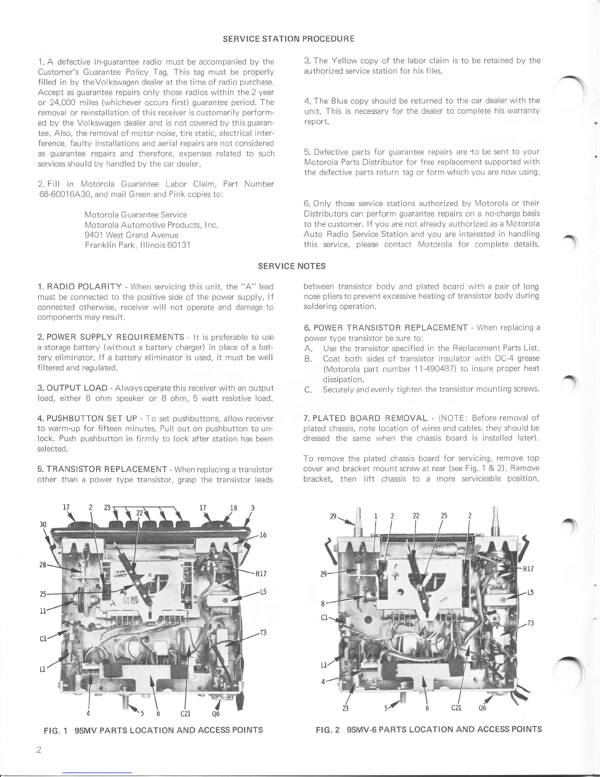
7. PLATED BOARD REMOVAL - (NOTE. Before removal of
plated chassis, note location of wires and cables; they should be
dressed the same when the chassis board is installed later).
To remove the plated chassis board for servicing, remove top
cover and bracket mount screw at rear (see Fiq. 1 & 2). Remove
bracket, then lift chassis to a more serviceable position.
t
-
FIG. 1 9SMV PARTS LOCATION AND ACCESS POINTS FIG.2 9SMV-6 PARTS LOCATION AND ACCESS POINTS

-
35
34
32
FIG.3 gSMV PARTS LOCATION - FRONTVIEW
FIG. 4 9SMV-6 PARTS LOCATION - FRONT VIEW
29
35
34
33
13
n
w
ffi
fi#
&ffi
ffi
:,i!',lil{
.1-,;Jffi
if*fF{ry$|ryry
FIG,5 gSMV TUNER DRIVE ASSEMBLY FIG. 6 9SMV-6 TUNER DRIVE ASSEMBLY

z
o
F
o
o
J
o
F
cc
o-
o
E
o
c0
o
UJ
F
J
L
E
o
o)
6
9
lJ-
+
:!
:_
E=
3= _
iH a
P8 x
o
-'\_.,,*
F9HI' t
I
6
9
F
E
uJ
I
(J
@
E
o
o,
g
lJ-
L
t,
l'l *c
H
T
o
9;
--
@+
a9
at t- - 121 l---lza
=:! lz4 L lz!
:i l- -lgi l. -l3i
a! l--lFJ L:::lFl
A=u
\.t 1// - =
"KeA'-
z
-
x?
6E
sv
@b
g=
Ho
NE
:<
:=
x-
>:,q=
t+p
)0tt IId
{
!
9
z
z
=
!
{
i'cE
5=e
x- = 2 6 q
:d ^- N il I d
;=Ei I !t* = P
o &u I -
is9- .: i= z =?
;! 66 a j e c c
;E=9 ?9 eS =55
-" +1 -'o hq ^ o:
==Fs TT= i;; =:=
E+ !i Hus. E*!E : i =!= == =3T =r=) c Z =
fi- eF 3os -Q== + t F 6=
=s =I E=r 3€E: : r : :=
ii s5 === nE:g E r S ;E
-r3;3
&3 '!! FoeF
Pdrn * {
3= E= i
5- 9e l
9d
-E
Q-
o3
o
-P
=t= s
ii
'9 n;-
tl=lH
;\
;o
=l
:l t:
r - <ff
*ax:
r -E
*3x?
*F
_ _____ ___ ___ ___ _t

(9
z
CE
t!
o=
6o
.^ CC
=n
EE
=o LIJ
=F
fi J
6
L(n
F9'
o
c0 v,
o
E
,
+
F
-

z
o
F
O
o
J
(t) ^
F\
E
o-
o
tr
3t
cnI
ol
IIJ I
FI
J
IL
I
U'
O)
I lr'
fj
-
<^x
dHa
5ne
=?
sg 6 c
E2 ==:
== :sr
o o =N +
i+ s*<
b5 I
da
s\=
f-
H
ls
;\
E,
c
s
o
(J
F
UJ
-I
=dz= \= 8
t 5 X6 e6 (o
=s=ir jr =
5E: == == E
:=EE= E= 9
i5=iq ;s .*
>o : pe2 pdz I
'- ** ==9 E=o .-:
=- , :;- =X-
37 6 Zed Zed
56 ; l*-a 53i
L
nsvE
XT-9HI,
"ll
d
ET
>tz'z rza
:i i= -le: i- -i5:
I -- I tNr
t
3
=l
--
tr/:
,f,(
e;
Y
@=
g_;
€E
@5
E3=
T
^ =AZ
=
;4
ti=c
=
=
tr
z
o
€;
s3
6:
N!
*$
<o
5 E' 6-
- ? >t 6 P
x:- = :E t fr 6
;= r I
;4 ?j - = r,. : L
;: => 5o 96 - 5
;& 9!? o: d= = = :
r* 6a oF z= d i <
}E =o R= 9S E = =
,- t
=; F+ :T= rE;- = : i
E= sI EER' !i=F I r x
[= pf ice ;g!i -* t s
;i +* === =E;= = i I
96 46 +
-= P+ +
F< i6
3'9s !
rf7+-
(( { J--
\!:/-o
J7>-,6
[1r ]--
I=A\+-
I I .i--
u4-.
;s FF
n
=9
-o
^: e
@o * ->
> - L * ai\z
-<+
;=5
E=
g5
o==
I
I
*-o E
E
:=
[-]t'
f,3
=
=
E.E e-[#i",',r] i
==fr -t"^"--< |
ag:E -" r''-ffi=t----------------t
L:-86'.{!,J*th_rf
a:
_€) .-cf;fi[
a


STEP GENERATOR
CONN ECTION
GENERATOR
F R EOU ENCY
(4OO Hertz Mod) TUNER SET TO ADJUST REN/AR KS
Connect an output meter across the
output to maintain 2.83 volts (1
ALIGNMENT
speaker voice coil. Set volume to maximum
watt across B ohm load) on output meter and tone to treble. Attenuate signal generator
at all times to prevent receiver overloading.
^
^'
n
TO CALIBRATE POINTER - Tune radio to 1O0OKhz signal and bend pointer until center of pointer coincides with the center of the
lOOOKhz mark on the dial scale.
HEX
ALIGNMENT
TOOL
BOTTO11/1
CORE
FtG. 13
30 PF
IF ALIGNMENT DETAIL
{\
TOP
c0Rt r_3 L4 t2
RF CORE OSC CORE ANT CORE
1020 KHZ tom KHZ 1020 KHz
\
.O SIGI\AL --,\'
{;l t\Jl RAIOR }-r I
GENERATOR- - }_.uL'\l \A luK --f - I
,no.- | -# | \MtlA.shlriLUAN
L---l---l lllUSl Er AIIACHFL
L ___ l _ _ _.1 uusT Br ATTACHEL
PLUG TO FIT RTCEIVER
ANTFNNA RECEPTACLE
TO RFCI I VER
.>ANTEi\iiA
REC';PTACt.T
'' TO Ptiic
FIG. 14 DUMMY ANTENNA DETAIL
RECEPT 1610 KHZ
FIG. T5 ALIGNMENT LOCATION - gSMV,9SMV-6
1Antenna receptacle
thru 1mf &chassis 262.5Kh2
IF ALIGNMENT
Hiqh end stop T1,r2 Adjust for maximum.
RF ALIGNMENT
2. I Antenna receptacle I '1 610Khz High end stop I CsB, CsA, C1 | ROjust for maximum.
thru dummy (see
Figure)
Note: Do not perform Steps 3, 4, 5 and 6 unless tuner has been tampered with or components have been replaced. Before proceed-
ing with Step 3, back tuning cores as far as possible out of coil forms to eliminate their effect on trimmer adjustments. Remove dial
scale, b:ckground and pilot light socket to expose core screws.
3. I Antenna receptacle 161OKhz High end stop CsB, CsA, C1 | Adjust for maximum.
thru dummy (see
F igu re)
4. 1" 1 020 Khz
1610Khz
Tuner carriage .443"
from high end stop
High end stop
L4, L3, L2 | Adjust for maximum.
5.t" C5B, CbA, C1 | Adjust for maximum.
6. I Repeat Steps 4 and 5 until no further increase; Step 5 should be last step.
7.
FINAL ANTENNA TRIMMER ADJUST
Weak station
around 1400
Khz
MENT
l.' Adjust for maximum
with radio installed in
car and antenna fully
extended.
I2
zND IF
IL 262.5 KHZ
lST IF
262.5 KHZ

MODELS gSMV,9SMV.6 REPLACEMENT PARTS LIST
NOTE: ALL PARTS LISTED ARE RECOMMENDED REPLACEMENT PARTS
/
r
r
REF.
N0. PART
NUMBER DESCRI PTION LIST
PRI CE REF.
N0. PART
NUMBER DESCRI PTI ON LIST
PRICE
23-40302404
64-41668A04
64-4 1668A09
8- 4035380 1
48- 134816
50-4145 1B0 1
50-4126580 1
*50-4345280 1
65-538410
65-122345
500-500- 100
SPARK PLATE
SPARK PLATE
CAPACI TOR.
T: i:Y ll:t:
generator. . . .
TRIMMER, ant: 240-250 PF.
10 MF 6V lytic.
.001 MF 10% 100V my1ar...
.0047 MF 10% 100V my1ar..
TRIMMER, dual: 375-450 PF
45-160 PF. .. .
150 PF 5% 100V N750 disc.
.01 MF 20% 100U my]ar. . . .
.0047 MF 10% 100V my1ar..
160 PF 5% 100V NPO disc..
180 PF 5% 100V N330 d'isc.
.0047 l0% 100V mylar.....
.001 20% 100V Z5F disc...
10 MF 6V lytic.
180 PF 10% 100V ZSF disc.
.005 MF 20% 100U Z5U disc
6V lytic..........
6V lytic..........
10V ]ytic.........
20% 700U Z5U disc
10% 100V N750 disc
ELECTRICAL PARTS.gSMV
CAPACITORS
C1
C2
c3
C4
c5
c6
LO
C9
c10
c11
c1.2
c13
c14
c15
c16
C17
c18
c19
c20
20-407 464t5
23-43280403
8-417 19853
8-417 19809
20-42280801"
2 1-43539A10
8-41,719820
8-417 19 809
*21-43539A46
2 1 -435 39A06
8-417 19809
2t-43538422
23-43280A03
2 1-43538A23
2 i -43538A07
23-43280423
23-43280423
23-43280407
21-43538A09
*20-43539A30
.85 I
1.501
.251
.30 I
50
.15
.20
.30
.25
.15
.30
,20
.55
.15
.15
.25
.30
.15
.15
3.40
.10
.05
on
C2T
c25
c26
E4
E5
.5 MF
.5 MF
.3 MF
.01 MF
10 PF
146
1 .45
1 .45
r.75
1.50
Q1
Q2
Q3
Q4
Q5
Q6
MISCELLANEOUS ELECTRICAL PARTS . gSMV
40
E7,2
E3
L1 | z+-+ozsano+
L2,3 ,4xt-42902813
L5 I ZS-+OtSSeOl
I o-+r+i
I z+-+osoaRos
DIODE, siljcon
sprnrin, 4XBu PM: 8 ;il" "
(esl'4VF)
SPEAKER, 5" PM: 8 ohm
(gSMVG,T,l,l - in some sets).
SPEAKER, 5" PM: B ohm
(gSMVG, T,trll - in some sets)
BULB, dial light (i892)....
FUSE, 5 amp...
TRANSISTORS
258 (RF amp).....
25A (converter). .
248 (IF amp).. .. .
548 (1st audjo)..
54A (driver)... ..
2N176 (power amp)
COI LS & CHOKES
I coIL, antenna. ....... I
lcorls & MTG PLATE.......... I
I cHorr, fjtter. ....... I
I suppRrssoR, choke(9Sl{\lF,G,T)
I suppRrsson, choke(9st4ttt^t).., I
?E
10
.05
.90
.30
1 .05
48- 134805
4B- 134804
4B- 134807
48- 134810
48- 134846
48-134747
R ESISTORS
422ggBO7 I COnrnOl, 20K tone 10K
41995A01 I .Z tOy" PTC t'll,'j. vol
25
25
l5
R17 I 18
R25 Ifl
3-40730A0 1
7 -42251801.
7 -4233780t
7 -42269807
7 -4223580r
*7 -42807801
43-40333803
49-4260780t
76-40553808
76-405538 10
t5-42?04801
15-42276801
45-564457
6r-42179801
44-4079780t
13-42184B01
32-42416407
5-534727
5-5369 18
14- 543810
14-64196A0 1
1-42300841
1-42300B14
1-42300B16
1 -42200B80
36-4223080r
36-4218280r
29-42410401.
29-410 10803
29-41506401
TRANSFORMERS
I z+-+orroerg I rst IF.... ..... I z.rs
I z+-+osrosr + lzna IF.. .. ..... I z.zo
*zs-+zaqosor lourpur. .lt.to
MECHANICAL PARTS.gSMV
BEARING, ball (.093 dja)...1 .05
BEARING, ball (.125 dia)... | .03
BEZEL, incl gasktit(9Sl'lVF,G, I
43-471633
4-4326
13-42236801.
KN0B, incl insert
vol & tunjnS)....'
KNOB, tone control
LUG, adaptor: dual
femal e (di al I 'ight
LUG, trim: female
spkr leads)
LUG, term: female
(fuse receptacle).
T1
T2
T3
1
2
J
6
9
11
lr,w).. ... | 5
13-4217680l lerzel, trim: b1k plastic I
l(gsMvr,,l) ........ I i
84-4288280I leonRo, plated (less comp).. | 1
75
20
05
03
30
20
30
25
40
40
65
10
03
OE
65
B0LT, rcvr mtg:1/4-20X23/32 |
BRACKET, mts (9SI1VF)....... I
BRACKET, mts (9SMVG)....... I
BRACKET, mts (9SMVT). .....' I
BRACKET, Mtg (9SMVI,J) I
BRACKET, plated chassis mtg I
BUSHING, threaded (on tun I
shaft) ......... I
CLUTCH & DISC(incl set I
screw) .... . .. . I
CORE, tuning: ant & RF..... I
C0RE, tuning: osc.......... I
I
COVER, top... ........ I
COVER, trim: blk (gSMVF)... | 5
COUPLING (on tun shaft).... I
CRYSTAL, dial. .......1
CROl.lN GEAR (inc1 gear&disc) |
ESCUTCHE0N, sub.. .... | 1.50
cASKET, spkr mtg (gSMVT-in I
somesets) .....1.15
GROM|\4ET, coil mtg: osc(blk) | .03
GR0MMET, coil mtg: ant & RF I
(red). ......... | .05
INSULATOR, tiansistor...... | .10
I
INSULATOR, gen cap 1ead.... | .15
KIT, installation: comPlete I
(gSMVF)...::.. :........;... | 5.85
KIT, installation: comPlete I
(esMVG) . I 2.i0
KIT, installatjon: comPlete I
(esMVT) ..12.20
KIT, installatjon: comPlete I
(esM\il^l) . I 3.25
13
I4
15
16
t7
18
19
20
2T
( on -off
male - |
to dash) | .10
(dial & I
......... I .05
- male I
| .zo
50
70
10
03
29-42663801.
2-521926
2-r0054425
LUG, term: male (spkr lead)
NUT, hex:radio mtg (9SMVT).
NUT, clip-on:spkr mtg
( esMVG )

REF.
N0. PART
NUMBER DESCRI PT ION L]ST
PRI CE REF.
N0. PART
NUMBER DESCRI PTION LIST
PRI CE
LO
30
)1
JA
22
n)
LJ
24
LO
MECHAN
2-56349t
2-1326t6
2-I3IT7I
l- rJol/ I
2-565333
CAL PARTS - 9SMV (cont)
NUT, hex :1,/ 4-20 rad'i o mtg
(9SMVF, G, W).
NUT, 6-32: spkr mtg (9S|IVT)
NUT, B-32: trim bezel mtg
(9SMVF)
NUT, 3/8-32(trim plate mto)
NUT, hex: 1"/ 4-20 (chassis
ml-n\
.03
.10
.05
.10
.05
L .03
| 2.20
I .20
I .zo
I .rs
I r.ro
I n,
I
| 'uo
| 'ou
| .03
.05
.15
.03
.03
.03
.05
.05
.03
.03
.03
.05
r.20
.15
.30
,t
I .zo
I .15
.10
.10
.05
33.65
c1
C2
t.J
C4
a(
C6
to
C9
c10
c11
C12
c13
c1"4
c15
ci6
C17
c18
c19
C2I
c25
c26
Et,2
E3
E4
L1
L2,3
L5
34
35
Q1
Q2
Q3
Q4
Q5
Q6
R17
R25
R26
R28
R29
4-40246A1.0
4-4242240I
4- 40 10440 7
ELECTI
20-407 464t5
23-43280A03
8- 417 19853
B-41719820
20-4228080r
2 1- 43539410
B-4171.9820
8-4 17 19809
2r-43539446
k2 1-43539A48
B-417 19805
2l-43538422
23-43280403
21-43538A23
2 1-43538A09
23-43280423
23-43280423
23-43280402
21-43538A09
23-40302404
64-41668404
64-41668409
B-4035380 1
YIISCELLANEOUI
48- 134816
50-41265B01 l
I
50-43452B01 |
I
65- i25595
(
24-407BBAO4 I
+ r-42so2B:.3 I
x25-40755812 I
48-13480s I
48-134804 I
48-134807 I
48-134811 |
48-134810 I
I
48-134747 I
*18- 42808802
*6- i0053c09
*1 7-41995406
*6- 10053D90
17-41995A01
WASHER, "C" (tuning shaft).
WASHER, flat (tuning shaft)
WASHER, spring (tuning
shaft)
IICAL PARTS - 9SMV-6
CAPACITORS
TRIMMER, ant: 240-250 PF...
i0 l'4F 6V lytic.
.001 MF 10% 100V my1ar.....
.01 l4F 20% 1"00\'l my1ar......
TRII4MER, dual: 375-450 PF
45-160 PF....
150 PF 5% 100V N750 disc...
.01 MF 20% 1.00U mylar......
.0047 MF 10% 100V mylar....
160 PF 5% 100V NPO disc....
220 PF 5% 100V N470 disc...
.0022 MF 10% 100V mylar....
.001 20% 100V Z5F disc.....
10 MF 6V lytic.
180 PF 10% 100V Z5F disc...
.01 l'4F 20% l00U Z5U disc...
.5 MF 6V 1ytic.
.5 MF 6V lytic.
2 MF 10V lytic.
.01 MF 20% I00V Z5U disc...
500-500-100 MF 16V 1ytic...
SPARK PLATE
SPARK PLATE
CAPACITOR, generator.
S ELECTRICAL PARTS - 9SMV.6
DI0DE, siljcon
SPEAKER, 5" PM: 8 ohm VC
(in some sets).
SPEAKER, 5" Pl4: 8 ohm VC
(in some sets).
BULB, dial light (1847)....
)OILS & CHOKES
C0IL, antenna....
COILS & MTG PLATE
CHOKE, fi l ter.
TRANSISTORS
258 ( RF amp) . .
25A (converter)..
248 (IF amp)..
54D (lst audjo)
54C (driver).....
2N176 (power amp)
R ESI STO RS
CONTROL,20K tone 10K vol..
100 5% t/zw..
43 5% l,JW.
r50 5% 1t,J....
.2 1.0% PTC Wt^l.
03
10
OE
EF
25
20
10
AE
80
50
15
IU
30
25
25
20
q6
15
15
55
55
60
15
55
1
6
3
40
60
30
05
1.45
1 .45
1 .45
r.20
t.75
3.55
12
EN
.20
2-1.21.771 3/8-32(dual controlNUT,
min )
64-42267807
52-40244826
38-42 18580 1
9 -53 1066
9-42401.801.
42-7021941.0
PLATE, spkr mtg (9SMVT in
some sets).....
POINTER & ARM.
PUSHBUTTON
RECEPTACLE, antenna
RECEPTACLE, fuse
RETAINER, "E" ring (pointer
mfn\
34-42 180B03
3-13?352
3- 136368
3-134144
1- 562830
?_ ?aEa
3- 135 139
3-13?220
3 - 56069 5
3-1247rr
3-135531
3-r25452
3- 13 1367
3- 136 120
3-4207 4801"
1-40391B02
26 - 40396 B0 1
9-42576414
9-43089A01
4t-42234801
41-40648801
4 1 -41805A0 1
46-565260
29-64295401
SCALE, dial..
SCREW, mach j ne: B-32XI/ 2
(trim bezei mtg - 9Sl1VF)...
SCREW, machi ne :6-32X5/ B
(spkr to mtg plate - gSllVT)
SCREW, machine: 1/ 4-20XI/2
(support brkt mts - gSllVG).
SCRTW & NUT, adj
SCREW, set:4-40X1/4
& disc)
SCREI^J, tpg:8-18X1/4
mtg) . .
( cl utch
i;;;;;'
SCREl^l, tpg:4-40X5/16 (tuner
coi I mtg)
SCREW, soecjal :6-20X5/32
(transistor mtg)..
SCREW, tpg 6-32XI/2 (tuner
mtg Phillips head)
SCREW, tpg:B-15X1/2 (spkr
mtg - gSllVF). ....
SCREW, tpg:8-15X1/2 (spkr
mtg - 9SI4VG).....
SCREW, tpg:8-32X5/16 (radio
to mtg brkt).
SCREW, tpg:10-12X1 /2 (radio
brkt mtg - gSllVF)
SCREW, tpg:1.2-I2Xl/2 (spkr
mtg - gSllVW).. ...
SHAFT, manual tun (incl
cl evi s coupl i ng)
SHIELD, 1 ight.
SOCKET, pi l ot l i ght&l ead. . .
SOCKET, transjstor..
SPRING, clip (chassis mtg).
SPRING, cl utch re1 ( tuner) .
SPRING, pointer tension....
STUD, trimount (dia1 crys-
tal mtg)
TERMINAL, qui ck-sp1 i ce (gen
77 -42901801 TUNER, AT-708: complete
-\
a\
-$

-
r
REF.
N0. PART
NUMBER DESCRI PT ION LIST
PRI CE REF.
N0. PART
NUMBER DESCRI PTI ON LIST
PRICE
T1
T2
T3
MI
1
?
4
5
6
7
o
()
10
1.2
1)
AJ
r4
16
21
19
20
SCELLANEOUS T
*40-43221"80r I
l
24-40310B13 I
24-40370814 I
x25-40755874 I
MECHA
43-477633 I
43-4326 I
*64-43231801 I
84-42BB2BO7 I
3-40730AO1 I
I
7-42BO7B\1 I
*7-43223807 I
k43-43224801 I
k43-42s7OB03 |
47-40801805 I
45-564457 I
15-42204801, I
67-4217sBOr I
13-42184801 t
32-4222s802 I
32-42416A01 I
I
5-536918 I
5-534727 I
I 4-641 96A01 I
14-543810 I
*1-43000877 I
36-4003e801 I
36-42423801 I
29-40410A01 I
I
29-41010803 I
I
29-41506A01 I
I
2s-42663801 I
2-565333 I
2-721777 I
2-5634s7 I
2-132676 I
LECTRICAL PARTS - 9SMV-6 (co
SWITCHES
SWITCH, slide 6V - 12V.....
RANSFORMERS
1st IF.
2nd IF.
OUTPUT.
NICAL PARTS - 9SMV.6
BEARING, ball (.093 dia)...
BEARING, ball (.125 dia)...
BEZEL, trim..
B0ARD, plated (1ess comp)..
BOLT, speci a1;I/ 4-20 rcvr
mtg. . .
BRACKET, plated chassis mtg
BRACKET, switch
BUSHING & CROWN GEAR. ......
BUSHING, tuning shaft......
CLUTCH SHAFT & PINION GEAR
C0UPLING (on tuning shaft).
COVER, top. . .
CRYSTAL, dial sca1e........
ESCUTCHE0N, sub.
GASKET, trim bezel.
GASKET, speaker.
GRO|"IMET, red (mtg plate)...
GROMI'4ET, bl k (mtg pl ate) . . .
INSULATOR, generator cap...
INSULATOR, transistor.. . . ..
KIT, insta1Iation: complete
KNOB, tone.
KN0B, vol une. . .
LUG, adaptor:dual nale-fe-
male (dia1 liqht to dash)..
LUG, term: female (dia1 &
speaker 1 eads )
LUG, term: female-ma1e(fuse
receptacl e)
LUG, term: male (spkr lead)
NUT, 1/4-20 (chassis mtS)..
NUT, 3/8-32 (control mtq)..
NUT, 1/4-20 ( radi o mtg-Gh i a
NUT, 6-32 (spkr to dash)...
2.r5
2.20
on
t)
.05
.03
1..25
1 .05
.03
.15
1E
. tJ
.30
.03
2.00
1 .50
.30
.15
35
50
10
05
05
03
1tr
10
20
10
05
03
03
10
22
LJ
24
25
t1
29
30
31
34
35
2-I0054425
2-179973
52-40244826
9-531066
9-42401.80r
42-1.021.9410
,34-42180804
3-1.28262
3- 136368
3-134144
3- 563 128
3 - 560695
) 1)OnaA
3-135i39
3-42074801
3-r25452
3-1247tr
* 1 -4039 1B06
*9-42576415
9-43089A0 1
43-43527 406
47-42234802
4 1 -4 1805A0 1
42-56537 4
46-565260
29-64295407
77 -4290t807
4- 1 36385
4- 50 1 364
4-4242240r
4-40 104A07
NUT, cl'ip-on (spkr mtg-Ghia
NUf, 8-32 (spkr mtg-transp)
POINTER & ARM.
RECEPTACLE, antenna
RECEPTACLE, fuse.
RETAINER, "E" ring(pointer
mfn\
03
05
03
10
03
05
03
05
05
05
05
10
05
.05
.05
.20
.15
1. 10
03
60
05
30
25
30
20
10
l5
i5
aaAl tr niel
SCREW, machine: B-32X1"
(spkr mtg - transport). .. ..
SCREW, machine: 6-32X5/B
(spkr to dash - transport) "
SCREW, machjne: I/4-20X1/2
(support brkt mtg-Ghja)....
SCREW, set: 4-40X.31(clutch
rlicn\
SCREW, special : 6-20N,5/32
(transistor mtg)..
SCREI^J, tpg: 4-40X5/16(coil
& housing mtg)
SCREW, tpg: 8-18X1/4 (cover
mtq), .
SCREW, tpg: I2-72X1l2 (spkr
mts) . .
SCREI,J, tpg: 8-15X1/2 (spkr
mtg-Ghia)
SCREW, tpg: 6-32X1l4 (tuner
mts) . .
SHAFT, manual tuning: com-
pl ete ( i ncl cl evi s coupl i ng
S0CKET, pilot 1ight..
SOCKET, transistor..
SPACER, control mtg........
SPRING, c1 ip (chassis mtg).
SPRING, pointer tension....
STRAP, rece'i ver mtg........
STUD, trimount (dial scale
mtg) . .
TERI4INAL, female :qui ck
splice (generator cap).....
TUNER, MTS-721: comp1ete...
WASHER, flat (control mto).
WASHER, "C" (manual tuning
shaft)
l^lASHER, flat (manual tuning
sh aft)
WASHER, spring (manual tun-
ing shaft)
PRICES AND SPECIFICATIONS ARE SUBJECT TO
* DENOTES NEW ITEM APPEARING IN ANY CHANGE WITHOUT NOTICE
LIST FOR FIRSTTIIVIE
This manual suits for next models
1
Popular Car Stereo System manuals by other brands

Fiat
Fiat AD 182 M Service manual

JL Audio
JL Audio Stealthbox SB-D-MAG/10W3v3 installation guide

Clarion
Clarion BKX-1321-03 installation manual

Premier
Premier SCR-4637USID instruction manual

Sony
Sony CDX-454RF - Compact Disc Changer System Installation/connections

Sony
Sony DSX-GS900 operating instructions