MP3 Solid Air WK25 Series User manual

Brandkleppen manual
P stbus 22756
1100 DG Amsterdam Z.O.
Tel.: +31 (0)20 696 69 95 Fax: +31 (0) 20 691 30 62
mail@s lid-air.nl www.s lid-air.nl
Solid Air
®
Solid Air®Luchtverdeeltechniek BV Telefoon (020) 696 69 95 Fax (020) 691 30 62 www.solid-air.nl Brandkleppen manual 06 2013
Brandkleppen manual
WH25
WH45
WK25
WK45
1
1MLWK
25R0G
Via G. La Pira, 9 A-B
Camposampiero
3 5 0 1 2 P D - I t a l y
www.mp3-italia.it
MAINTENANCE AND USE MANUAL
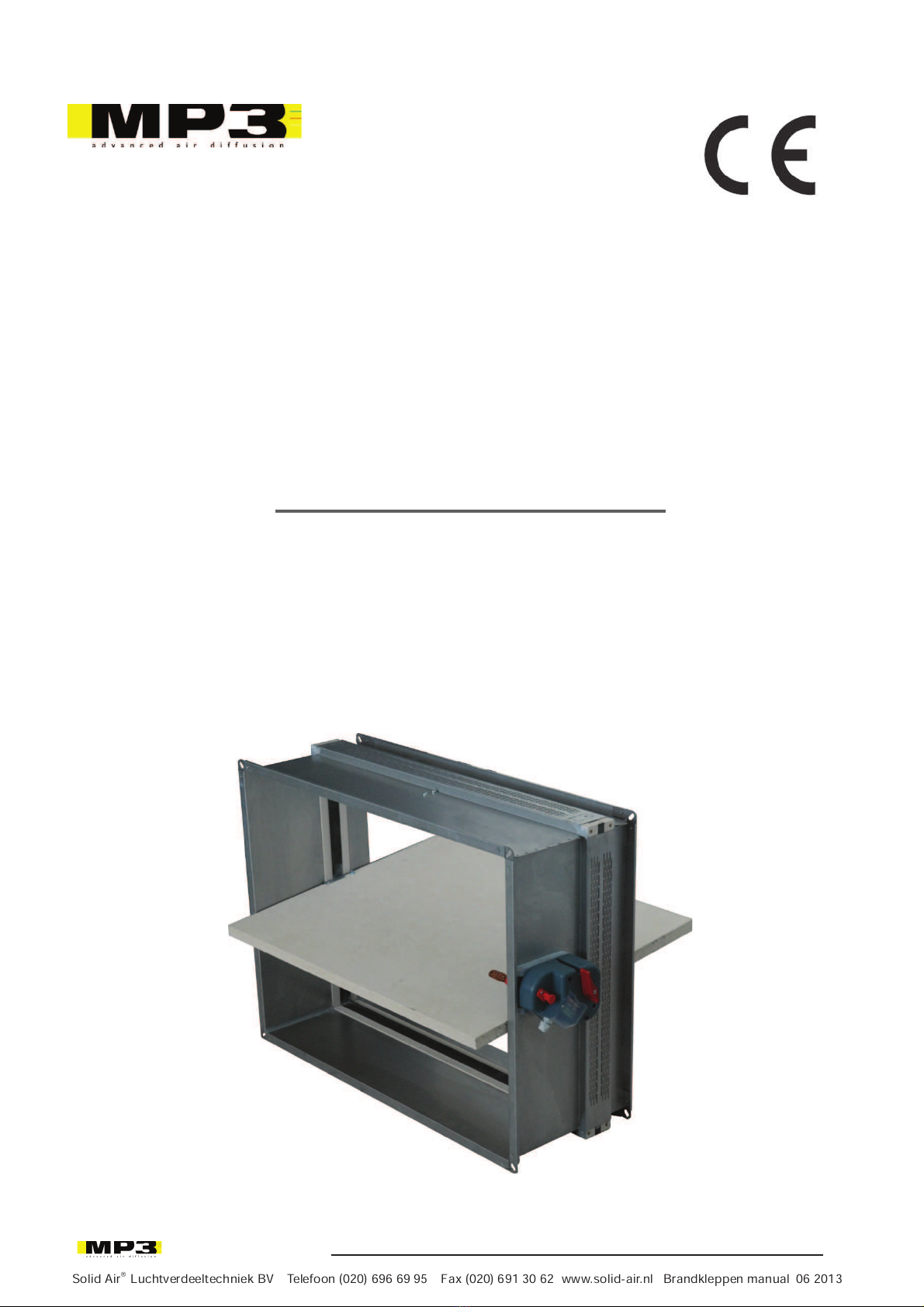
WK25
Rectangular fire damper with low pressure drop
500 Pa
Solid Air®Luchtverdeeltechniek BV Telefoon (020) 696 69 95 Fax (020) 691 30 62 www.solid-air.nl Brandkleppen manual 06 2013
Solid Air®Luchtverdeeltechniek BV Telefoon (020) 696 69 95 Fax (020) 691 30 62 www.solid-air.nl 06 2013
Brandkleppen manual
WH25
WH45
WK25
WK45

2
1MLWK
25R0G
1. PRODUCT PRESENTATION
The WK25 rectangular fire dampers are installed in ventilation ducts inside walls to stop a fire from spreading.
They have a modular mechanism, entirely outside the walls.
The duct is built in galvanised steel.
The fire damper can be fitted with a simple thermal fuse, or a remote controlled automatic mechanism.
•
Tested in compliance with
EN 1366-2 to 500 Pa.
• Control mechanism entirely outside wall.
•
Easy to install.
•
Maintenance free.
2. RANGE OF DIMENSIONS
Free area (dm²) = [(width – 12) x (height – 37)] / 10 000
with width and height in mm
4
3
2
5
6
1
7
1. Galvanised steel duct.
2. Moveable blade in refractive material.
3. Control mechanism.
4. Connection flanges.
5. I
ntumescent seal.
6. B
lade seal.
7. Thermal fuse.
Solid Air®Luchtverdeeltechniek BV Telefoon (020) 696 69 95 Fax (020) 691 30 62 www.solid-air.nl Brandkleppen manual 06 2013
Solid Air®Luchtverdeeltechniek BV Telefoon (020) 696 69 95 Fax (020) 691 30 62 www.solid-air.nl 06 2013
Brandkleppen manual
WH25
WH45
WK25
WK45
Solid Air®Luchtverdeeltechniek BV Telefoon (020) 696 69 95 Fax (020) 691 30 62 www.solid-air.nl Brandkleppen manual 06 2013
Solid Air®
3
1MLWK
25R0G
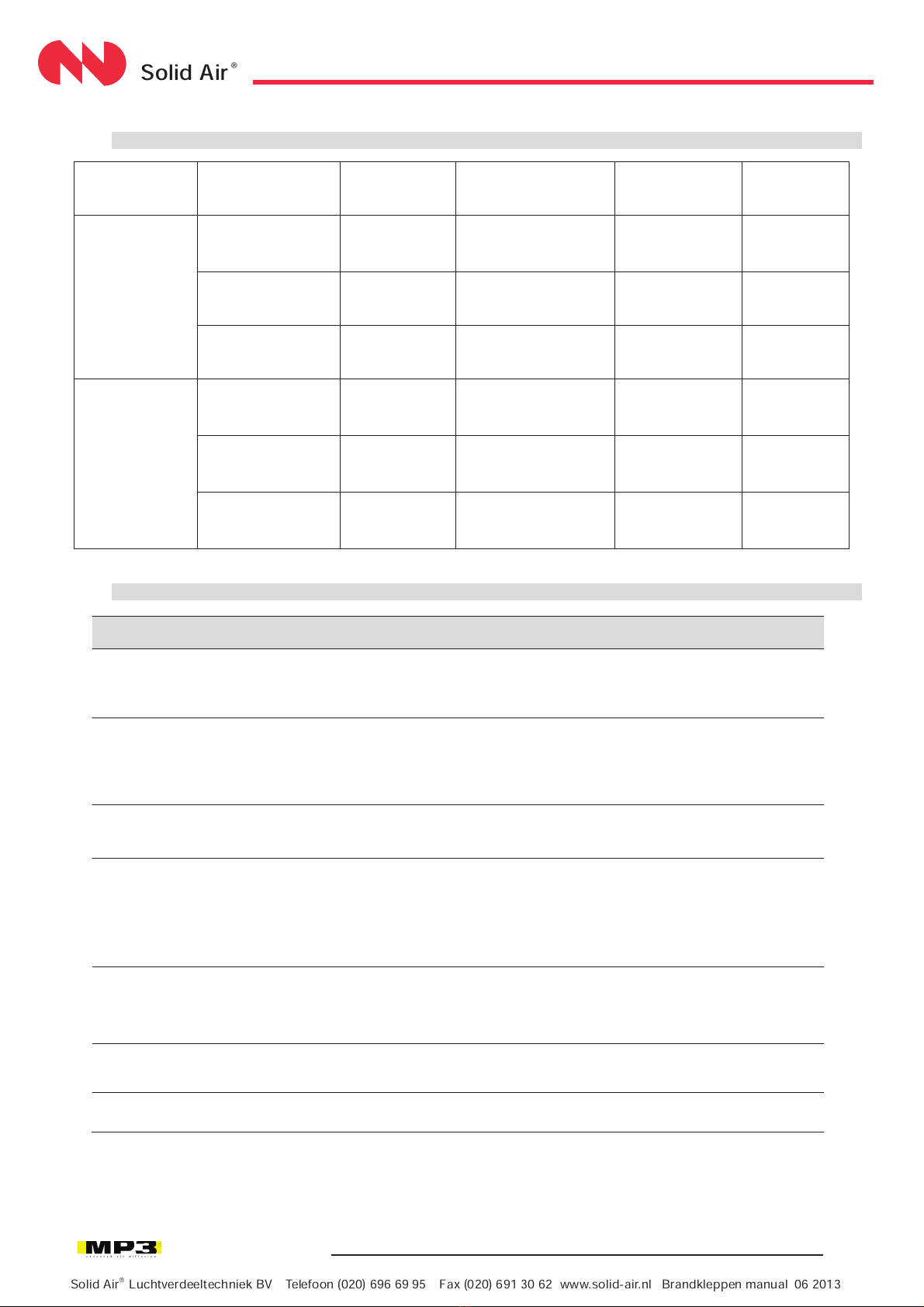
3.
FIRE RESISTANCE IN COMPLIANCE WITH EN 13501-3: 2005 (500 Pa)
INSTALLATION
MATERIAL
CLASSIFICATION
MECHANICAL
ORIENTATION
DIMENSIONS
FIRE
DIRECTION
WALL
(Flush mounted
in wall)
Aerated concrete
Thickness 100 mm
Density 550 kg/m
3
EI 120 S
Horizontal or vertical
blade axis
100X200 to
800X600
Indifferent
Plasterboard type
98/48
EI 60 S
Horizontal or vertical
blade axis
100X200 to
800X600
Indifferent
Carreaux de platre
Gypsum blocks
Thickness 70 mm
EI 90 S
Horizontal or vertical
blade axis
100X200 to
800X600
Indifferent
FLOOR
(Flush-mounted
with floor)
Reinforced concrete
Thickness 150 mm
Density 2200 kg/m
3
EI 180 S
Horizontal blade axis
100X200 to
800X600
Indifferent
Aerated concrete
Thickness 150 mm
Density 650 kg/m
3
EI 120 S Horizontal blade axis 100X200 to
800X600 Indifferent
Aerated concrete
Thickness 100 mm
Density 650 kg/m
3
EI 90 S
Horizontal blade axis
100X200 to
800X600
Indifferent
4. DETAILED TECHNICAL DATA
CONTROL
MECHANISM
WK25B
WK25M
WK25 V/D
Product type
Automatically controlled
fire damper.
Rectangular cross section.
Automatically and remote
controlled fire damper.
Rectangular cross section.
Automatically and remote
controlled fire damper.
Rectangular cross section.
Mandatory
Manual reset by direct
action on the moveable part
after closing when cold.
Manual reset by direct action
on the moveable part after closing
when cold.
Safety position contact (limit switch)
DCU/FCU (S2).
Motorized reset after
closing
when cold
(can be local or
remote).
Safety position contact (limit
switch).
Safety options
Safety and standby
position contacts (S2).
Operating mode
Without external energy.
Without external energy for
power supply input magnet
during stand-by.
With external energy for power
supply interruption magnet
during stand-by.
With external energy.
Control mode
Automatic:
by fuse at
70°C±7°C.
Automatic: by fuse at 70°C ± 7°C.
Remote control: by power supply
input or interruption on the magnet.
Automatic: by fuse at 72°C ± 7°C.
Remote control: by
power supply
interruption.
Installing position
Horizontal or vertical blade
axis.
Horizontal or vertical blade axis.
Horizontal or vertical blade axis
Air circulation
direction
Indifferent.
Indifferent.
Indifferent.
Solid Air®Luchtverdeeltechniek BV Telefoon (020) 696 69 95 Fax (020) 691 30 62 www.solid-air.nl Brandkleppen manual 06 2013
Solid Air®Luchtverdeeltechniek BV Telefoon (020) 696 69 95 Fax (020) 691 30 62 www.solid-air.nl 06 2013
Brandkleppen manual
WH25
WH45
WK25
WK45
Solid Air®Luchtverdeeltechniek BV Telefoon (020) 696 69 95 Fax (020) 691 30 62 www.solid-air.nl Brandkleppen manual 06 2013
Solid Air®
4
1MLWK
25R0G
Certificates:
5. HANDLING AND STORAGE
Since this is safety equipment, the fire damper needs to be stored, handled and installed with care.
Attention:
• Avoid contact with water and exposure to excessive dampness.
• Avoid damage to sealing/gasket during installation. Be careful especially to the external sealing/gasket.
• Avoid deforming the duct during assembly and sealing.
It is best to:
• Unload in a dry area.
• Avoid impacts.
• Do not use the damper as a work table or scaffolding.
• Do not put small dampers into bigger ones.
6. INSTALLATION AND COMMISSIONING
• Installation is possible with the blade axis in horizontal or vertical position.
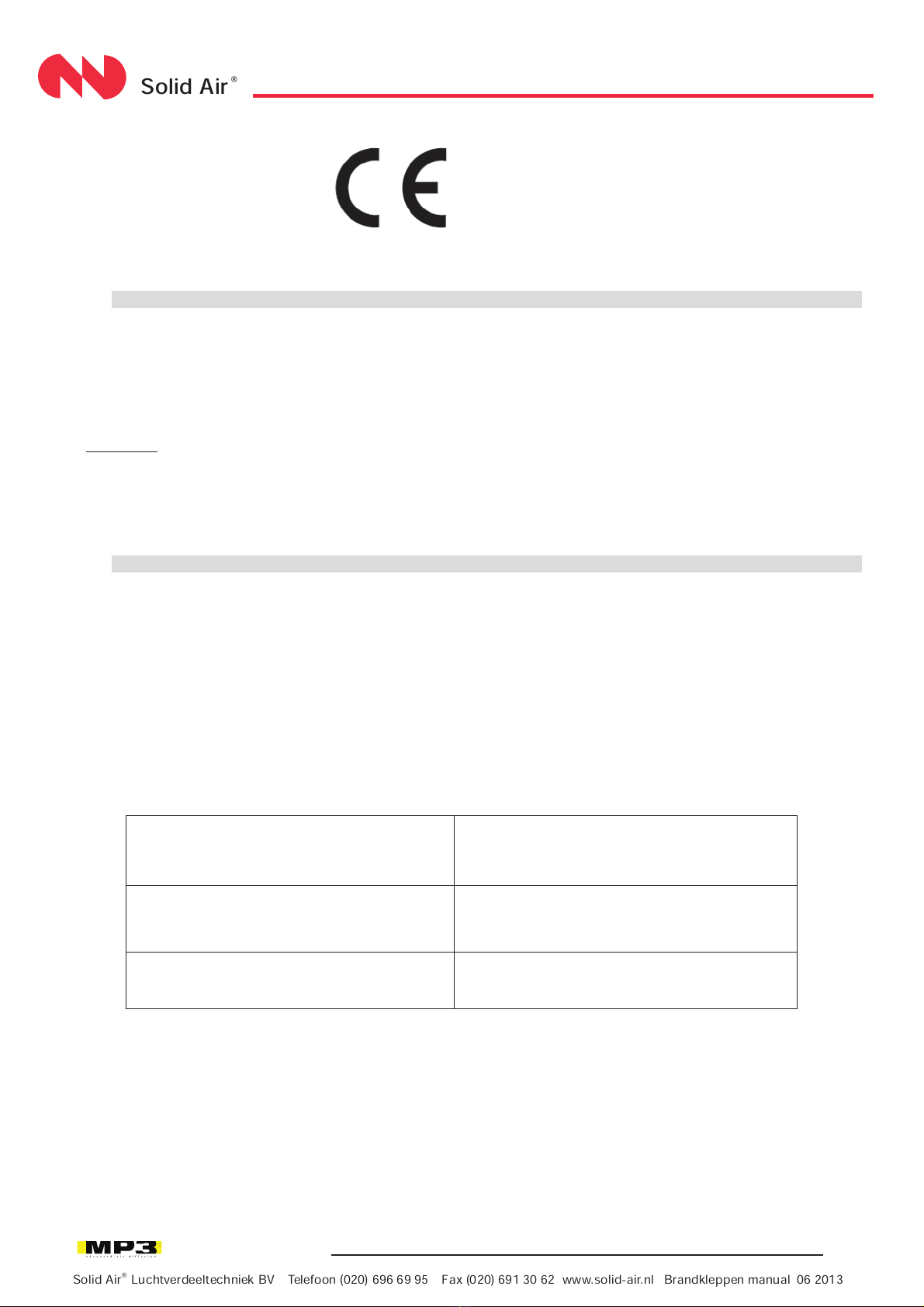
• The installation must comply with the CE Certificate.
• Never obstruct the blade movement with any object or air ducts.
• The air tightness and fire resistance class is maintained if the damper installation is done in compliance with the
technical specifications.
• Use temperature: 50°C maximum.
The WK25 fire damper is always tested in the frame of standardised supports in compliance with EN 1366-2 : 1999
table 3/4/5'. The results obtained are valid for all similar support frames which have a thickness, density and fire
resistance equal or higher than that of the test.
Example of similar constructions:
aerated concrete wall thickness 100 mm +
density 550 kg/m3 + fire resistance up to 120
minutes
brick walls, reinforced concrete, aerated
concrete wall, etc.+ fire resistance minimum 120
minutes
aerated concrete floor thickness 100 mm +
density 650 kg/m3 + fire resistance up to 90
minutes
parts in concrete, prestressed concrete, etc.
+ fire resistance minimum 90 minutes
flexible wall – metallic uprights +
plasterboard: 100 mm + fire resistance 60
minutes
metallic uprights + plasterboard
+ fire resistance minimum 60 minutes
Solid Air®Luchtverdeeltechniek BV Telefoon (020) 696 69 95 Fax (020) 691 30 62 www.solid-air.nl Brandkleppen manual 06 2013
Solid Air®
Solid Air®Luchtverdeeltechniek BV Telefoon (020) 696 69 95 Fax (020) 691 30 62 www.solid-air.nl Brandkleppen manual 06 2013
Solid Air®Luchtverdeeltechniek BV Telefoon (020) 696 69 95 Fax (020) 691 30 62 www.solid-air.nl 06 2013
Brandkleppen manual
WH25
WH45
WK25
WK45
This manual suits for next models
4
Table of contents
Popular Fan manuals by other brands


Harbor Breeze
Harbor Breeze RLG52NWZ5L manual

Allen + Roth
Allen + Roth L1405 instruction manual

ViM
ViM KUBAIR F400 ECOWATT Technical manual

HIDRIA
HIDRIA R10R-56LPS-ES50B-04C10 user guide

BLAUBERG Ventilatoren
BLAUBERG Ventilatoren CENTRO-M 100 L user manual

Triangle Engineering
Triangle Engineering HEAT BUSTER SPL Series owner's manual