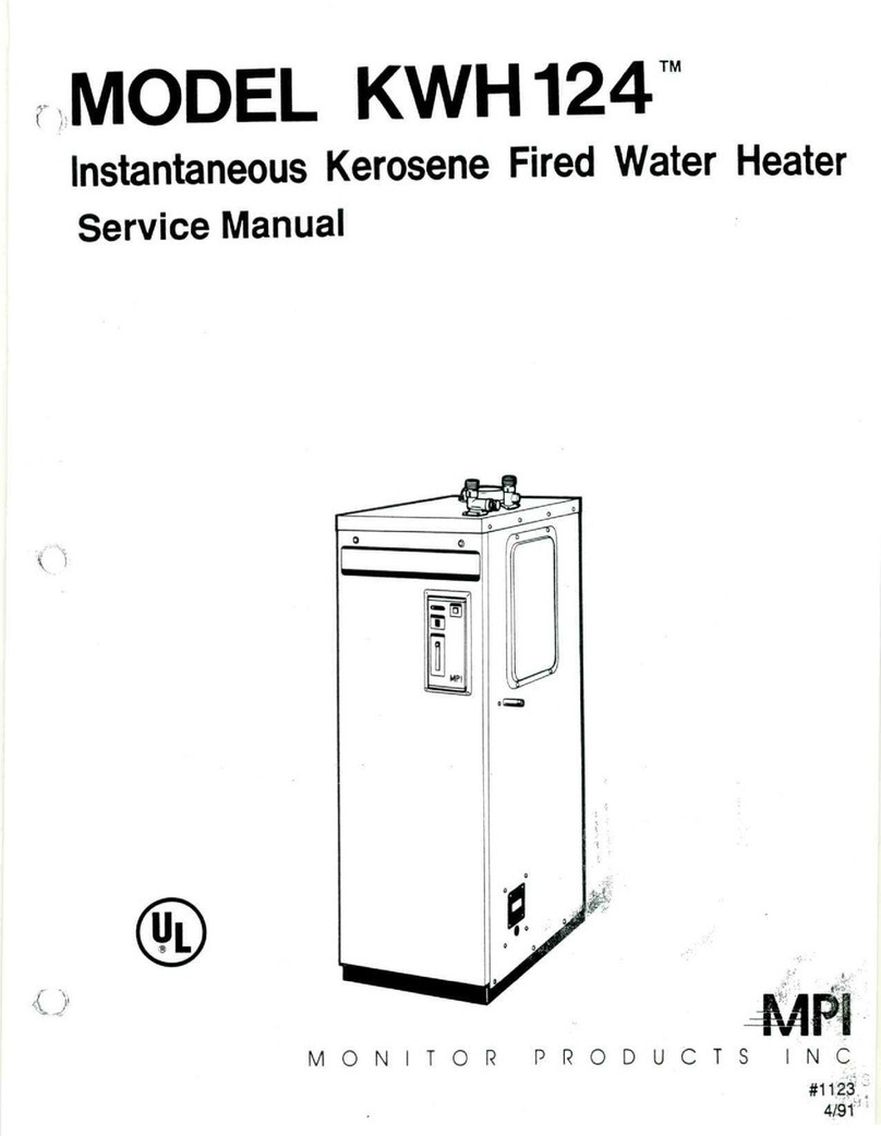
MPI KWH124 User manual

MODEL
KWH124™
Instantaneous
Kerosene
Fired
Water
Heater
Owner's
Manual
Thank
youfor
choosing
the
KWH124
InstantaneousKerosene
Fired
WaterHeater.
We
are
sure
that
the
moderndesign
and
outstanding
performance
of
thisunitwill
meetyour
highest
expectations.Pleaseread
this
manual
and
warningscarefully
before
usingyour
KWH124
KeroseneFiredWaterHeater.Pleasebecome
fully
acquainted
with
all
details
ofits
operation
so
that
youcanusethe
KWH124
for
many
years
without
problems
or
malfunctions.Keep
this
manualhandy
for
reference.
4AP\
MONITOR
PRODUCTS
INC

INDEX
1.
SPECIALPRECAUTIONS
2.
SPECIFICATIONS
2
A.
PARTSDESCRIPTION
2
•
APPEARANCE
2
•
CONTROLPANEL
2
•
CONSTRUCTION
2
B.
SPECIFICATIONS
3
C.
DIMENSIONALOUTLINEDRAWING
4
3.
OPERATIONAL
PROCEDURES
5
A.
FUELTYPE
'5
B.
FUEL
SUPPLY
5
C.
PRE-OPERATION
CHECKLIST
• 6
D.
START
UPAND
OPERATION
•
6
E.
UNIT
SHUT
OFF
•
8
F.
FREEZEPREVENTION
• 8
G.
WARNINGS
9
4.
SAFETYDEVICES
10
5.
MAINTENANCECHECKLIST
•
11
6.
REGULARCLEANING
12
7.
TROUBLESHOOTINGGUIDE
13
8.
SCHEMATICDISASSEMBLY
16
The
KWH124
is
designed
for
household
useforthe
purpose
of
supplying
hot
water.
The
unit
should
notbe
used
ona
moving
vehicle
such
asa
boat
or
camper.
Warrantycoverage
for
commercialapplication
could
be
voided
or
limited
to1
year.

1.
SPECIAL
PRECAUTIONS
WARNING
Use
onlycrystalclear
1-K
kerosene.Never
use
gasoline,
white
gas,campfuel
or
other
flammable
liquids.
Useof
suchfuels
can
result
inan
explosion
and
causesevere
injury.
A
damaged
or
malfunctioningpartshould
be
discarded
andbe
replaced
with
a new
genuine
service
part.
All
repairs
should
be
left
to
professionals.
Contact
your
local
authorized
service
dealer.
CAUTION
DO
NOT
STOREflammableliquids
or
materialssuch
as
gasolinenear
the
unit.
Makesure
that
the
flue
is
properly
installed
and
connected.
A
separation
inthe
flue
during
the
operation
ofthe
unit
can
cause
the
release
of
exhaust
gas
into
the
room.
The
consequencescould
be
dangerous.
Turn
off
unit
in
case
ofan
accident
oran
emergency.Stay
calm
anddonot
panic.
Just
turn
offthe
unit.
In
case
ofa
fuel
leak,
exhaust
fumes
in
home,
nohot
water.
Turn
off
unit.
Call
an
authorized
serviceperson.
When
using
a
shower,feel
the
temperature
ofhot
water
with
your
hand
first,
before
movingyourselfunder
thehot
water.
Avoid
theuseof
hardwater.
In
regionswherehard
water
isthe
onlysource,take
advantage
ofa
watersoftener.
This
unit
is
only
for
indoor
use.Avoid
its
exposure
to
rain
or
moisture.

(2.
SPECIFICATIONS")
A.
PARTSDESCRIPTION
•
APPEARANCE
Hot
Water
Outlet
Drain
CONTROL
PANEL
CONSTRUCTION
Coid
WaterIntake
Fan
Motor
Printedcircuit
Board
Hot
Water
Thermistor
ColdWater
Intake
-Filter
-
Control
Panel
Front
Door
Maintenance
Cover
FuelFilter
Connection
Junction
Box
Run
Lamp_______^
Code
LED
Temperature
. —
Adjusting
Knob
Oi
•s
mm
MM
|
LCW
SS3
zsm
1
Eza
UC-J.
asssf
D-
ON<fF
MPI
Power
Lamp
-
Power
Switch
Hot
Water
Outlet
Air
Damper
Mixing
Tank
Burner
Overheat
ProtectorThermo
HeatExchanger
TemperatureFuse
-2-

B.
SPECIFICATIONS
Model
KWH124
Type
CombustionType
Air
Intake/Exhaust
Heating
Source
of
Water
Ignition
Fuel
Hot
Water
OUTPUT
FuelConsumption(Max)
Efficiency
Capacity
of
HeatExchanger
MaximumPressureApplied
Minimum
WaterFlow
to
ActivateBurner
Area
of
HeatTransmission
Exterior
Dimensions
Weight
Voltage/Frequency
Rated:
Ampere
(RatedPowerConsumption)
FlueSize(Diameter)
Exhaust
Air
Temperature
PressureVapor
Indoor/Forced
Exhaust
Instantaneous
DirectConnection
to
mainsupply.
HighVoltageDischargeSpark
CrystalClean
1-K
Kerosene
123.000
BTU/H
1.1
GAL/H
86%
X
1.057
OT
(1.0
L)
150PSI
0.45
GAL/MIN
620
in2
35
in(H)
x
11.8in(W)
X
20.9in(D)
88
Ibs
AC
120V/60Hz
Ignition:
1.05A(127W)
Combustion:
1.00A
(HOW)
4
in
482T
Nozzle
Quantity
of
Vapor
Spray
Pattern
Spraying
Angle
TemperatureFuse
Electric
CurrentFuse
SafetyDevices
0.85GPH
Pattern
A
60°
302T
6
A
*Safe
Ignition
*
FlameSensor
*Over
Heat
Protector
*Air
Pressure
Switch
*
SurgeAbsorber
PipeConnection
Water
Intake
Hot
Water
Outlet
Drain
Accessories
(supplied)
Hot
Water
Outlet
(Maximum)
Degree
Rise
3/4NPT
Male
3/4NPT
Male
1/2NPT
Male
Fuel
Filter
Water
Intake
Insulator
Hot
Water
Outlet
Insulator
70F
Rise
210
GAL/H
3.5
GAL/MIN
80F184
3.07
90F
164
2.73
100F
147
2.45
11
OF134
2.23
(Maximum
hot
watersupplied
by
this
unit
is
about
221
GAL/H.)
>KThis
represents
Efficiency
under
laboratory
conditions.
This
efficiency
rating
can
vary
upto4%.
"SINCE
WEARE
CONSTANTLY
IMPROVING
OUR
PRODUCTS,
ALL
SPECIFICATIONS
ARE
SUBJECT
TO
CHANGE
WITHOUT
NOTICE."
-3-

C.
DIMENSIONALOUTLINEDRAWING
(Unit-.Inches)
6.1
3.1
3.1
Hot
Water
Outlet
VentConnector
Cold
Water
Intake
10.6
10.2
Drain
Fuel
FilterConnection
\
1.7
£
'
00
(
I
EEC
11.8
-4-

3.
OPERATIONAL
PROCEDURES)
A.
FUELTYPE:
Use
only
crystal
clear
Type
1-K
Kerosene.
B.
FUEL
SUPPLY
—
Precaution
-
No
water
or
debrisshould
be
allowed
to
enter
the
fuel
tank.
Whenthese
two
are
mixed
with
fuel,imperfectcombustion
can
resulttherebyshortening
the
life
of
the
burner.
1.
Keep
the
tankfilter
cap
tight.
2.
Donot
allow
tank
torun
empty.
If
the
KWH124
is
allowed
to
operate
without
fuel,
air
must
be
purged
inthe
following
manner:
a.
Refill
kerosene
tank.
b.
Allow
30
minutesafterrefilling
to
activate
KWH124.
(This
allowsfuel
to
settle.)
Fuel
purge
screw
c.
Makesuretankvent
is
open.
d.
Open
shut-off
valve
on
fuel
tank.
Loosen
air
purgescrew
at
fuelfilter.
Discharge
airoutofall
channels
through
whichfuelruns.
e.
Fill
the
bowl
ofthe
unit
fuel
filter
with
kerosene.
Fasten
fuelpurgescrewback
in
originalposition.
Handle
O
—Ring
of
fuelpurge
screw
carefully.
A
damaged
0
—Ring
can
cause
fuelleakage
and
render
unit
inoperative.Don'tmisplace
0
—Ring.
f.
Wipe
all
fuelspills
off
thoroughly.
-5-

C.
PRE-OPERATION
CHECKLIST
1.
Water
Leaks
Open
the
valve
andrun
waterthrough
unit
tosee
that
waterrunsproperly
through
heat
exchanger.
No
watershould
be
leakingfrom
it,orany
fittings.
2.
Fuel
Leaks
Make
sure
that
there
isno
fuelleakingfromfueltank,filters,
valves
or
from
anyofthe
piping
connections.
3.
Location
Makesureproperclearances
are
kept
around
unit
and
there
is
nothing
flammablenearby.
Keep
a
distance
from
walls
of
combustiblematerial.
From
left
side
7 in
(180
mm)
From
right
side
19in
(505
mm)
Fromback
of
heater
8 in
(205
mm)
From
Heater
to
closetdoor
29in
(735
mm)
Flue
pipe
to
combustiblesurface,vertically
9 in
(229
mm)
Flue
pipe
to
combustible
surface,
horizontally
9 in
(229
mm)
4.
Flue
Connection
All
flueconnections
must
beair
tight
and
sealed
so
that
no
fumes
can
leak
into
the
room.
5.
Unit
Wiring
The
powersupply
is
properly
connected
and
grounded
to
unit.
D.
START
UPAND
OPERATION
1.
Readying
Safety
Device
For
Action
Press
and
turn
off
"Power"switch.
The
"Power"
light
goes
off.
Press
"Power"
switch
again,thus
turning
iton.
Thisprocedurereadiessafetydevices
for
actionwhennecessary.
2.
Starting
Unit
With
the
"Power"
switch
inthe
"ON"
position,
"Power"
lamp
should
beon.
Open
hot
waterfaucet
and
unit
will
igniteautomatically.
(While
burner
has
flames,
run
lampstays
on.)
Should
run
light
go
off,
a
code
"4"may
blink
signaling
airin
fuel
supply
line.
Refer
to
installationManual"TestRun"
-6-

Adjustment
ofHot
WaterTemperatures
a.
Thermostat
has
been
setat
factory
to
about
104T.
(LOW)
b.
Slide"HotWaterTemperatureAdjuster"
knob
up
toward
"High"
to
raise
watertemperature.
Slide
knobdowntoward"Low"
to
reduce
the
temperature.
c.
When
adjusting
hot
watertemperature
with
hot-coldwater
mixing
valve,
control
the
amount
of
coldwaterfrommain
without
changing
the
amount
ofhot
waterbeingsupplied.
>£Knob
at
position
"High"
provides
hot
water
ata
temper-
ature
around
167T.
Knob
at
position"MED"provides
hot
water
ata
tempe-
raturearound
130'F.
Knob
at
position"Lowprovides
hot
water
ata
temper-
aturearound
104'F.
WARNING
•KHiimiaa
HIGH
r
LOW
MED.
^
Hightemperaturesettingincreases
the
risk
of
SCALD
injury.
^Households
with
smallchildren
or
invalids
may
require
a
120'F
or
lowerthermostat
setting
(to
preventaccidentalcontact
with
"HOT"water.)
NOTE
^Seasonal
change
in
temperature
of
waterfrommainresults
in
different
hot
water
temperatures
supplied.
Usehot
watersupply
tapto
control
hot
water
temperature,
or
readjustthermostat
setting.
7

G.
WARNINGS
|
Burns
Don'ttouch
the
flue.
The
flue
reaches
a
hightemperature.Protectyourselffrompotentialburns.
•
Water
For
Drinking
The
quality
of
waterfrom
unit
may
changedepending
on
waterbeingsuppliedfrommain,
and
deterioration
of
piping
material,scale,etc.
Never
use
water
that
has
remainedstagnant
in
heatexchanger
and
pipes
for
longperiod
as
drinking
water.Turnwater
onfora
couple
of
minutesbeforedrinking.
•
SHOWER:
Feel
temperature
ofhot
water
with
yourhandbeforeenteringshowerstall.
•
KEEPDRAINVALVESHUTWHILE
UNIT
IS
OPERATING
Openingdrain
valve
while
unit
isin
operationresults
ina
"boiling
no
water"situation,
and
may
result
ina
blowntemperaturefuse.
•
LIGHTNING
Lightning
may
cause
a
temporarypowersurge,which
may
damagesomeelectronicparts.
Where
there
is
thunderstorm
activity,
install
a
surgeprotector
in
power
circuit.
•
WHEN
UNIT
WILL
NOTBE
USED
FORAN
EXTENDED
TIME
TAKE
THE
FOLLOWINGMEASURES:
1.
Closefuelsupply
valve
at
fueltank.
2.
Turn
"Power"switchoff.
3.
Purgewaterfrom
unit
(See
instructions
on
Page
8.)
-9-

(5.
MAINTENANCE
CHECK
LIST
)
Flammables
or
Dust
Keep
thetopand
vicinity
of
unit,
clean.
Keep
flammables
and
dangerousitemsawayfrom
unit.
Fuel
Leakage,Spills,Stains
Makesure
all
fuelconnections
are
tight
andarenot
leaking.
Any
spills
or
stains
by
unit
indicate
a
leak
and
must
be
corrected.
Fuel
PipesReplacement
Check
fuelpipes
at
leastonce
a
year
for
distortions
and/or
cracks.Contactauthorized
servicedealer
for
replacement
of
defectivepipes.
Water
in
Fuel
Tank
Water
and
dust
can
easily
go
into
fuel
tank.
After
accumulating
inthe
tank,
they
may
flow
into
burner
and
cause
imperfectcombustion.Check
if
there
isany
water
inthe
tank
at
least
every
6
months
by
checking
the
fuel
filter
canister
at
tank.Have
any
water
removed
byan
authorizedserviceperson.
Flue
andIts
Vicinity
Periodically,makesure
that
there
areno
flammablesaround
and
above
flue,
sure
flue
is
properlyinstalled
and
maintained.
Also,
make
Cleaning
Heat
Exchanger
Drainwater
from
heatexchanger
at
leastonce
a
year.
l.Shut
watersupplyvalve
at
main.
2.
Open
hot
watersupplyfaucet.
3.
Opendrain
valve
at
heatexchanger.Also,open
inlet
waterfilter
and
pressure
release
valve.
Then,drainwater
from
heatexchanger.
Cleaning
Inlet
Water
Filter
Checkonceevery
three
months
and
removedebris
gathered
inthe
inlet
water
filter.
l.Shut
watersupplyvalve
at
main.
2.
Open
hot
water
supply
faucet.
3.
Opendrainvalve
at
heatexchanger.
Then,remove
inlet
water
filter
and
wash
and
clean
it.
Cold
waterintake
Inlet
Water
Filter
CAUTION
If
lime
has
accumulated,remove
it
with
a
commercialcompound
for
dissolving
lime.
Checkwater
softening
equipment
if
lime
is
found
inthe
filter.
-11-

7.
TROUBLE
SHOOTING
GUIDE
)
|
Use
the
followingchart
for
detection
and
correction
of
problems
and
their
causes.
Contact
yourlocaldealer
for
problemsbeyondyour
control.
(1)
Power
lamp
does
notgoon.
^
Power
is
disconnected.
%
A
power
failure.
^
TemperatureFuse
has
beenactivated.
Reset
circuitbreaker
or
safety
fuse.
Unit
operation
is
suspended
until
power
is
restored.
Overheat
situation.Contactyourlocaldealer.
J
(2)
Unit
does
not
start.
^•^ruwt;
lamp
UMJ
%
Temperatureadjustment
issettoo
low.
%•
Water
inlet
filter
is
clogged.
^
Watersupplyvalve
at
Main
isnot
open.
V
Set
temperatureAjusterhigher.
Remove
and
clean
the
filter.
OpenWaterSupply
Valve
at
Main.
(3)
Unit
stops
during
use.
^
Powerconnection
is
loose.
:£A
temporarypowerfailure.
^Temperature
Fuse
has
beenactivated.
-
Reset
CircuitBraker.
Retighten
connection.
Unit
operation
will
resume
shortly.
Call
yourlocaldealer.
fPnwf*i*
lirnn
nn^
—
%
Hot
WaterTemperatureAdjustment
is
seton
"LOW"side.
:£
Water
and/or
debris
go
into
Fuel.
Filter/Fuel
supplypipe.
sfcAir
remains
in
FuelSupplypipe.
Set
TemperatureAdjustmentHigher.
Clean,
or
replace.
Purge
air
fromFuelSupplyPipe.
(4)
Excessive
noise
develops
while
operating.
%.
Water
and/or
debris
has
goneinto
Fuel.
Filter/Fuel
supplypipe.
^Air
remains
in
Fuel
Supplypipe.
>fc
Flue
has
clogged.
JjiOil
(light
oil)
other
than
Kerosene
is
used.
:fc
Insufficient
air
intake
for
combustion.
Clean,
or
replace.
Purge
air
from
FuelSupplyPipe.
Dismantle
and
clean.
Clean
and
replace
with
cleankerosene.
Contactyourlocaldealer.
-13-

(5)
Waterdoes
not
flowfrom
hot
wateroutlet.
Water
supply
valve
at
Main
isnot
open.
Open
WaterSupply
Valve
at
Main.
(6)Hot
Watertemperature
istoo
low.
>(c
Temperatureadjustment
issettoo
low.
:fc
Hot
Water
is
being
used
beyond
capa-
city.
%
Water
and/or
debris
getin
FuelFilter-
/Fuel
supplypipe.
Set
TemperatrueAdjustment
higher.
Partially
close
theHot
Water
outlet.
Clean,
or
replace.
(7)Hot
Watertemperature
istoo
hot.
Set
TemperatureAdjustment
isseton
high.
Set
Temperature
Adjustment
lower.
(8)
Unitgoesinto
the
state
of
code
"4"
occasionally.
(Unit
is
shut
off.)
Water
and/or
debris
get
into
Fuel
Filter/Fuel
supplypipe.
Air
remains
in
FuelSupplypipe.
Clean,
or
replace.
Purge
air
from
FuelSupplyPipe.
Refer
to
page
5.
The
following
are
conditionsthat
are
normal
or
easilyremedied
:
§
OPENING
HOT
WATER
SUPPLY
VALVE
A
SMALLAMOUNTWON'TSTARTUNIT
:
The
burner
of
this
unit
cannot
be
ignited
unless
minimum
water
flow
about
0.45
G/min
is
maintained.
Open
up
faucetwider.
§
HOT
WATERTEMPERATURES
CAN
VARYWITHMULTIPLEFAUCETSOPEN
:
When
hot
water
is
used
from
twoor
morefaucetssimultaneously,
the
amount
and
temperature
ofhot
waterfrom
each
faucetcouldvarydepending
on
pipingscheme
andhow
much
eachvalve
is
opened.Thistendencycould
be
enhancedwhenshower
and
another
faucet
areputto
servicesimultaneously.
§
HOT
WATERAPEARSOPAQUE
:
Hot
water
might
lookwhite
and
opaqueduring
initial
outflow,
because
air
mixes
with
water
in
heater,
and
underpressure
is
released
to
atmospherewhenfaucet
is
opened.
When
this
happens,
airand
watercome
outinthe
form
of
bubbles,
looking
white.
There
is
no
harm
in
thisprocess,
andhot
waterwillsoon
turn
transparent.
|
SOUND
OF
FAN
MOTORSTILLAUDIBLEAFTER
UNIT
IS
TURNED
OFF
:
Fan
motorcontinues
torunfor
about
150
secondsafter
unit
is
turned
offin
order
to
drive
exhaust
gasoutof
combustionchamber.
-14-

•
BURNEROPERATES
IN
REPETITIVE
RUN/STOP
CYCLE
:
This
is
normal
if
flow
is
low.
This
unit
is
beingcontrolled
by
micro-processor
to
maintainsteady
outlet
temperature.
•
WHITEVAPORRISING
FROM
FLUE
(IN
WINTER)
Vapor
in
exhaust
gas
could
turn
into
droplets
in
winter,
which
may
come
out
from
flue
in
the
form
of
white
vapor.
•
UNIT
OCCASIONALLYDISPLAYS
AN
ERROR
CODE
"4"
AFTERREFILLINGFUEL
TANK
:
Error
code
"4"may
startblinking,
a
sign
ofair
being
in
fuelsupplypipeafter
filling
a
emptyfueltank.
Follow
the
procedureprovided
on
page
5 forair
purge.Then,
setthehot
watersupply
temperature
adjustment
onthe
control
panel
on
"High".
Fullyopen
the
watersupply
valve,
and
press
"Power"switchonceagain.Allowunit
torunfor
10
to
15
minutesafter
it
moves
into
"ContinuousOperation"mode
to
makesure
that
there
isnoair
remaining
in
pipe.
Donot
allowfueltank
to
becomeempty.
•
ONLYLUKEWARMWATER
IS
SUPPLIED
INTHE
BEGINNING
:
This
can
happenespecially
in
winter
or
when
the
unit
that
has
been
installed
with
a
long
hot
watersupply
piping
arrangement.Whenstandingwater
in
pipe
is
purged,
the
temperature
ofhot
water
will
become
constant.
DETECTION
OF
TROUBLES
BY
READINGCODEINDICATOR
:
1.
Code
indicators
on
controlpanel
can
tell
wheretrouble
is.
2.
If
service
of
yourlocal
dealer
is
needed,provideinformation
on
code
signs.
(
CODESIGNS
)
"
4
"
Burnerdoes
not
ignite.
Flamesstalloccasionally.
Cdshasa
brokenwire.
(Refer
to
page
5)
"
5
"
Faulty
flames
or
shortcircuitedCds.
"
6
"
A
brokenwire
on
detectionwater
thermistor.
11
7
"
Hot
watersupply
high
limit
was
activated.
(PCS
malfunction).
Thermistor
has
electrical
short.
"
8
"
Hot
watersupply
high
limit
shut
offwas
activated.
(194°F
—
Thermooverheat
protector)
"
9
"
Hot
watertemperatureadjustment
control
has
malfunctioned.
"
E
"
Communications
circuit
in
trouble.
"
H
"
Main
PCBhas
problem
"
P
"
Fan
motor
has
problem
and
fails
to
turn.
(might
be
caused
by
extremewindycondition)
Forallofthe
above,
please
contactyour
local
dealer.
-15-

MONITOR
KWH124
SERVICE
PARTS
LIST
ITEM
No.
1
2
3
4
5
6
7
8
9
10
11
12
13
14
15
16
17
18
19
20
21
22
23
24
25
26
27
28
29
30
31
32
33
34
PART
No,
7001
7002
7003
7004
7005
7006
7007
7008
7009
7010
7011
7012
7013
7014
7015
7016
7017
7018
7019
7020
7021
7022
7023
7024
7025
7026
7027
7028
7029
7030
7031
7032
7033
7034
DESCRIPTION
Fuel
Pump
Ass'y
Air
DamperSolenoid
Ignitor
Transformer
PhotoSensor(Cds)
Combustion
Blower
Ass'y
BurnerAss'y
Burner
Base
Burner
Head
Ring
Air
Pressure
Switch
Fuel
Filter
Nozzle
Ignition
RodSet
(Right
and
left)
HeatExchangerAss'y
(W/lnsulated
Wrap,Gasket)
Water
Inlet
connector
Filter
WaterGovernor
Inlet
Pipe
Set
FlowSensor
Flow
Sensor
Bracket
Mixing
Tank
Water
Outlet
Connector
Hot
Water
Thermistor
Set
Printed
Circuit
Board
ControlPanelAss'y
ControlPanel
Circuit
Board
Thermo
Overheat
Protector
Over
TemperatureFuse
Set
MainFuse
6A
PowerTransformer
Terminal
Block
PCS
SpacerClip
FuelPipe
Fuel
Filter
Mounting
Bracket
Silencer
Ass'y
(W/Gasket)
ITEM
No.
35
36
37
38
39
40
41
42
43
44
45
46
47
48
49
50
51
52
53
54
55
56
57
58
59
60
61
62
63
64
65
66
67
PART
No.
7035
7036
7037
7038
7039
7040
7041
7042
7043
7044
7045
7046
7047
7048
7049
7050
7051
7101
7102
7103
7104
7105
7106
7107
7108
7109
7110.
7111
7201
7202
7203
7204
7205
DESCRIPTION
Exhaust
Stack
Ass'y
Base
Exterior
Cover
(Right
side)
Access
cover
Electric
Outlet
Cover
Exterior
Cover
(left
side)
Drain
Cover
Front
Cover
Top
Cover
Front
Cover
Screws/Collar
Air-Pressure
Sensor
Front
Cover
Bracket
PCB
MountingBracket
Burner
RetainingBracket
Ass'y
Water
InletInsulation
Set
Junction
Box
Drain
Retainer
Heat
Exchanger
Insulated
Wrap
Heat
Exchanger
Base
Gasket
Exhaust
Stack
Gasket
Fan
Motor
Gasket
Flange
Gasket
Burner
HeatGasket
Water
Inlet
Gasket
Water
Outlet
Gasket
Water
Governor
Gasket
Damper
Cushion
Exhaust
Stack
Outlet
Insulator
0-Ring(Thermistor
P64C)
0-Ring
(Water
FilterP10A
1A)
0-Ring
(Multiple
UseP144C)
O-Ring
(Flow
Sensor
Inlet
PI
8
4C)
0-Ring
(Water
Governor
P22A
1A)
-17-

KWH124
LIMITED
WARRANTY
MONITORPRODUCTS,INC.warrantseach
KWH124
InstantaneousWaterHeaterSystemsold
byit
tobe
freefromdefects
in
material
and
workm-
anship,
undernormal
useand
service,
forone
year
after
the
date
of
original
retail
purchase,
in
a
singlefamilydwelling,subject
tothe
term
and
conditions
stated
below.
An
extended
warrantyperiod
of48
month
is
provided
for
combustion
chamber
and
heatexchanger.
The
remainder
ofthe
unit
is
subject
tothe12
months
warranty
as
providedherein.
Ifthe
KWH124
is
installed
in
otherthan
a
single
familydwelling,
this
warranty
is
limited
toONE
year
fromdate
of
installation.
1.
WARRANTOR:
Thiswarranty
is
granted
by
MONITOR
PRODUCTS,INC.,P.O.
Box
3408,
Princeton,
New
Jersey
08543.
2.
PARTIES
TO
WHOM
WARRANTY
IS
EXTENDED:
Thiswarranty
shall
be
extendedonly
tothe
originalretailpurcaser.
3.
PARTSCOVERD:
All
products
and
parts
manu-
factured
byorfor
MONITOR
PRODUCTS,
INC.,
except
as
provided
for
herein.Replacementparts
are
warranted
only
forthe
balance
ofthe
origin-
al
warrantyperiod.
4.
PARTS
NOT
COVERD:
The
followingparts
are
not
coverd
by
this
warranty:
fuelfilters,venting
apparatus,
oil
lines,fuses
and
waterpipes.
5.
REMEDY:
if,
within
the
applicablewarranty
period,
any
product
or
partincluded
in
this
warranty
proves
tobe
defective
in
material
and/or
workmanship,
then
MONITOR
PRODUCTS,
INC.,
shallrepair
or
replace,
atits
option,
the
defective
product
or
part.
Service
atthe
point
of
installation
(not
including
dealertravel
time)
will
be
provided
atno
charge
tothe
customer,
but
must
be
performed
bya
MONITOR
PRODUCTS,
INC.,
dealer
authorized
to
sell
and
service
the
KWH124
InstantaneousWaterHeatersystem.
6.
PROCEDURE
FOR
OBTAININGPERFORMANCE
UNDER
THISWARRANTY
: In
order
to
obtain
performance
ofthe
obligationsunder
this
warra-
nty,
the
originalpurchasermustpromptly
(inno
event
later
than
thirty
(30)
days
afterdiscovery
of
the
defect)
notify
the
localMONITORPRO-
DUCTS,
INC.dealerauthorized
to
sell
and
service
the
KWH124
Instantaneous
WaterHeatersyste-
m.
Service
will
be
providedduringnormal
business
hours
within
a
reasonable
timeafter
the
dealer
has
been
notified
ofthe
need
for
service.
If
youare
unable
to
locate
a
localMONITOR
PRODUCTS,
INC.dealerauthorized
to
sell
and
service
the
KWH124
Instantaneous
WaterHeater
System,
call
or
write
to:
SERVICE
DEPARTMENT,
MONITOR
PRODUCTS,INC.,P.O.
BOX
3408,
PRINCETON,
NEW
JERSEY
08543,
908-329-0900.
Any
claimmadeunder
this
warrantymust
be
accompanied
by
proof
of
originalpurchasedate
sales
invoice
or
cancelledcheck
showing
serial
number
is
satisfactoryevidence.
7.
SOLEREMEDY
: The
remedy
and
liability
forany
breach
of
warranty,
express
or
implied
set
forth
above
isthe
sole
and
exclusiveremedy
andthe
limit
of
liability
forany
suchbreach.
8.
EXCLUSIONS
:
Thiswarrantydoes
not
extend
to
any
defect
duetothe
negligence
of
others,failure
to
install,
operate
or
maintain
the
waterheater
in
accordance
with
the
installation,
operation
• and
maintenanceinstructionsfurnished
with
each
new
waterheater,unreasonableuse,accidents,alterat-
ions,ordinarywear
and
tear,
theuseof
unauthori-
zed
or
non-standarizedparts,
accessories
ortheuse
ofany
fuel
other
than
good
quality
kerosene,such
as
Type
1-K
grade.Thiswarrantywill
not
apply
to
partssubject
to
misuse,abuse,neglect,alteration,
accidents,
excessivetemperature,excessivepress-
ure,
lime
or
sedimentaccumulation,corrosive
atmosphere,noise,odor,
rusty
water,
or
installed
outside
ofthe
United
States,
oron
which
the
serial
numbershavebeenaltered.
9.
IMPLIED
WARRANTIES
: All
implied
warranties,
if
any,arising,understate
lawin
connection
with
the
sales
by
MONITORPRODUCTS,INC.
ofanynew
heater
are
limited
in
duration
tothe
duration
of
this
written
warranty.There
areno
warranties,
express
or
implied,
of
merchantability,fitness
fora
particularpurpose
or
otherwisewhichextend
beyond
this
warranty
MONITOR
PRODUCTS,
INC/
shall
notbe
responsible
forany
incidental
or
consequential
damages.Whether
asa
result
of
breach
of
warranty,
negligence,
strict
liability
in
tort
or
otherwise.
NOTE:
Some
states
do not
allow
(A)
limitations
on
how
long
an
implied warranty lasts
:
or
(B)
the
exclusion
or
limitation
of
incidental
or
consequential damages,
so the
above
limitations
or
exclusions
may not
apply
to
you.
10.
NO
VARIATION
OF
TERMS
: The
parties
intend
that
this
warranty
bethe
exclusive
and
final
expression
of
their
agreement.
No
person
hasthe
authority
to
orally,
in
writing
or
in
any
other
way
vary
the
terms,conditions
or
exclusions,
of
this
warranty
orto
make
any
express
warrantiesother
than
thosecontainedherein.
11.
LEGAL
RIGHTS
:
Thiswarrantygives
you
specific
legal
rights
andyoumay
alsohave
other
rights
whichvaryfromstate
to
state.
MONITOR
PRODUCTS,INC.
P.O.
BOX
3408
PRINCETON,
NJ.
08543
PART
NO.
7213
PRINTED
IN
JAPAN
COPYRIGHT
©1990
MONITORPRODUCTS,INC.,
Other manuals for KWH124
1
Table of contents
Other MPI Water Heater manuals
Popular Water Heater manuals by other brands
Ariston Thermo
Ariston Thermo S/SGA X 50 Installation and maintenance instructions
Kampa
Kampa Geyser Installation and operating manual

Lochinvar
Lochinvar CHP-WI-04 Installation and service manual

A.O. Smith
A.O. Smith GPVL-50 Service handbook
PVI Industries
PVI Industries 1000P600A-TPGO Specification sheet

Rheem
Rheem Marathon CMR50245 Specification sheet
