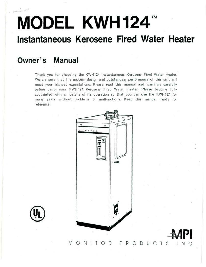
MPI KWH124 User manual

n>
MODEL
TM
InstantaneousKeroseneFiredWaterHeater
ServiceManual
MONITOR
PRODUCTS
N
C
#1123;,:
4/9f

CONTENTS
1.
Specifications
1'3
2.
SpecialPrecautions
4
3.
OperationalProcedure.
Fuel/lnstallation/Operation
5-9
4.
Freeze-Proofing
ofthe
Piping
10
5.
MaintenanceChecklist
11-12
6.
VentingInstallation
6-1
Chimney
Installation
13-14
6-2
Side
Wall
Installation
15-16
6-3
L
Type/Vertical
Venting
17-20
6-4
MPI
Venting
Kit&
Accessories
21-25
7.
Installation
of
FuelPipe
26-27
8.Hot&
ColdWaterPlumbingWork
28-29
9.
ElectricWiring
30
10.
Test
Run
,
31
11.
Operating
Information
11-1
WorkingPrinciples32-33
11-2
PerformanceData
34
11-3
ErrorCode
34
11-4
RecommendedMaintenanceProcedure
35
12.
Troubleshooting
A.)
Guideline
&
CorrectiveMeasures
36
B.)
ErrorCode
-
their
possible
causes
and
possible
solutions
37-40
"4"/"5"/"67"7"/"8"/"9"/"H"/"P"
C.)
Causes
of
troubles
and
irregularities
which
arenot
reflected
in
MonitorIndicatorLamp
1.)
Desirabletemperature
ofhot
water
is
unobtainable
41
2.)NOhot
water.Burner
does
not
ignite
42
3.)
Powerlampdoes
not
light
42
4.)
Strangesound
in
Combustion
Burner/soot
is
produced/smell
of
kerosene
......
43
5.)
Smoke
is
coming
offthe
unit.
Paint
onthe
exterior
has
burned
dueto
excessheat.
...
44

13.
FunctioningPartsData
& Howto
Check
Them
1.)
Burner
&
BurnerHead
45-46
2.)
IgnitorTransformer
,
3.)
Electrodes
4o
4.)Fan
MotorUnit
49
5.)
Water
Governor
50
6.)
MixingTank
50
7.)
HeatExchanger
51
8.)
Thermostat
For
Prevention
of
Overheating
52
9.)
OverTemperatureFuse
55
11.)
Air
PressureSwitch
56
12.)
FlowSensor57-58
13.)PrintedCircuitBoard
59
14.)
ControlPanelBaseBoard
60
15.)
ElectromagneticPumpUnit.BypassValve
61
16.)
FlameSensor
62
17.)
Nozzle
18.)
PowerTransformer
6t
19.)
FuelFilter
64
20.)
Dismounting
&
Dismantling
of
Parts/Components
65
14.
CapacityDataGraph66-69
15.
ElectricSpecifications
A.)
TimingSequenceGraph70-71
B.)
Flowchart
72
C.)
Wiring
Diagram
73
D.)
ResistanceValues
74
E.)
VoltageValues
onPCB
Connector
75
F.)
FailureMode
and
Effects
76
G.)
CircuitBlockDiagram
77
16.
SchematicDisassembly
78
17.
ServicePartsList
18.
Gauge
80-81

1
SPECIFICATION
1-1
SPECIFICATION
Model
Typ«
Combustion
Type
Air
Intake/Exhaust
Heating
Source
of
Water
Ignition
Fuel
Hot
Water
OUTPUT
Fuel
Consumption(Max)
Efficiency
Capacity
of
HeatExchanger
MaximumPressure
Applied
Minimum
Water
Flow
to
Activate
Burner
Area
of
HeatTransmission
ExteriorDimensions
Weight
Voltage/Frequency
Rated:Ampere
(Rated
PowerConsumption)
Flue
Size(Diameter)
Exhaust
Air
Temperature
Nozzle
Quantity
of
Vapor
Spray
Pattern
Spraying
Angle
Temperature
Fuse
ElectricCurrentFuse
Safety
Devices
PipeConnection
Water
Intake
Hot
Water
Outlet
Drain
Accessories(supplied)
Hot
WaterOutlet(Maximum)
DegreeRise
KWH124
PressureVapor
Indoor/Forced
Exhaust
Instantaneous
DirectConnection
of
MainSupply
High
VoltageDischargeSpark
CrystalClean
1-K
Kerosene
123.000
BTU/H
1.1GAL/H
86%*
1.057QT(1.0L)
150PSI
0.45
QAL/MIN
620
in2
35in(H)
X
1 1
.8ln(W)
X
20.9in(D)
88
Ibs.
AC
120V/60HZ
Ignition:
1.05A(127W)
Combustion:
1.00A(110W)
4
In.
482°F
0.85
GPH
Pattern
A
60"
302°F
6A
*
Safe
Ignition
*
FlameSensor
*
OverHeatProtector
'
Air
PressureSwitch
*
SurgeAbsorber
3/4
NPT
Male
3/4
NPT
Male
1/2
NPT
Mate
Fuel
Filter
Water
IntakeInsulator
Hot
WaterOutlet
Insulator
70°F
Rise
210
GALTH
80°
F
184
90°
F
164
100°
F 147
110°F
134
3.5
GA17MIN
3.07
2.73
2.45
2.23
(Maximum
hot
water
supplied
by
this
unit
Is
about
221
GAL/H.)
if
Thisrepresentsefficiencyunderlaboratory
conditions.
This
efficiency
rating
can
vary
upto4%.
"SINCE
WEARE
CONSTANTLY
IMPROVING
OUR
PRODUCTS,
ALL
SPECiRCATIONS
ARE
SUBJECT
TO
CHANGE
WITHOUT
NOTICE"
1

1
SPECIFICATION
1-2
PARTS
DESCRIPTION
•
APPEARANCE
Hot
WaterOutlet
Drain
CONTROL
PANEL
Temperature
AdjustingKnob
CONSTRUCTION
Cold
Water
Intake
Fan
Motor
Printedcircuit
Board
Hot
Water
Thermistor
Cold
Water
Intake
-Filter
ControlPanel
Front
Door
Power
Lamp
Power
Switch
Maintenance
Cover
Fuel
Filter
Connection
Junction
Box
Hot
Water
Outlet
Air
Damper
Mixing
Tank
Burner
Overheat
ProtectorThermo
HeatExchanger
TemperatureFuse

1
SPECIFICATION
1-3
UNPACKING
Unpack
unitcarefully.
The
followingparts
are
contained
inthe
package.
Locate
fuel
filter
andset
aside
touse
whenconnecting
the
fuelline.
FuelFilter
Water
IntakeInsulator
Hot
Water
OutletInsulator
NOTE:
Theseparts
are
located
inside
the
styrofoampacking
atthetopofthe
unit.
1-4
SECTIONDESIGNATIONS
&
MAINDIMENSIONS
DimensionalOutlineDrawing
(Unit:
Inches)
Hot
WaterOutlet
VentConnector
6.13.1
Cold
WaterIntake
Oil
Filter
Connection
=,
Drain
16.9
10.6
j_
10.2
20.8
1.7
I 11,

2
SPECIALPRECAUTIONS
WARNING
Use
onlycrystalclear
1 -K
kerosene.Never
use
gasoline,
whitegas,campfuel
orother
flammable
liquids.
Use
of
suchfuels
can
result
inan
explosion
and
causesevereinjury.
A
damaged
or
malfunctioningpartshould
be
discarded
andbe
replacedwith
anew
genuine
service
part.
All
repairsshould
be
left
to
professionals.Contactyourlocalauthorizedservicedealer.
-
CAUTION
-
DO
NOT
STOREflammable
liquids
or
materialssuch
as
gasoline
near
the
unit.
Make
surethat
the
flue
is
properlyinstalled
and
connected.
A
separation
inthe
flueduring
the
operation
ofthe
unit
can
causethe
release
of
exhaust
gas
into
the
room.
The
consequencescould
be
dangerous.
Turn
offthe
unit
in
case
ofan
accident
oran
emergency.Staycalm
anddonot
panic.Justturn
offthe
unit.
In
case
ofa
fuelleak,exhaustfumes
in
home,
nohot
water.Turn
off
unit.
Call
an
authorizedservice
person.
When
using
a
shower,feel
the
temperature
ofhot
waterwithyourhand
first,
beforemovingyourselfunder
thehot
water.
Avoid
theuseof
hardwater.
In
regionswherehardwater
isthe
onlysource,takeadvantage
ofa
water
softener.
This
unit
is
only
for
indooruse.Avoid
its
exposure
to
rain
or
moisture.

3
OPERATIONALPROCEDURES
3-1
FUEL
FUELTYPE
Use
only
crystal
clear
Type
1-K
Kerosene.
FUEL
SUPPLY
Precaution
-
No
water
or
debrisshould
be
allowed
to
enter
the
fueltank.Whenthese
twoare
mixedwithfuel,imperfect
combustion
can
result
thereby
shortening
the
life
ofthe
burner.
1.
Keep
the
tankfilter
cap
tight.
2.
Donot
allowtank
torun
empty.
If
the
KWH124
is
allowed
to
operatewithout
fuel,
air
must
be
purged
inthe
following
manner:
a.
Refillkerosenetank.
b.
Allow
30
minutes
after
refilling
to
activate
KWH124.
(Thisallowsfuel
to
settle.)
c.
Makesuretankvent
is
open.
d.
Openshut-offvalve
on
fueltank.
Loosen
air
purgescrew
at
fuel
filter.
Discharge
airoutofall
channelsthroughwhichfuelruns.
e.
Fill
the
bowl
ofthe
unitfuel
filter
withkerosene.
Fastenfuelpurgescrewback
in
original
position.
Handle
0-Ring
of
fuelpurgescrewcarefully.
A
damaged
0-Ring
can
cause
fuel
leakage
and
render
unitinoperative.
Don't
misplace
0-Ring.
f.
Wipe
all
fuelspills
off
thoroughly.
Fuel
purge
screw

3
OPERATIONALPROCEDURES
3-2
INSTALLATION
.
THISUNITMUSTBE
INSTALLED
IN
ACCORDANCE
WITHTHESEINSTRUCTIONS.
LOCAL
CODE,
OR-
DINANCE
AND/OR
INTHE
ABSENCE
OF
LOCAL
CODES,
THE
LATESTEDITION
OFTHE
NATIONAL
FIRE
PROTECTIONASSOCIATION(NFPA31)CODE.
J
SELECTION
OFTHE
INSTALLATIONSITE:
Choose
a
suitablesitewithwater
and
electricalconnectionsreadilyaccessible.
The
followingshould
be
taken
into
consideration
in
selecting
the
installationsite:
1.
An
indoorplacesheltered
from
weather.
2.
A
well-ventilatedplace(airintakeopeningsshould
be
provided).
3.
Side,bottom
andtop
clearancecomplywith
instructions
and
local
codes.
4.
A
placewherethere
areno
combustiblematerialsnear
the
unit.
5.
Suitable
and
non-combustiblefloor.
6.
The
fueltank
is
installed
according
to
local
codes.
7.
The
exhaust
pipe
is
installed
in
accordancewith
instructions.
8.If
water
starts
leaking,
measures
must
be
taken
so
that
it
does
not
affectotherparts
inthe
same
area
recommendedthat
a
drain
panis
placedunderneath
the
leaking
point,
until
itcanbe
repaired.
9.A
place
accessible
for
maintenanceafter
the
installation.
10.
Noiseprevention
-the
unitdoesproducesome
low
noisewhen
operating.
Carefullyconsider
the
location
for
the
installation,
if
this
is
objectionable.
11.
Unitmustalways
be
electrically
grounded.
12.
If
unit
istobe
installed
inan
alcove
ora
closet,
its
clearanceshouldcomplywithinstructions.
13.
Unitmust
be
level.
Unitperformance
is
maintainedonlywhen
itis
installed
level.
•
PROHIBITEDINSTALLATIONS
Do
not
install
the
heater
inthe
followinglocations:
(a)
In
small,
poorly
ventilated
rooms.
(b)
In
airtight
rooms.
(c)
Nearvents
for
heating
or
cooling.
(d)
In
placeswherespecialchemicals
are
used.
(e)
In
bathrooms,
bedrooms
orany
occupiedroomsnormallykept
closed.
(f)
Ina
locationwhere
itmaybe
exposed
to
freezingtemperatures.
(g)
Ina
locationwhereheater
is
subject
to
vibration.
Note:Checklocalcodes
forany
specialrequirementsconcerning
the
location
ofa
waterheater
ina
garage.
6

3
OPERATIONAL
PROCEDURES
BEFORE
THE
INSTALLATION
Important
safety.
1.
Unitshould
be
raised
off
floor
twoto
fourinches
to
preventcontactwithcombustiblematerial
and
moisture
damage
in
case
ofwet
basements.
Use
proper
and
suitablepatioblock,brick,concreteblock
or
similarnon-combustible
material.
Combustible
or
non-combustiblefloor
'/,
Non-combustible
floor
only
Bad
FT-
\
2.
Clearance
from
wall,ceilingshall
be
shown
as
"Standardclearance
for
installations."
3.
Install
an
exhaustpipe
in
accordancewith
the
instructions.
4.
Makesureproper
air
intake
and
ventilationopenings
are
provided.
a.
Indoor
air
intake:
2 air
intakeopeningsshould
be
provided
each
150
sq.in.at
minimum.
NOTE:
Air
openingswould
be
needed
if
unit
is
drawing
airoutofan
areasmallerthen
775
square
feet.
STANDARDCLEARANCE
FOR
INSTALLATION
Make
sure
to
keep
a
distancefromwalls
of
combustiblematerial.
From
Left
Side
7 in
(180
mm)
From
Right
Side
19in.
(505
mm)
From
Back
of
Heater
8 in
(205
mm)
Heater
to
ClosetDoor
29in
(735
mm)
Flue
pipe
to
CombustibleSurface,VerticallyChimneyInstallation
9 in.
(229
mm)
Fluepipe
to
CombustibleSurface,HorizontallyChimneyInstallation
9 in.
(229
mm)
Refer
to
page
16
for
minimumclearance
of
FluePipe
on
SideWallVenting.
Pages
19and20forL
Type
and
vertical
installations.
Note:Largerspacemakesservice
and
maintenanceeasier.
Space
for
service
and
maintenanceshould
be
reserved.

3
OPERATIONALPROCEDURES
3-3
OPERATION
•
ADJUSTMENT
OF
HOT
WATER
TEMPERATURES
a.
Thermostat
has
been
setat
factory
to
about
104°
F
(LOW).
b.
Slide
"HotWaterTemperature
Adjuster"
knob
up
toward
"High"
to
raise
water
temperature.
Slide
knobdown
toward
"Low"
to
reducetemperature.
c.
Whenadjusting
hot
water
temperaturewith
not-cold
water
mixingvalve,control
the
amount
of
cold
water
frommain
supplywithoutchanging
the
amount
ofhot
waterbeingsupplied.
if
Knob
at
position
"HIGH"
provides
hot
water
ata
temper-
ature
around
167°F.
Knob
at
position"MED"provides
hot
water
ata
temper-
ature
around
130°
F.
Knob
at
position"LOW"provides
hot
water
ata
temper-
ature
around
104°F.
HIGH
n
LOW
LJ
MED.
WARNING
*
Hightemperaturesettingincreases
the
risk
of
SCALDinjury.
*
Households
with
small
children
or
invalids
may
require
a
120°
For
lower
thermostat
setting
(to
prevent
accidentalcontactwith"HOT"water.)
NOTE-
*
Seasonalchange
in
temperature
of
waterfrommainwater
supply
results
in
different
hot
watertemperatures
supplied.
Usehot
watersupply
tapto
control
hot
watertemperature,
or
readjustthermostatsetting.
UNITSHUT
OFF
1.
Shut
offhot
water
supply
tapand
burnerwillautomaticallyextinguish.
(Post
purge
fan
will
run
approximately
150
secondsaftershutoff.)
2.
Press
and
turn
off
"Power"
whenunit
isnot
going
tobe
used
foran
extendedtime.
"Power"
lamp
gof
8

3
OPERATIONALPROCEDURES
3-4
WARNINGS
BURNS
Don't
touch
the
flue.
The
flue
reaches
a
high
temperature.Protectyourselffrom
potential
burns.
WATER
FOR
DRINKING
The
quality
of
waterfrom
unit
may
changedepending
on
water
being
supplied
from
main,
and
deterioration
of
piping
material,
scale,
etc.
Never
use
waterthat
has
remained
stagnant
in
heatexchanger
and
pipes
for
long
periods
as
drinking
water.Turn
water
onfora
couple
of
minutes
before
drinking.
SHOWER
Feeltemperature
ofhot
waterwithyourhandbeforeenteringshower
stall.
KEEP
DRAINVALVESHUTWHILEUNIT
IS
OPERATING
Openingdrainvalve
while
unit
isin
operation
will
overheat
unit
andcan
result
in
possible
heatexchangerdamage
and
blowntemperaturefuses.
LIGHTNING
Lightning
may
cause
a
temporarypowersurge,which
may
damagesome
electronic
parts.Wherethere
is
thunderstormactivity,
install
a
surgeprotector
in
power
circuit.
WHEN
UNITWILL
NOTBE
USED
FORAN
EXTENDEDPERIOD
OF
TIME
TAKE
THE
FOLLOWINGMEASURES:
1.
Closefuelsupplyvalve
at
fuel
tank.
2.
Turn"Power"
switch
off.
3.
Purgewater
from
unit
(See
instructions
on
Page
10.)
9

4
FREEZE-PROOFING
OFTHE
PIPING
Freezingmust
be
anticipated,
not
only
inthe
northernstates,
butin
otherareas
as
well.
Therefore,care
must
be
taken
to
ensure
the
lines,valves
and
unit
donot
freeze.
Water
should
notbe
allowed
to
freeze
inthe
supply
orhot
waterpipes
in
winter.
If
waterfreezes
inthe
supply
and
hot
water
supplypipes
in
winter,
frozen
pipes
could
rupture
and
leak.
Repairs
to
unitwithrupturedpipescould
be
costly.Suchdamages
arenot
covered
bythe
warranty.
The
following
preventive
measuresshould
be
followed:
•
RUNNING
WATER
This
methodwillhelp
to
prevent
water
from
freezingthroughoutunit's
systems
including
pipes
for
inlet
water
and
hot
watersupplies
as
well
as
valves.
1.
Turn"Power"switch
on
controlpanel
tooff
position.
2.
Open
ahot
water
tapand
allow
a
stream
to
flow
continuously
at
about.
1
gal/min.
Be
sure
to
checkthat
water
continues
torun
during
the
periodthatfreezing
may
occur.
•
PURGINGWATER
Thismethod
is
usefulwhen
unit
isnot
going
tobe
used
for
extended
periods
of
time.
1.
Shut
off
electricalpower.Turn
off
water
supplyvalve
at
unit.
2.
Openfully
allhot
water
faucets
(including
the
shower).
3.
Opendrainvalve
of
heatexchanger.
Open
inlet
waterscreen
and
release
the
pressure
relief
valve.
Allow
water
to
drainfrominsideheatexchanger.
"CAUTION-
When
turning
on
unit
in
cold
weather,openwaterfaucet
and
makesurethatwatercomesout.
If
waterdoes
not
run
smoothly
or
does
not
come
outat
all,chances
are
water
is
frozen.Wait
until
waterstarts
running
smoothly,
and
thenturnunit
on.
10

5
MAINTENANCECHECKLIST
It
is
recommendedthat
the
unit
is
inspected
and
cleanedonce
orsoa
year
to
ensure
its
longlife,
•
FLAMMABLES
OR
DUST
Keep
thetopand
vicinity
of
unit
clean.
Keep
flammables
and
dangerousitemsawayfrom
unit.
•
FUELLEAKAGE,SPILLS
AND
STAINS
Make
sure
all
fuelconnections
are
tight
andarenot
leaking.
Any
spills
or
stains
by
unitindicate
a
leak
and
must
be
corrected.
•
FUELPIPESREPLACEMENT
Checkfuel
pipes
at
least
onea
year
for
distortions
and/or
cracks.Contact
authorized
servicedealer
for
re-
placement
of
defective
pipes.
•
WATER
IN
FUELTANK
Water
and
dust
can
easily
go
intofuel
tank.
Afteraccumulating
inthe
tank,
they
may
flowintoburner
and
cause
imperfectcombustion.Check
if
there
isany
water
inthe
tank
at
leastevery
six
months
by
checking
the
fuelfiltercanister
at
tank.Have
any
waterremoved
byan
authorizedserviceperson.
•
FLUE
AND
ITS
VICINITY
Periodically,
make
sure
thatthere
areno
flammablesaround
and
aboveflue.Also,makesureflue
is
properly
installed
and
maintained.
•
CLEANING
HEATEXCHANGER
Drainwaterfromheatexchanger
at
least
onea
year.
1.
Shutwatersupplyvalve
at
main.
2.
Open
hot
watersupplyfaucet.
3.
Open
drain
valve
at
heatexchanger.
Also,
open
inlet
waterfilter
and
pressurereleasevalve.Then,drain
water
fromheatexchanger.
•
CLEANINGINLET
WATER
FILTER
Check
onceeverythreemonths
and
removedebris
\y/
Cold
water
intake
gathered
in
the
inletwater
filter.
[Q/
inlet
Water
Filter
1.
Shutwatersupplyvalve
at
main.
S^T^"?^
2.
Open
hot
watersupplyfaucet.
3.
Open
drain
valve
at
heatexchanger.
Then,removeinletwater
filter
and
wash
and
clean
it.
CAUTION
If
lime
has
accumulated,remove
it
with
a
commercialcompound
for
dissolvinglime.Check
water
soften-
ing
equipment
if
lime
is
found
inthe
filter.
11

5
MAINTENANCECHECKLIST
CLEANING
FUELFILTER
To
be
done
by
authorizedserviceperson.Check
at
least
every
six
months
toseeif
debris
and/or
water
has
gathered
in
fuelfilter.
1.
Shutfuelsupplyvalve
on
fueltank.
Turn
cup
counterclockwise
to
remove
it
from
the
assembly.
Dumpwater
and
debrisfromcup.
2.
Pull
off
element.
Clean
it
withkerosene.
3.
Reassemblefuelfilter.
Purge
air
fromfuel
fitter.
EXCESSIVE
PRESSURERELIEF
VALVE
Once
a
year,makesurethat
the
pressure
relief
valve
(installed
on
water
supply
piping)
is
functioning.
12

6
VENTINGINSTALLATION
6-1
CHIMNEYINSTALLATION
•
FITTING
THE
FLUE
IMPORTANT'
THISUNITREQUIRES
A
DRAFT
(AT
FLUECONNECTION
OFTHE
UNIT)
OF
-2mmH20
to
-5mmH20
TO
OPERATE
NORMALLY.
Use
fluepipes
of4"
inside
diameter.
Note:
Itmaybe
necessary
to
install
a
Draft
Regulator
inthe
flue
to
obtain
the
recommended
operating
draft.
\
\
\
\
\\\\\\v\\
\ \ \ \ \ \ V
\_
\
A
A
9"MIN
FromCombustible
Material
Pitch
Flue1/4"
Per
FootUpward
9"
MIN
10'
MAX
_
Overall
Length
11
Of
Flue
Pipe
1/2'
MAX
Chimney
Installation
Example.
13

6
VENTINGINSTALLATION
•
GUIDELINE
FOR
ATTACHING
THE
FLUE
1.
Donot
make
any
changes
tothe
diameter
ofthe
flue
piping.
2.
Use
durablematerials
forthe
fluesuch
as
doublewall
pipes
withstainlesssteel.
3.
Seal
the
connections
ofthe
flue.
4.
Ensurethatminimumdistances
aremet
betweenflue
piping
and
walls
and
ceiling.
5.
Double
wall,
L-typefluepipes
are
recommended
to
preventinjury
or
bums,
if
there
is
contact
with
flue.
Chimney
Connection
Check
localcodes
and
ordinances.
IMPORTANT
GUIDELINE>
1.
The
flue
piping
ofthe
unit
should
beas
short
as
possible,
and
pitch
1/4"
per
foot
up
towardchimney.
Donot
exceed
10
feet
overalllength
of
flue
pipe.
2.Donotuse
morethan
two
bends
inthe
piping.
Chimney
penetration
isnot
considered
a
bend.
3.The
piping,
wheninserted
into
the
chimney
should
not
extend1/2"beyond
the
inside
surface
ofthe
chimnr
The
area
around
of
flue
piping
should
be
sealedwhere
it
enters
the
chimney.Refer
tothe
drawing
belt
Seal
1/2"
14

6
VENTINGINSTALLATION
6-2
SIDEWALL
INSTALLATION
IMPORTANT
1.
Use
only
MPI
KWH
Vent
Kitand
Accessories
for
SideWall,
Vertical,
L-TypeVenting.
2.
Thisunitmust
be
installed
in
accordancewiththeseinstructions,
local
code,
ordinanceand/or
inthe
absence
of
local
codes,
the
latestedition
ofThe
National
FireProtectionAssociation(NFPA
31)
code.
GUIDELINES
FOR
ATTACHING
THE
FLUE:
1.
Donot
make
any
changes
tothe
diameter
ofthe
flue
piping.
2.
Seal
and
lock
the
connections
ofthe
flue.
3.
Useanendcapto
protect
the
flue
fromrain
and
wind
coming
in.
4.
An
insulatedwallthimble
is
required
for
inserting
the
fluethrough
any
combustiblematerial.
5.
Ensurethatminimumdistances
aremet
betweenfluepipes
and
walls
and
ceilings.
6.
Flue
piping
usedthrough
the
wall
should
be
pitched
down1/4"
per
foottoward
outside.
(SideWallVenting.)
15

6
VENTINGINSTALLATION
SIDEWALL
VENTING-FITTING
THE
FLUE
IMPORTANT
ExtensionLimits
ofthe
Rue
Length
ofthe
Rue
10
feet
16
feet
Number
of
Bends
2
1
Note:
Extensionlimits
donot
includepipeadaptorelbow
andend
cap.
INSTALLATION
EXAMPLE
(1)
-1
BEND
Use
Only
MPI
Venting
Kit
(Model
MPI-KWH
Vent
Kit)
Material
3"
(MIN)Clearance
From
Combustible
9"
(MIN)
Clearance
7"
(MIN)
__
Clearance
9"
(MIN)
Clearance
Endcap
(Horizontal
VentCap)
Wall
thimble
-6"(MIN)Clearance
PitchFlue1/4"downward
per
foot
NOTE:
•
Maintain
3"
min.
clearancearoundfluepipefrom
any
combustiblematerial.
•
Maintain
9"
min.clearancearound
endcapand6"
min.clearanceoutsidewall.
•Endcapisnot
considered
a
bend.
Inthe
drawingshown
above,
the
number
of
bends
is
one.
16

6
VENTINGINSTALLATION
INSTALLATIONEXAMPLE
(2)
-
2
BENDS
Vent
Cap
(Horizontal
Vent
cap)
Wall
Thimble
Top
View
Elbow
Elbow
Elbow
Pipe
Adapter
Side
View
D
Elbow
Wall
Thimble
NOTE:
Maintain
all
min.
clearancesstated
in
installation
example
(1).
Possible
Applications
- 2
bends.
(1)Up,
across,
and
back
(2)
Up,
back,
and
across
(3)
Back
and
across
(4)
Across
and
back
Length
variation
may
vary
depending
on
place
of
installation.
Length
should
not
exceedextensionlimits
and
no
morethan
2
bends
17
Other manuals for KWH124
1
Table of contents
Other MPI Water Heater manuals
Popular Water Heater manuals by other brands
PVI Industries
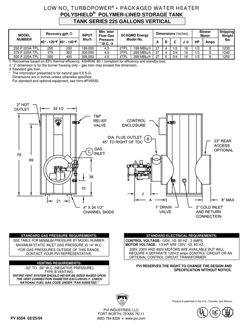
PVI Industries TURBOPOWER 1000 P 225A-TPL specification

Panasonic
Panasonic DH-6SM1 Operating and installation instructions

C&M
C&M Britony II T Installation and servicing instructions

Quick
Quick B3 user manual

HTP
HTP SSC-35 Installation start-up maintenance parts

Hayward
Hayward PRO GRID C9002SEP owner's guide

fothermo
fothermo PSU-12 Installation and operation instructions

auer
auer Edel Air 200 User instruction manual

Giant
Giant UGC55S-100 Installation & maintenance guide

Nibe
Nibe EMINENT-E/CU/R 35 installation instructions

Rinnai
Rinnai Sensei RU160i Installation and operation manual

Santon
Santon PowerPack Fitting instructions