Mr Beam Shield User manual
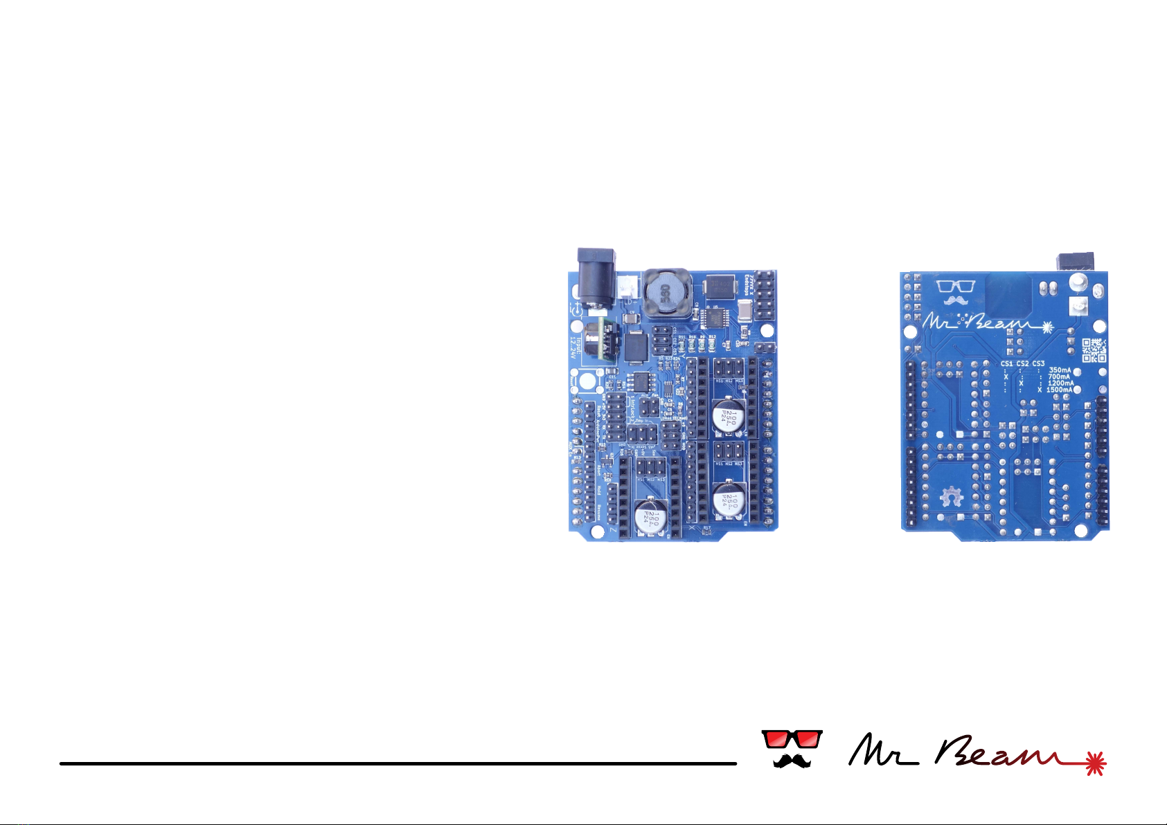
backfront
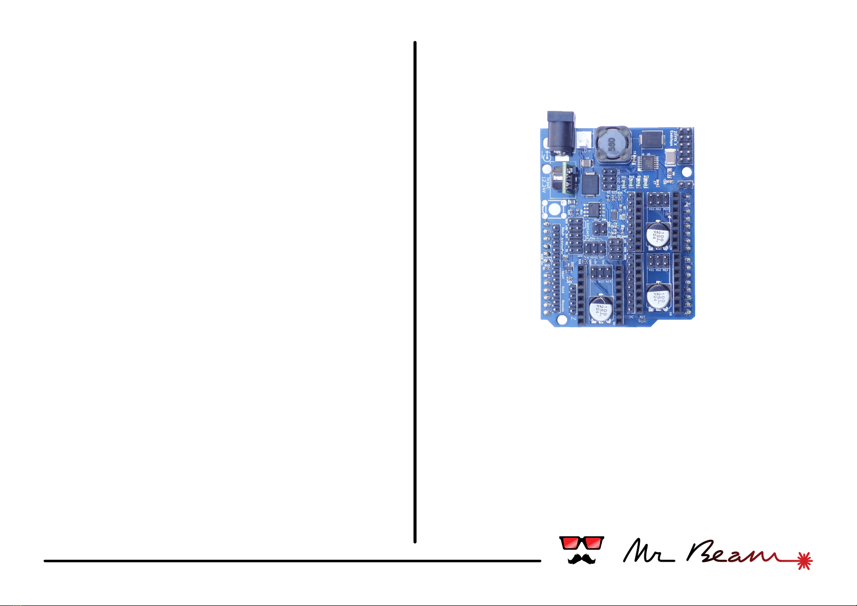
Mr Beam Shield - Instructions
#01 laser driver
#02 power source
#03 axes & motors
#04 miscellaneous
#05 safety
#06 usage & appendix
#about
What is it?
The Mr Beam Shield was developed within the
Kickstarter project "Mr Beam - a Portable Laser
Cutter and Engraver Kit" (see http://kck.st/1j4BQiz).
Beeing compatible to the grbl firmware (http://
bengler.no/grbl), it combines a laser diode driver with
up to 3 stepper motor drivers on an Arduino Uno
shield. We recommend the usage of our Mr Beam
grbl fork which is already configured to the shields
features. You can find it at https://github.com/
mrbeam .
What can I build with it?
Originally the shield was designed for the Mr Beam
laser cutter kit, but it can be used for every laser
device which uses stepper motors in the mechanics.
Besides laser cutters this can be laser sintering 3D
printers, 3D scanners, laser projectors or other
robots.
Thank you & Have fun!
By purchasing this shield you have supported a piece
of open hardware - thank you!
We enjoyed the development of it and will continue
improving it. We hope you find our work useful and it
will help you to be creative. Whatever you do, take
care about yourself and others. We would love to see
your work in the social networks. Tag it with
#mrbeam to catch our attention.
Have fun!
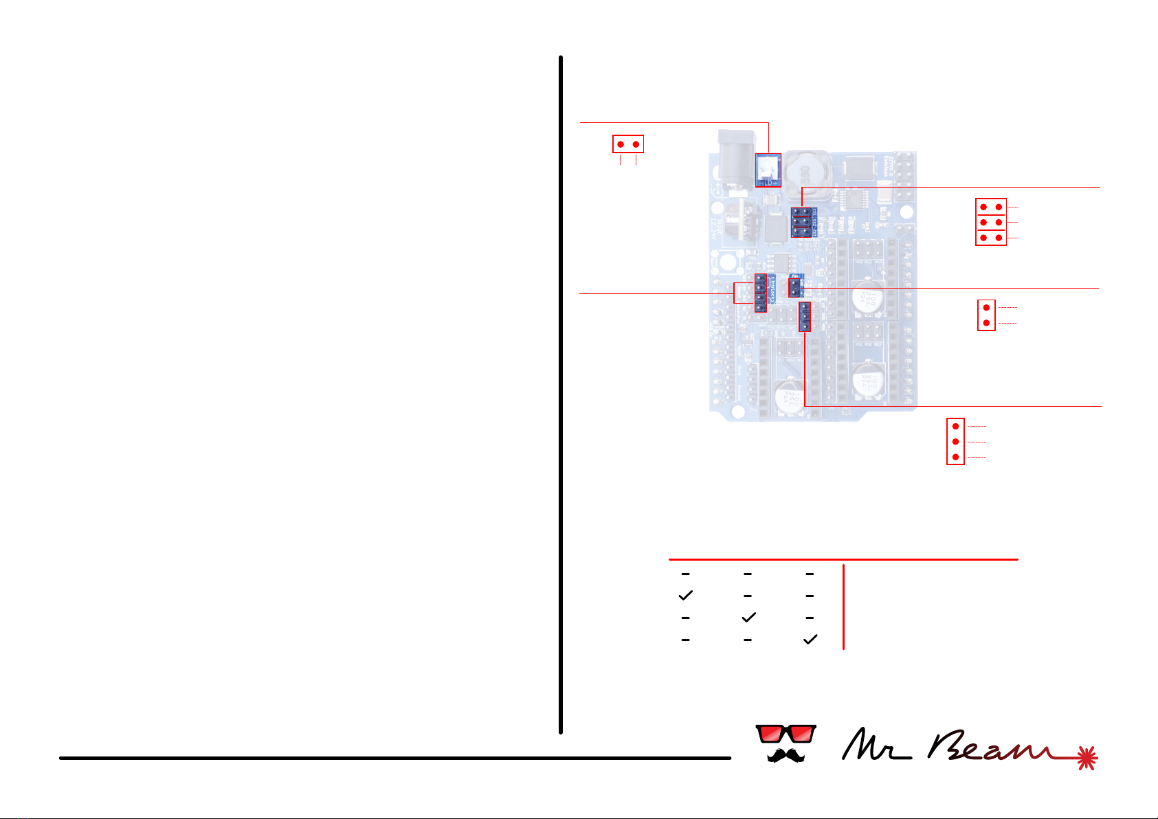
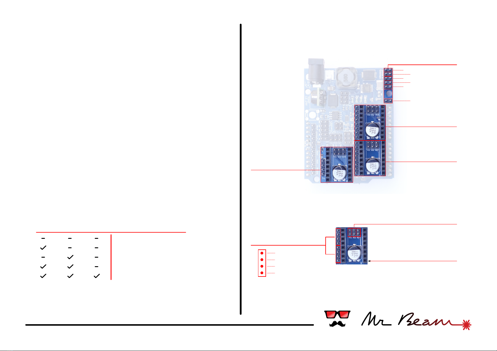
#01 laser driver
Current Selector
2x Interlock
Laser Diode
-
+
Laser diode driver
The Mr Beam Shield features a dimmable and
efficient laser diode driver with a maximum output of
1500mA. The output current has to be set before
connecting a laser diode.
Check the data sheet of your diode for the maximum
current and place the jumper according to the
following table on the right
Setting the current too high may destroy your laser
diode.
Before connecting the laser diode check twice the
polarity of your diode, the cable and the connectors in
between. A false polarity will destroy your diode.
Interlock connectors
The shield provides 2 connectors for interlock
switches or sensors. Both have to be closed for
operating the laser.
Cooling Fan
Connect a cooling fan at this two pins. The voltage
supplied at the + pin equals the input voltage from
your power supply. The fan can be switched with the
commands M08 (on) and M09 (off).
CS1 CS2 CS3 Max Output Current
350mA
700mA
1200mA
1500mA
Cooling Fan
-+
Laser intensity
+5v
ground
pwm signal
CS1
CS2
CS3
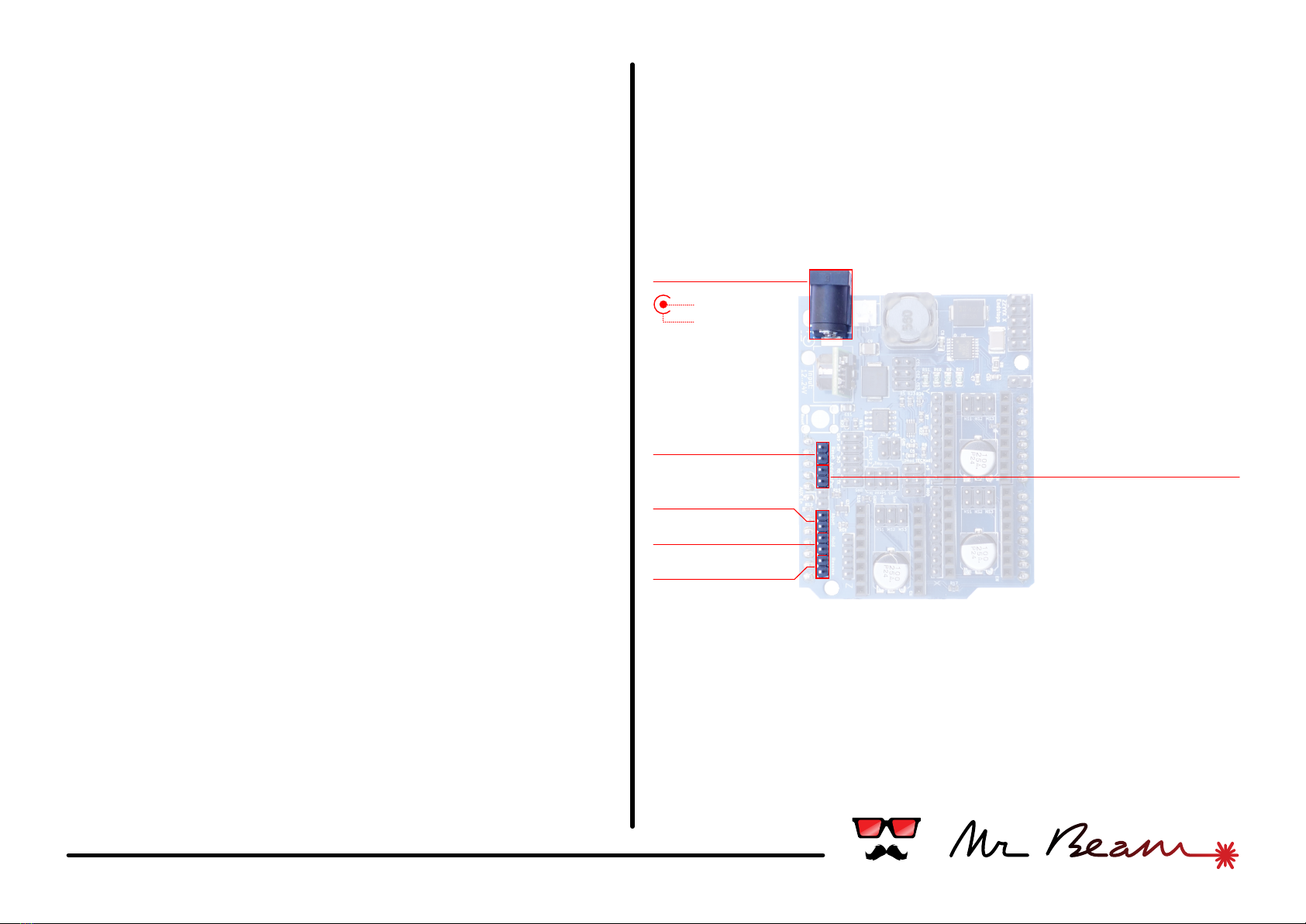
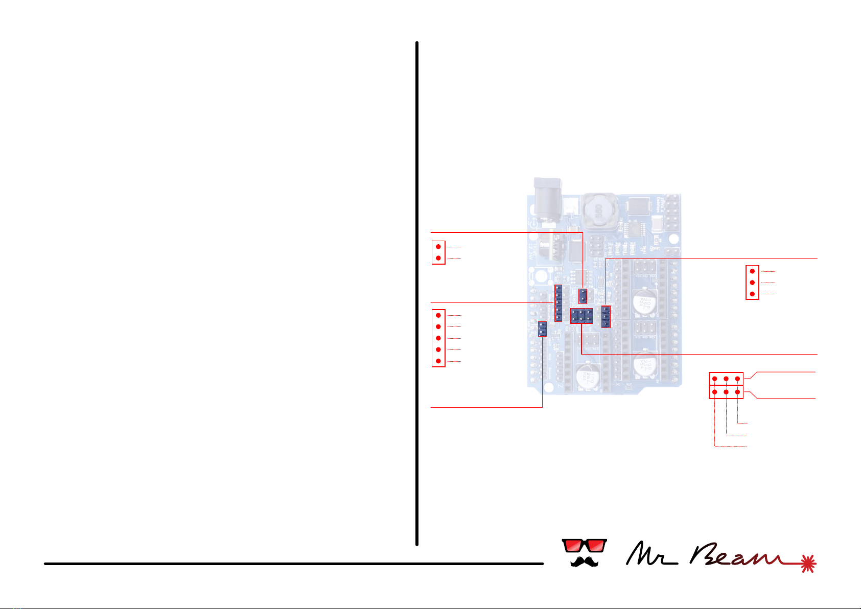
#02 power & control
Power in
Power in
The shield supports a wide input voltage between 12V
and 24V. When using your own power source please
check that the power jack has the correct polarity.
Reset, Cancel, Hold, Resume Buttons
For easy wiring the shield has a dedicated connector
for each control button supported by the GRBL
firmware. Just plug in the button's cables - that's it.
Arduino Power
This little feature powers the Arduino under the
shield with the supply voltage from the power supply
connected to the shield. A voltage converter provides
5V output to the Arduino with a maximum of 1.5A. It is
even enough to power an attached Raspberry via USB
as well.
To enable this feature, place a jumper on the two
pins.
Arduino Power
Reset
Cancel
Hold
Resume
-
+
#03 axes & motors
Y-Axis
X-Axis
Z-Axis
Endstops
2x Motor
Micro stepping
Enable pin
Driver socket
Z1
Y1
X1
Z2
Y2
X2
Motor axes:
The Mr Beam Shield can control up to 3 independent
axes. It has 3 sockets compatible with Pololu/
Stepstick stepper drivers like the ones used on many
3D-printers.
While the Z axis has only a single stepper motor, the
other axes have double motor connectors. This allows
to drive two steppers with a single driver and is useful
for a double motor axis like the Y-axis on a Mr Beam
Senior. The connectors are using the reprap-style pin
order (1b, 1a, 2a, 2b). Turning the connector 180°
inverts the motor direction.
Check the orientation of a stepper driver before
plugging it in. The "enable" pin of the driver is
marked on the shield as well.
The 3 jumpers marked with MS1, MS2, MS3 configure
the micro stepping mode of the driver. Depending on
the driver's chipset the modes may differ.
This table shows the settings for the common A4988
chip:
Endstops:
The shield provides 2 endstop connectors for each
axis. Micro switches can be attached directly,
MS1 MS2 MS3 Microstep Resolution
Full step
Half step
Quarter step
Eighth step
Sixteenth step
1b
1a
2a
2b
#04 miscellaneous
A5 Mode
The assignment of the Arduino pin A5 is configurable. It
can be used to switch the power of the AUX connector or
as an additional sensor input.
Place a jumper to enable the AUX power out, leave it open
for using the sensor 2.
AUX
This two pins are an additional switchable power outlet. It
switches directly the input power and can handle a
maximum of 1A.
When using it ensure that the A5 mode jumper is closed.
Serial
The serial rx/tx pins from the Arduino have its own
connector here. The RX/TX pins have 3.3v logic levels, but it
is no problem to use them with 5v as well if the
counterpart is flexible as well. Additionally there are both
voltage levels and ground available as well.
Sensor Input
Though the analog Arduino pins A4 and A5 are not used in
standard GRBL firmware, the shield is ready for future
developments and provides own connectors for them. In
combination with a +5v and ground pin for each, it is easy
to plug in common sensors.
When using the sensor 2 ensure that the A5 mode jumper
is open.
TEC Signal
Another thing for future development. Currently not
supported.
TEC Signal
Serial
AUX
A5 Mode
Sensor Input
+5v
ground
signal
sense
+5v
ground
Sensor 1
Sensor 2
-
+
ground
+5v
+3.3v
rx
tx
#05 safety
Laser Classification
IEC 60825 classiefies laser products into different
categories depending on light emitted, wavelength and eye
safety. Classes for typical laser diodes are given below.
Class 2, 2M / US Class IIa, II
Caution, normally visible laser light less than 1.0mW.
Considered eye safe, normal exposure to this type of beam
will not cause permanent damage to the retina
Class 3R / US Class IIIa
Danger, visible laser light between 1.0mW and 5.0mW.
Considered eye safe with caution. Focusing of this light into
the eye could cause some damage.
Class 3B / US Class IIIb
Danger, infrared (IR) and high power visible lasers <
500mW. Considered dangerous to the retina if directly
esposed.
Class 4 / US Class IV
Danger, laser output power greater than 500mW. Class 4
lasers are capable of causing injury to both the eye and
skin and will also present a fire hazard if sufficiently high
output powers are used.
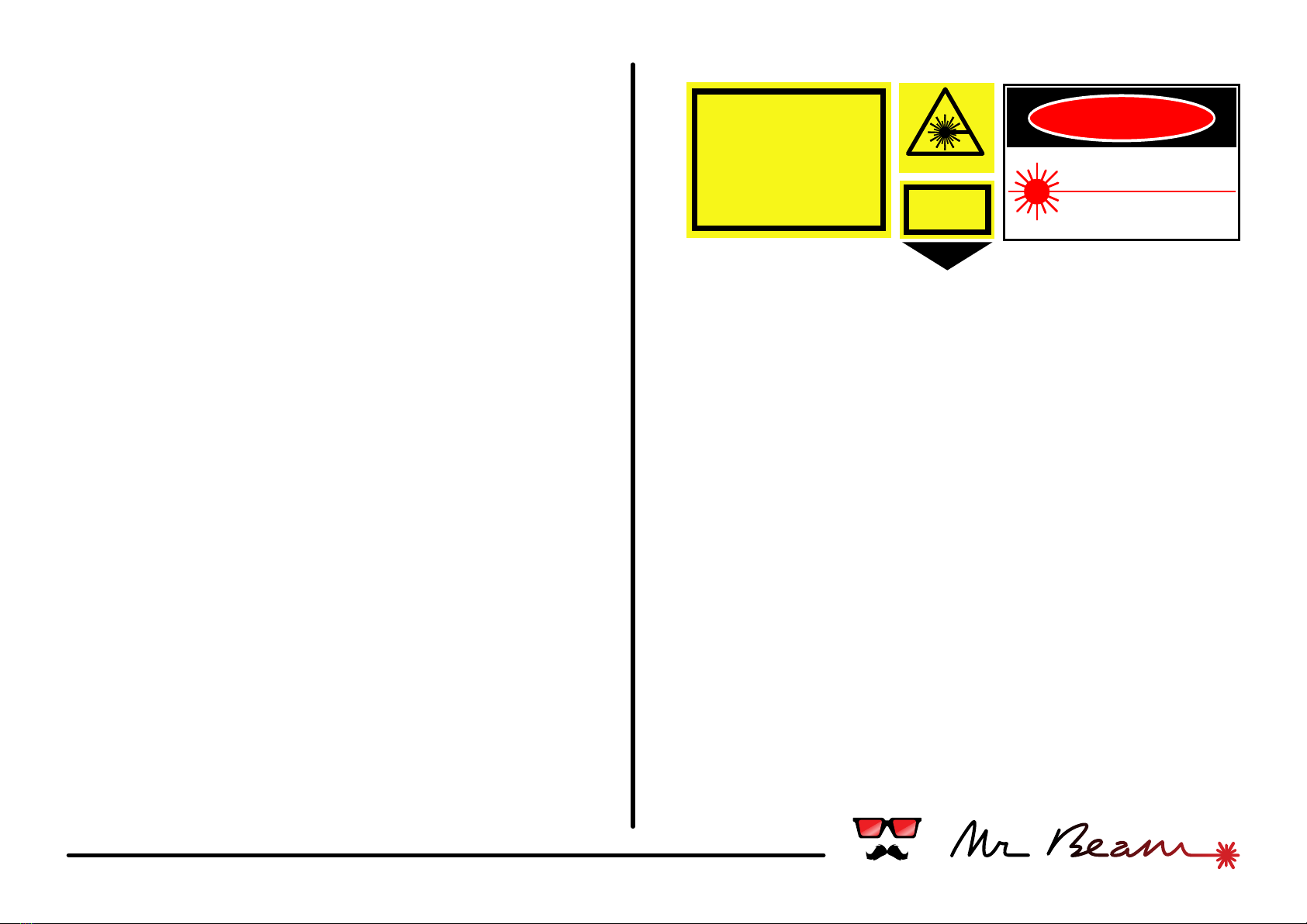
You are responsible for the correct classification of your
device. Additionally you have to put all safety labels on it
according to your local regulations. Some examples of
such labels are shown on the right.
Check your local regulations for chosing the right ones.
LASER RADIATION
LASER RADIATION
AVOID EYE OR SKIN EXPOSURE TO
DIRECT OR SCATTERED
RADIATION
CLASS 4 LASER PRODUCT
Max Power: 1000mW
Wavelength: 400-695nm
Classified according IEC 60825-1
2007
LASER
APERTURE
Safety Glasses
Laser light is very intense. The natural winking reflex is not
able to protect your eye. Always protect your eyes with
appropriate safety glasses when operating a laser.
Appropriate laser safety glasses need to block the laser's
wavelength sufficiently. Sunglasses or just dark glasses
are not able to do that. In addition to safety glasses you
should consider to build a safety housing around your laser
device.
Be Responsible
Always take care about yourself and others. Operate lasers
with maximum attention at any time.
Respect Local Laws and Regulations
Almost every country has its own laws and regulations for
operating a laser. You are fully responsible to respect and
act in compliance with these.
LASER RADIATION
AVOID EYE OR SKIN EXPOSURE
TO DIRECT OR SCATTERED RADIATION
DIODE LASER
1000mW MAX at 445 nm
CLASS IV LASER PRODUCT
DANGER

#06 usage & appendix
Usage
The shield was designed to be used with the popular grbl firmware. We
recommend our own fork at https://github.com/mrbeam which is
preconfigured to the shield's pin layout and features.
Flashing GRBL
Checkout https://github.com/grbl/grbl/wiki/Flashing-Grbl-to-an-
Arduino for detailed multiplatform instructions how to flash the
firmware on your Arduino.
Use the precompiled grbl.hex from https://github.com/mrbeam
G-Code
In addition to the standard G-code supported by grbl (see http://
www.shapeoko.com/wiki/index.php/G-Code#G-
code_supported_by_Grbl) the Mr Beam version has reused some
commands for controlling the laser intensity.
Replace # with appropriate parameter values in the examples below.
Laser Control
M03 S### : switch laser to intensity. Intensity is number between 0 and
255. If the laser was switched off before it will be switched on.
M05 : switch laser off.
Fan Control
M08 : switch cooling fan on.
M09: switch cooling fan off.
Movement
$H : do a homing cycle
G21 : switch to mm units
G90 : switch to absolute coordinates
G92 X0 Y0 Z0 : set coordinate origin
G0 X# Y# : rapid positioning move
G1 X# Y# : move to given position with the current feedrate
F### : set feedrate
Additional Information Resources
The internet is full of information about laser technology and safety.
Some (but not all) information resources are listed below:
Safe usage of lasers
http://en.wikipedia.org/wiki/Laser_safety
Safety glasses
http://www.thorlabs.com
http://www.noirlaser.com
http://www.lasersafetyindustries.com
and many more.
Laser cutting
http://atxhackerspace.org/wiki/Laser_Cutter_Materials
GRBL / G-Code
http://bengler.no/grbl
http://en.wikipedia.org/wiki/G-code
Accessories
http://www.pololu.com/category/120/stepper-motor-drivers
http://www.watterott.com/en/Interfaces/Motor-Controllers/Stepper
https://www.lasertack.com/
http://www.insaneware.de/
https://sites.google.com/site/dtrlpf/
http://odicforce.com/
Table of contents


