Acorp 4PM266M User manual

The information presented in this publication has been
made carefully for reliability; however, no responsibility
is assumed for inaccuracies. Specifications are subject
to change without notice.
IBM, PC/AT, and PC/XT are trademarks of
International Business Machines Corporation.
Socket478 is a trademark of Intel Corporation
AWARD is a registered trademark of Phoenix
Software Inc.
MS-DOS and WINDOWS NT are registered
trademarks of Microsoft Corporation.
Trademarks and/or registered trademarks are the
properties of their respective owners.
User's Manual Version 1.0
4PM266M
i

TT
TT
Table of Contentsable of Contents
able of Contentsable of Contents
able of Contents
IntrnctctinnIntrnctctinn
Intrnctctinn
1. Mnthdranarc Ddrcriotinn1. Mnthdranarc Ddrcriotinn
1. Mnthdranarc Ddrcriotinn
1.1 Intrnctctinn1-1
1.1Packagd Cnntdntr1-1
1.3 Fdattrdr1-1
1.4 4PM166M Mnthdranarc Layntt1-4
1.5 CPU Inrtallatinn1-6
1.6 DDR RDRAM Inrtallatinn1-8
1.7 Cnnndctnrr& Jtmodr Rdtting
1.7.1 Back Pandl Cnnndctnrr
1.7.1.1 PR.1 Mntrd.Kdyanarc CNMM.1-9
1.7.1.1URB Pnrt Cnnndctnr (URB1(1-9
1.7.1.3 LAMPnrt Cnnndctnr1-9
1.7.1.4 Rdrial Intdreacd onrt (CNM1(1-10
1.7.1.5 VGA Intdreacd Cnnndctnr1-10
1.7.1.6 Paralldl Intdreacd onrt 1-10
1.7.1.7 Jnyrtick .Mici Cnnndctnr1-10
1.7.1.8 AtcinPnrt Cnnndctnr1-10
1.7.1ATX 4-oin.10-oin Pnwdr Cnnn.: CM1.CM31-11
1.7.3 Flnooy Dirk Cnnndctnr: FDC 1-11
1.7.4 Harc Dirk Cnnndctnrr: IDD1.IDD1 1-11
1.7.5 CPU Fan Cnnndctnrr: FAM1~3 1-11
1.7.6 CD-Atcin-IMCnnndctnrr: CDIM1.CDIM1 1-13
1.7.7 Wakd-Nn-LAMHdacdr: WNL 1-14
1.7.8 Wakd-Nn-Mncdm Hdacdr: WNM 1-14
1.7.9 Frnnt URB1.1 Cnnndctnrr: URB1.31-15
1.7.10 Frnnt Pandl Cnnndctnr: PAMDL1-15
1.7.11 CMNRFtnctinn Rdldctinn: JBAT1 1-17
1.7.11CPU Clnck Frdqtdncy Rdtting: J7 1-18
1.7.13 IR Inerardc Cnnndctnr: IR 1-18
1.7.14 Rmart Pandl Ftnctinn (notinnal(1-19
ii

TT
TT
Table of Contentsable of Contents
able of Contentsable of Contents
able of Contents
1.7.14.1 Pnrt 80 Ddatg Ftnctinn(RP-J6(1-19
1.7.14.1Rdcnnc BINRCnnndctnr(RP-J1(1-10
1.7.14.3 AUX LIMD Cnnndctnr(RP-J5(1-10
1.7.14.4 Frnnt CNM1Hdacdr Cnnn.(RP-J7(1-10
1.7.14.5 Frnnt URB3,4 Hdacdr Cnnn.(RP-J8(1-10
1. BINRRdtto1. BINRRdtto
1. BINRRdtto
1.1 Main Mdnt1-4
1.1Rtancarc CMNRFdattrdr1-7
1.3 Acuancdc BINRFdattrdr1-10
1.4 Acuancdc Chiordt Fdattrdr1-14
1.5 Intdgratdc Pdriohdralr1-19
1.6 Pnwdr Managdmdnt Rdtto1-15
1.7 PnP.PCI Cnneigtratinnr1-30
1.8 PC Hdalth Rtattr 1-33
1.9 Frdqtdncy.Vnltagd Cnntrnl1-35
1.10 Lnac Fail-Raed Ddeatltr1-36
1.11 Lnac Notimizdc Ddeatltr1-37
1.11Rdt Rtodruirnr.trdr Parrwnrc 1-38
1.13 Raud & Dxit Rdtto1-40
1.14 Dxit Withntt Rauing 1-41
3. Driudr Inrtallatinn3. Driudr Inrtallatinn
3. Driudr Inrtallatinn
3.1 Main Mdnt3-1
3.1Inrtalling VIA 4 in 1 Driudr 3-1
3.3 Inrtalling AtcinDriudr 3-3
3.4 Inrtalling VGA Driudr 3-5
3.5 Inrtalling LAMDriudr 3-7
a. Aoodncixa. Aoodncix
a. Aoodncix
iii

1-11-1
1-11-1
1-1
Chaosdr 1 Mnshdranarc CdrbrhoshnnChaosdr 1 Mnshdranarc Cdrbrhoshnn
Chaosdr 1 Mnshdranarc Cdrbrhoshnn
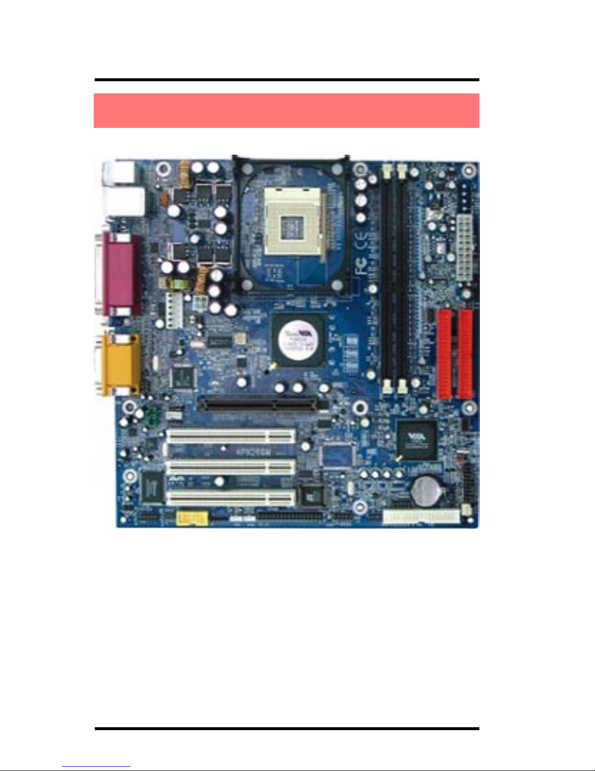
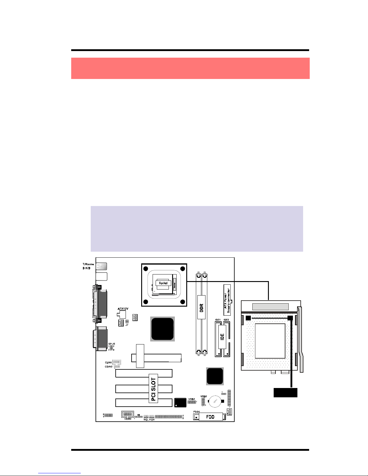
The 4PM266M motherboard is designed for using Intel P4
Front Side Bus Frequency 400MHz CPU, which utilize the Socket-
478 design and the memory size expandable to 2.0GB.
This motherboard use the latest VIA P4M266 chipset, appling
266MHz (Double Data Rate) Front Side Bus frequency and 266MHz
memory interface delivers a clear upgrade path to the future gen-
eration of 266MHz processors, PC-1600/PC-2100 DDR SDRAM.
The 4PM266M motherboard offers ULTRA ATA 100/133 to pro-
vide speedier HDD throughout that boosts overall system
performance.
It is ideal for multi-tasking and fully supporting MS-DOS,
Windows, Windows NT , Windows ME, Windows 2000, Novell,
OS/2, Windows95/98, Windows 98SE, Windows XP, UNIX, Liunx
, SCO UNIX etc. This manual also explains how to install the
mainboard for operation, and how to setup your CMOS
configuration with the BIOS setup program.
1
Chapter
●HDD UDMA66/100 Cable.
●FDD Cable.
●FlashMemorywrittenforBIOS update.
●USB2 Cable (Optional)(Optional)
(Optional)(Optional)
(Optional).
●Fully Setup CDDriverbuilt inutility(Ghost, Antivirus,
AdobeAcrobat).
●Manual.
1.1 Introduction
1.2 Package Contents

1-11-1
1-11-1
1-1
Chaosdr 1 Mnshdranarc CdrbrhoshnnChaosdr 1 Mnshdranarc Cdrbrhoshnn
Chaosdr 1 Mnshdranarc Cdrbrhoshnn
CPU Processor
●400MHz System Interfacespeed orhigher.
●Single Socket 478 forIntel P4TMup to 2.2GHz orhigher
(Northwood Processor).
●SupportIntel NetburstTMMicro-architecture.
Chipset
●VIA P4M266 NorthBridge.
●VIA VT8233A SouthBridge.
PCI/AGP Speed
●Supports 33MHz PCIBus speed.
●Supports AGP 66 MHz for2X/4X device.
DDR SDRAM Memory
●Supports 64/128/256/512....MBDDR module socket.
●Supports Synchronous DRAM(2.5V)
●Supports amaximum memorysize of2GB withDDR
SDRAM.
Bus Slots
●ProvideoneAGP slot.
●Three 32-bit PCIbus.
Universal Serial Bus
●Supports two backUniversalSerialBus(USB)Ports
and fourfrontUniversalserialBus(USB)Ports.
WOL & WOM (Wake On LAN & Modem)
●Supports system poweronfromLAN &Modem ringup.
1.3 Features

1-31-3
1-31-3
1-3
Chaosdr 1 Mnshdranarc CdrbrhoshnnChaosdr 1 Mnshdranarc Cdrbrhoshnn
Chaosdr 1 Mnshdranarc Cdrbrhoshnn
Flash Memory
●Support2MBflashmemory.
BIOS
●Themainboard BIOS provides Plug &PlayBIOS which
detects theperipheraldevices and expansioncards ofthe
board automatically.
●BIOS supportCD-ROM,SCSI, LAN BOOT, Temperature
sensor,LAN, Modem, AlarmBus CLK setup withBIOS.
●Themainboard provides aDesktopManagementInterface
(DMI) functionwhichrecords yourmainboard specifications.
IDE Built-in On Board
●Supports fourIDE devices.
●Supports PIO Mode5, MasterMode, highperformance
hard diskdrives.
●SupportUltra DMA33/66/100/133 Bus MasterMode.
●Supports IDE interfacewithCD-ROM.
●Supports highcapacity hard diskdrives.
●SupportLBA mode.
PCI-Based AC 97 Digital Audio Processor
●AC97 2.1 interface.
●16channels ofhigh-quality sample rate conversion.
●16x8 channel digitalmixer.
●Stereo 10band graphic equalizer.
●Sound Blasterand Sound BlasterPro emulation.
VGA Share Memory Size: 2M-32M.
Integrate LAN
●FastEthernet Controller10/100 Mbps.
1.3 Features

1-41-4
1-41-4
1-4
Chaosdr 1 Mnshdranarc CdrbrhoshnnChaosdr 1 Mnshdranarc Cdrbrhoshnn
Chaosdr 1 Mnshdranarc Cdrbrhoshnn
1.4 4PM266M Motherboard Layout

1-51-5
1-51-5
1-5
Chaosdr 1 Mnshdranarc CdrbrhoshnnChaosdr 1 Mnshdranarc Cdrbrhoshnn
Chaosdr 1 Mnshdranarc Cdrbrhoshnn
T: LA N
B:USB1
COM1
VGA
Printer
Speak out
Line in
MIC in
GAME1
VIA
FAN3
JBAT1
PCI1
PCI2
PCI3
DDR2
DDR1
BIOS
2 4
1 3
478
AGP SLOT
AGP Slot
VIA
FAN1
SP-J6
FAN2
PANEL
SP-J2
20
17
20
7
1
16
2
19
2
15
3
12
8
10
20
13
18
1. Back Panel I/O Connectors (Mouse, Keyboard, USB1,
LAN, COM1, VGA, Printer, MIC in, Line in, Speaker out,
Game stick)
2. ATX Power Connectors (CN2/CN3)
3. CPU Processor (Socket 478)
4. DDR SDRAM Sockets (DDR1/DDR2)
10
9
4
10
5
14
6
11
1.4 4PM266M Layout

1-61-6
1-61-6
1-6
Chaosdr 1 Mnshdranarc CdrbrhoshnnChaosdr 1 Mnshdranarc Cdrbrhoshnn
Chaosdr 1 Mnshdranarc Cdrbrhoshnn
5. AGP Slot
6. Floppy Connector
7. IDE Connectors (IDE1/IDE2)
8. North Bridge (VIA PM266M)
9. South Bridge (VIA VT8233A)
10. Fan Connectors (FAN1/FAN2/FAN3)
11. Wake-On-LAN Connector (WOL)
12. Wake-On-Modem Connector (WOM)
13. CD Audio-In Connectors (CDIN1/CDIN2)
14. Front USB Port Connectors (USB2/3)
15. Front COM2 Port Connector
16. Front Panel Connector (PANEL)
17. CMOS Function Selection (JBAT1)
18. CPU Clock Frequency Setting (J7)
19. IR Connector
20. SmartPanel Function(SP-J2/SP-J6/SP-J5)(optional)20. SmartPanel Function(SP-J2/SP-J6/SP-J5)(optional)
20. SmartPanel Function(SP-J2/SP-J6/SP-J5)(optional)

1-71-7
1-71-7
1-7
Chaosdr 1 Mnshdranarc CdrbrhoshnnChaosdr 1 Mnshdranarc Cdrbrhoshnn
Chaosdr 1 Mnshdranarc Cdrbrhoshnn
T:LAN
B:USB1
COM1
VGA
Printer
Speak out
Line in
MIC in
GAME1
VIA
FAN3
JBAT1
PCI1
PCI2
PCI3
DDR2
DDR1
BIOS
2 4
1 3
478
AGP SLOT
AGP Slot
VIA
FAN1
SP-J6
FAN2
PA N EL
SP-J2
The motherboard operates with Socket 478 for Intel P4TM
processor. The CPU should always has a Heat Sink and cooling fan
attached to prevent overheating.
CPU Installation Procedures: Socket 478
1. Pull the lever sideways away from the socket then raise
the lever to a 90-degree angle.
2. Locate Pin 1 in the socket and look for the white dot or
cut edge in the CPU. Match Pin 1 with the white dot or
cut edge then insert the CPU.
3. Press the lever down to complete the installation.
4. Make sure the spec of the heatsink is good enough.
5. Please lock the fan on CPU very carefully, or you
will damage the resistor array even circuit line
on the mainboard.
Socket 478
Notch
1.5 CPU Installtion

1-81-8
1-81-8
1-8
Chaosdr 1 Mnshdranarc CdrbrhoshnnChaosdr 1 Mnshdranarc Cdrbrhoshnn
Chaosdr 1 Mnshdranarc Cdrbrhoshnn
The motherboard supports a maximized 2GB memory. It provides
two 184-pin unbuffered DDR sockets. It supports 64MB to 1GB
DDR memory module.
DDR DRAM Installation Procedures:
1. The DDR socket has a “Plastic Safety Tab” and the DDR
memory module has an asymmetrical notch”, so the
DDR memory module can only fit into the slot in one
direction.
2. Push the tabs out. Insert the DDR memory modules
into the socket at a 90-degree angle then push down
vertically to fit onto place.
3. The Mounting Holes and plastic tabs should fit over the
edge and hold the DDR memory modules in place.
Bank Memory module
DDR 1 64MB, 128MB, 256MB, 512MB, 1GB
( Bank 0-1 ) 184 pin, 2.5V DDR SDRAM
DDR 2 64MB, 128MB, 256MB, 512MB, 1GB
( Bank 2-3 ) 184 pin , 2.5V DDR SDRAM
Total System Memory (Max 2GB)
184Phn CIMM Snbkds184Phn CIMM Snbkds
184Phn CIMM Snbkds
80 pins 104 pins
Note:
When you plug or unplug DDR module, you must
check your power supply is off.
1.6 DDR SDRAM Installtion

1-91-9
1-91-9
1-9
Chaosdr 1 Mnshdranarc CdrbrhoshnnChaosdr 1 Mnshdranarc Cdrbrhoshnn
Chaosdr 1 Mnshdranarc Cdrbrhoshnn
1.7.1 Back Panel I/O Connectors
The motherboard provides the following back panel
connectors:
1.7.1.1 PS/2 Mouse / Keyboard CONN.
The motherboard provides a standard PS/2 mouse / Keyboard
mini DIN connector for attaching a PS/2 mouse. You can
plug a PS/2 mouse / Keyboard directly into this connector.
1.7.1.2 USB Port Connector: USB1
The motherboard provides a OHCI(Open Host Controller
Interface)Universal Serial Bus Roots for attaching USB
devices such as a keyboard, mouse and other USB devices.
You can plug the USB devices directly into this connector.
1.7.1.3 LAN Port Connector
This connector is standard RJ45 connetor for network
connector.
PS/2 Keyboard
(6-pin Female)
Serial Port
COM1 VGA SPEAKER MIC
LINE IN
PS/2 Mouse LAN
USB1
Parallel
(
Printer
)
Port
(25-pin Female)
MIDI/
(
GAME
)
Port
(15-pin Female)
RJ-45
1234
RJ-45 10/100M LAN Port
Pin Signal
1 +5V_SB
2 USBP0-(USBP1-)
3 USBP0+(USBP1+)
4 GND
USB1
1.7 Connectors & Jumpers Setting

1-101-10
1-101-10
1-10
Chaosdr 1 Mnshdranarc CdrbrhoshnnChaosdr 1 Mnshdranarc Cdrbrhoshnn
Chaosdr 1 Mnshdranarc Cdrbrhoshnn
1.7.1.4 The Serial Interfaces: COM1
The serial interface port is sometimes refered to as an
RS-232 port or an asynchronous communication port. Mice,
printers, modems and other peripheral devices can be
connected to a serial port. The serial port can also be used
to connect your computer system. If you like to transfer
the contents of your hard disk to another system, it can be
accomplished by serial port.
1.7.1.5 VGA Interface Connector:VGA(15 Pin)
This connector is for output to VGA-compatible devices.
1.7.1.6 Parallel Interface Port
Unlike serial ports, parallel interface ports have been
standardized and should not present any difficulty interfacing
peripherals to your system. Sometimes called a Centronics
port, the parallel port is almost exclusively used with printers.
The parallel port on your system has a 25-pin, DB 25
connector.
1.7.1.7 Joystick / Midi Connector
You can connect a joystick or game pad to this connector.
1.7.1.8 Audio Port Connectors
Speaker out is a connector for Speakers or Headphones. Line
in is used for external CD player, Tape player, or other audio
devices. Mic is a connector for the microphones.
COM1/COM2
VGA

1-111-11
1-111-11
1-11
Chaosdr 1 Mnshdranarc CdrbrhoshnnChaosdr 1 Mnshdranarc Cdrbrhoshnn
Chaosdr 1 Mnshdranarc Cdrbrhoshnn
1.7.2 ATX Power Connectors: CN2/CN3
-This connector supports the power button on-board. Using
the ATX power supply, functions such as Modem Ring Wake-
Up and Soft Power Off are supported on this motherboard .
This power connector supports instant power-on
functionality, which means that the system will boot up
instantly when the power connector is inserted on the board.
-ATX 4-pin power connector only support +12V voltage.
Important:
Before you switch on your power supply, please make
sure:
1. Memory Module installing is OK.
2. Power supply setting is OK.
3. AGP card for 2X or 4X device is OK.
Pin CN3 Signal Pin CN3 Signal
1 3.3V 11 3.3V
2 3.3V 12 -12V
3 GND 13 GND
4 5V 14 PS-ON
5 GND 15 GND
6 5V 16 GND
7 GND 17 GND
8 PW-OK 18 -5V
9 5V_SB 19 5V
10 12V 20 5V
Pin CN2 Signal Pin CN2 Signal
1 GND 2 GND
3 +12V 4 +12V
4 2
3 1
10 20
1 11
Note:
1. Make sure that the ATX PIII power supply can take at
least 1Amp load on the 5Volt standby lead (5VSB).
2. When you use P4 power supply, you must plug
CN2 & CN3 power connector on your system.

1-111-11
1-111-11
1-11
Chaosdr 1 Mnshdranarc CdrbrhoshnnChaosdr 1 Mnshdranarc Cdrbrhoshnn
Chaosdr 1 Mnshdranarc Cdrbrhoshnn
T:LAN
B:USB1
COM1
VGA
Printer
Speak out
Line in
MIC in
GAME1
VIA
FAN3
JBAT1
PCI1
PCI2
PCI3
DDR2
DDR1
BIOS
2 4
1 3
478
AGP SLOT
AGP Slot
VIA
FAN1
SP-J6
FAN2
PA N EL
SP-J2
1.7.3 Floppy Disk Connector: FDC
This connector supports the provided floppy drive ribbon
cable. After connecting the single end to the board, connect
the two plugs on the other end to the floppy drives.
1.7.4 Hard Disk Connectors: IDE1/IDE2
These connectors support the provided IDE hard disk ribbon
cable. After connecting the single end to the board, connect
the two plugs at the other end to your hard disk.
If you install two hard disks, you must configure the second
drive to Slave mode by setting its jumper settings. BIOS now
supports SCSI device or IDE CD-ROM boot up (see "HDD
Sequence SCSI/IDE First" & "Boot Sequence" in the BIOS
Features Setup of the BIOS SOFTWARE) (Pin 20 is removed
to prevent inserting in the wrong orientation when using
ribbon cables with pin 20 plugged).
1.7.5 Fan Connectors: FAN1~3
FAN 3
Connector
Pin Fan1~3 Definition
1 Signal
2 +12VDC
3 Ground
1
3
2
FAN1/2
Connector

1-131-13
1-131-13
1-13
Chaosdr 1 Mnshdranarc CdrbrhoshnnChaosdr 1 Mnshdranarc Cdrbrhoshnn
Chaosdr 1 Mnshdranarc Cdrbrhoshnn
T:LAN
B:USB1
COM1
VGA
Printer
Speak out
Line in
MIC in
GAME1
VIA
FAN3
JBAT1
PCI1
PCI2
PCI3
DDR2
DDR1
BIOS
2 4
1 3
478
AGP SLOT
AGP Slot
VIA
FAN1
SP-J6
FAN2
PA N EL
SP-J2
CDIN1/
CDIN2
1.7.6 CD Audio-In Connectors: CDIN1/CDIN2
CDIN1/2 are the connectors for CD-Audio Input signal.
Please connect it to CD-ROM CD-Audio output connector.
These connectors support cooling fans of 1Amp or
less. Orientate the fans so that the heatsink fins allow
airflow to go across the onboard heat sink(s) instead
of the expansion slots. Depending on the fan
manufacturer, the wiring and plug may be different.
The red wire should be positive, while the black should
be ground. Connect the fan’s plug to the board taking
into consideration the polarity of the this connector.
Pin CDIN2 Definition
1 GND
2 CD-L
3 GND
4 CD-R
Pin CDIN1 Definition
1 CD-L
2 GND
3 GND
4 CD-R

1-141-14
1-141-14
1-14
Chaosdr 1 Mnshdranarc CdrbrhoshnnChaosdr 1 Mnshdranarc Cdrbrhoshnn
Chaosdr 1 Mnshdranarc Cdrbrhoshnn
T:LAN
B:USB1
COM1
VGA
Printer
Speak out
Line in
MIC in
GAME1
VIA
FAN3
JBAT1
PCI1
PCI2
PCI3
DDR2
DDR1
BIOS
2 4
1 3
478
AGP SLOT
AGP Slot
VIA
FAN1
SP-J6
FAN2
PA N EL
SP-J2
1.7.7 Wake-On-LAN Connector: WOL
WOL
Pin Definition
1 5V_SB
2 Ground
3 Signal
3
1
1.7.8 Wake-On-Modem Connector: WOM
T:LAN
B:USB1
COM1
VGA
Printer
Speak out
Line in
MIC in
GAME1
VIA
FAN3
JBAT1
PCI1
PCI2
PCI3
DDR2
DDR1
BIOS
2 4
1 3
478
AGP SLOT
AGP Slot
VIA
FAN1
SP-J6
FAN2
PA N EL
SP-J2
WOM
Pin Definition
1 5V_SB
2 Ground
3 Signal
3
1

1-151-15
1-151-15
1-15
Chaosdr 1 Mnshdranarc CdrbrhoshnnChaosdr 1 Mnshdranarc Cdrbrhoshnn
Chaosdr 1 Mnshdranarc Cdrbrhoshnn
T:LAN
B:USB1
COM1
VGA
Printer
Speak out
Line in
MIC in
GAME1
VIA
FAN3
JBAT1
PCI1
PCI2
PCI3
DDR2
DDR1
BIOS
2 4
1 3
478
AGP SLOT
AGP Slot
VIA
FAN1
SP-J6
FAN2
PANEL
SP-J2
T:LAN
B:USB1
COM1
VGA
Printer
Speak out
Line in
MIC in
GAME1
VIA
FAN3
JBAT1
PCI1
PCI2
PCI3
DDR2
DDR1
BIOS
2 4
1 3
478
AGP SLOT
AGP Slot
VIA
FAN1
SP-J6
FAN2
PA N EL
SP-J2
1.7.9 Front USB1/2 Port Connectors: USB2/USB3
USB2/USB3
1.7.10 Front Panel Connector: PANEL
PANEL
PANEL Connector
USB2
1
3
5
7
9
VCC
P2-
P2+
GND
GND
2
4
6
8
10
GND
GND
P3+
P3-
VCC
USB3
1
3
5
7
9
VCC
P4-
P4+
GND
GND
2
4
6
8
10
GND
GND
P5+
P5-
VCC
SPEAKER
PS_ON
2
1
RESET
HD_LED
PWRLED
++
++
20
19
S3_LED
+
EXTSMI

1-161-16
1-161-16
1-16
Chaosdr 1 Mnshdranarc CdrbrhoshnnChaosdr 1 Mnshdranarc Cdrbrhoshnn
Chaosdr 1 Mnshdranarc Cdrbrhoshnn
ATX Power Switch (PS_ON)
The system power is controlled by a momentary switch
connected to this lead. Pushing the button once will switch
the system ON.
Power LED Lead (PWRLED)
The system power LED lights when the system power is on.
Speaker Connector (SPEAK)
The speaker (onboard or offboard) provides error beep code
information during the Power Self-Test when the computer
cannot use the video interface. The speaker is not connected to
the audio subsystem and does not receive output from the audio
subsystem.
Hard Drive LED Connector (HD_LED)
This connector supplies power to the cabinet IDE activity LED.
Read and write activity by devices connected to the Primary or
Secondary IDE connectors will cause the LED to light up.
SMI Suspend Switch Lead (EXTSMI) (Disabled)
This allows the user to manually place the system into a suspend
mode of Green mode. System activity will be instantly decreased
to save electricity and expand the life of certain components
when the system is not in use. This 2-pin connector (see the
figure) connects to the case-mounted suspend switch. If you do
not have a switch for the connector, you may use the "Turbo
Switch” instead since it does not have a function. If you want to
use this connector, the "Suspend Switch" in the Power
Management Setup of the BIOS SOFTWARE section should be
on the default setting of Enable.
Reset Switch Lead (RESET)
The connector can be connected to a momentary SPST type
switch that is normally open. When the switch is closed, the
motherboard resets and runs the POST.

1-171-17
1-171-17
1-17
Chaosdr 1 Mnshdranarc CdrbrhoshnnChaosdr 1 Mnshdranarc Cdrbrhoshnn
Chaosdr 1 Mnshdranarc Cdrbrhoshnn
T:LAN
B:USB1
COM1
VGA
Printer
Speak out
Line in
MIC in
GAME1
VIA
FAN3
JBAT1
PCI1
PCI2
PCI3
DDR2
DDR1
BIOS
2 4
1 3
478
AGP SLOT
AGP Slot
VIA
FAN1
SP-J6
FAN2
PA N EL
SP-J2
1.7.11 CMOS Function Selection: JBAT1
A battery be used to retain the mainboard configuration in
CMOS RAM.
JBAT1
Pin Definition
1-2 Normal
(Default)
2-3 Clear CMOS
NOTE:
(Please follow the procedure below to clear CMOS data.)
(1)Remove the AC power line.
(2)JBAT1(2-3)Closed.
(3)Wait five seconds.
(4)JBAT1(1-2) Closed.
(5)AC Power on.
(6)Reset your desired password or clear CMOS data.
Table of contents
Other Acorp Motherboard manuals