Eurotech ALUDRA User manual
Issue A - November 2009 - ETH_ALUDRA_USM
DIGITAL TECHNOLOGIES FOR A BETTER WORLD
www.eurotech.com
USER MANUAL
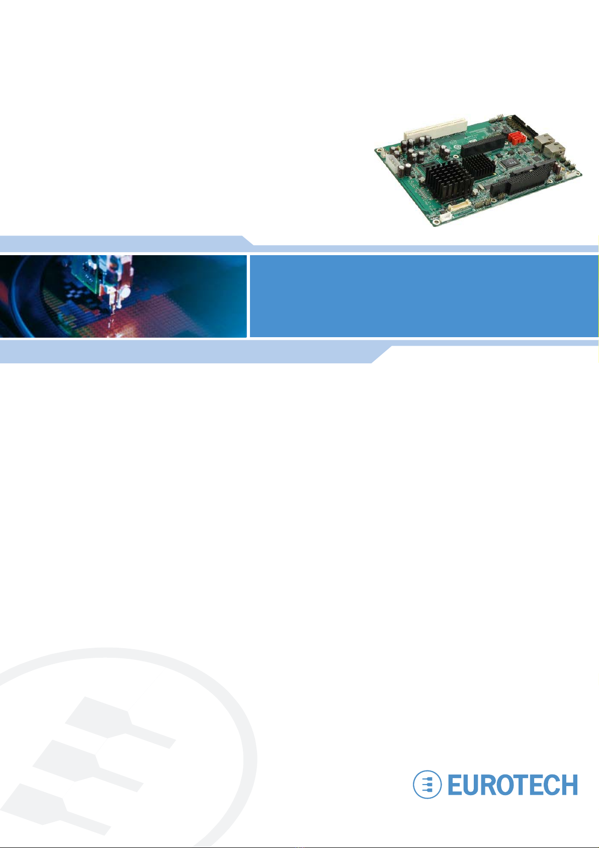
ALUDRA
5.25" Single Board Compute
r

ALUDRA user manual
Life support policy
Eurotech products are not authorized for use as critical components in life support devices or systems without the
express written approval of Eurotech.
Warranty
For Warranty terms and conditions users should contact their local Eurotech Sales Office.
See Eurotech Group Worldwide Presence for full contact details.
Disclaimer
The information in this document is subject to change without notice and should not be construed as a commitment
by any Eurotech company. While reasonable precautions have been taken, Eurotech assumes no responsibility for
any error that may appear in this document.
Trademarks
All trademarks both marked and not marked appearing in this document are the property of their respective owners.
Revision history
Issue no. PCB Date Comments
A
4 November 2009 First full release.
© 2009 Eurotech. All rights reserved.
For contact details, see page 122.

Contents
Issue A 3
Contents
Important user information..............................................................................................................4
Safety notices and warnings ..............................................................................................4
Life support policy ..............................................................................................................6
WEEE.................................................................................................................................6
RoHS .................................................................................................................................6
Introduction.....................................................................................................................................7
ALUDRA ‘at a glance’.........................................................................................................8
Detailed Specifications..................................................................................................................12
Board Dimensions............................................................................................................12
External Interface Panel Dimensions ...............................................................................13
Data Flow .........................................................................................................................13
Embedded ALUDRA Processor........................................................................................14
Intel 945GSE Northbridge Chipset ...................................................................................16
Intel®ICH7-M Southbridge Chipset ..................................................................................19
LPC Bus Components......................................................................................................27
Environmental and Power Specifications .........................................................................29
Unpacking.....................................................................................................................................30
Connectors ...................................................................................................................................31
External Peripheral Interface Connector Panel ................................................................58
Installation.....................................................................................................................................59
Installation Considerations ...............................................................................................59
SO-DIMM and CF Card Installation..................................................................................61
Jumper Settings ...............................................................................................................63
Chassis Installation ..........................................................................................................70
Internal Peripheral Device Connections ...........................................................................71
External Peripheral Interface Connection.........................................................................76
AMI BIOS......................................................................................................................................77
Main .................................................................................................................................79
Advanced .........................................................................................................................80
PCI/PnP .........................................................................................................................101
Boot................................................................................................................................103
Security ..........................................................................................................................105
Chipset ...........................................................................................................................106
Exit ................................................................................................................................. 110
Appendix A - Terminology ........................................................................................................... 111
Appendix B - DIO Interface......................................................................................................... 113
DIO Connector Pinouts .................................................................................................. 113
Assembly Language Samples........................................................................................ 113
Appendix C - Watchdog Timer .................................................................................................... 114
Appendix D - Address Mapping .................................................................................................. 116
I/O Address Map ............................................................................................................ 116
IRQ Address Map........................................................................................................... 118
Memory Address Map .................................................................................................... 119
Appendix E – Cable Kit and Optional Items................................................................................120
Eurotech Group Worldwide Presence.........................................................................................122

ALUDRA user manual
Issue A
4
Important user information
In order to lower the risk of personal injury, electric shock, fire or equipment damage,
users must observe the following precautions as well as good technical judgment,
whenever this product is installed or used.
All reasonable efforts have been made to ensure the accuracy of this document;
however, Eurotech assumes no liability resulting from any error/omission in this
document, or from the use of the information contained herein.
Eurotech reserves the right to revise this document and to change its contents at any
time without obligation to notify any person of such revision or changes.
Safety notices and warnings
The following general safety precautions must be observed during all phases of
operation, service, and repair of this equipment. Failure to comply with these precautions
or with specific warnings elsewhere in this manual violates safety standards of design,
manufacture, and intended use of the equipment. Eurotech assumes no liability for the
customer’s failure to comply with these requirements.
The safety precautions listed below represent warnings of certain dangers of which
Eurotech is aware of. You, as the user of the product, should follow these warnings and
all other safety precautions necessary for the safe operation of the equipment in your
operating environment.
Installation in cupboards and safes
In the event that the product is placed within a cupboard or safe, together with other heat
generating equipment, ensure proper ventilation.
Do not operate in an explosive atmosphere
Do not operate the equipment in the presence of flammable gases or fumes. Operation of
any electrical equipment in such an environment constitutes a definite safety hazard.
Important user information
Issue A 5
Alerts that can be found throughout this manual
The following alerts are used within this manual and indicate potentially dangerous
situations:
Symbol Explanation
Information and/or notes:
These will highlight important features or instructions that should be
observed.
Warning:
Information regarding potential hazards:
Personal injury or death could occur. Also damage to the system,
connected peripheral devices, or software could occur if the warnings
are not carefully followed.
Appropriate safety precautions should always be used, these should
meet the requirements set out for the environment that the equipment
will be deployed in.
Danger, electrical shock hazard:
Information regarding potential electrical shock hazards:
Personal injury or death could occur. Also damage to the system,
connected peripheral devices, or software could occur if the warnings
are not carefully followed.
Appropriate safety precautions should always be used, these should
meet the requirements set out for the environment that the equipment
will be deployed in.
Battery
The board contains a lithium non-rechargeable battery. Do not short circuit the battery or
place on a metal surface where the battery terminals could be shorted. When disposing
of the board or battery, take appropriate care. Do not incinerate, crush or otherwise
damage the battery. Use only standard CR1220 button batteries.
Antistatic precautions
To avoid damage caused by ESD (Electro Static Discharge), always use appropriate
antistatic precautions when handing any electronic equipment.
Packaging
Please ensure that, should a board need to be returned to Eurotech, it is adequately
packed, preferably in the original packing material.
Electromagnetic compatibility (EMC)
The ALUDRA is classified as a component with regard to the European Community EMC
regulations and it is the user’s responsibility to ensure that systems using the board are
compliant with the appropriate EMC standards.

ALUDRA user manual
Issue A
6
Life support policy
Eurotech products are not authorized for use as critical components in life support
devices or systems without the express written approval of Eurotech.
WEEE
The information below is issued in compliance with the regulations as set out in the
2002/96/EC directive, subsequently superseded by 2003/108/EC. It refers electrical and
electronic equipment and the waste management of such products.
When disposing of a device, including all of its components, subassemblies and materials
that are an integral part of the product, you should consider the WEEE directive.
The symbol to the right has been attached to the equipment or, if this has not
been possible, on the packaging, instruction literature and/or the guarantee
sheet. By using this symbol, it states that the device has been marketed after
August 13th 2005, and implies that you must separate all of its components
when possible, and dispose of them in accordance with local waste disposal
legislations:
Because of the substances present in the equipment, improper use or disposal of the
refuse can cause damage to human health and to the environment.
With reference to WEEE, it is compulsory not dispose of the equipment with normal
urban refuse, arrangements should be instigated for separate collection and disposal.
Contact your local waste collection body for more detailed recycling information.
In case of illicit disposal, sanctions will be levied on transgressors.
RoHS
This device, including all it components, subassemblies and the consumable materials
that are an integral part of the product, has been manufactured in compliance with the
European directive 2002/95/EC known as the RoHS directive (Restrictions on the use of
certain Hazardous Substances). This directive targets the reduction of certain hazardous
substances previously used in electrical and electronic equipment (EEE).
Introduction
Issue A 7
Introduction
The ALUDRA 5.25" motherboard utilises a 45nm Intel®Atom™ N270 processor with a
1.60 GHz clock, a 533 MHz FSB and a 512 KB L2 cache. The ALUDRA also supports
one 200-pin 533MHz 2.0GB (max.) DDR2 SDRAM SO-DIMM. The board comes with one
LVDS connector and supports 18-bit dual-channel LVDS screens. The ALUDRA also
comes with one PCI socket, two PCI Express (PCIe) sockets, a PC/104-Plus expansion
slot and two Gigabit Ethernet (GbE) connectors.
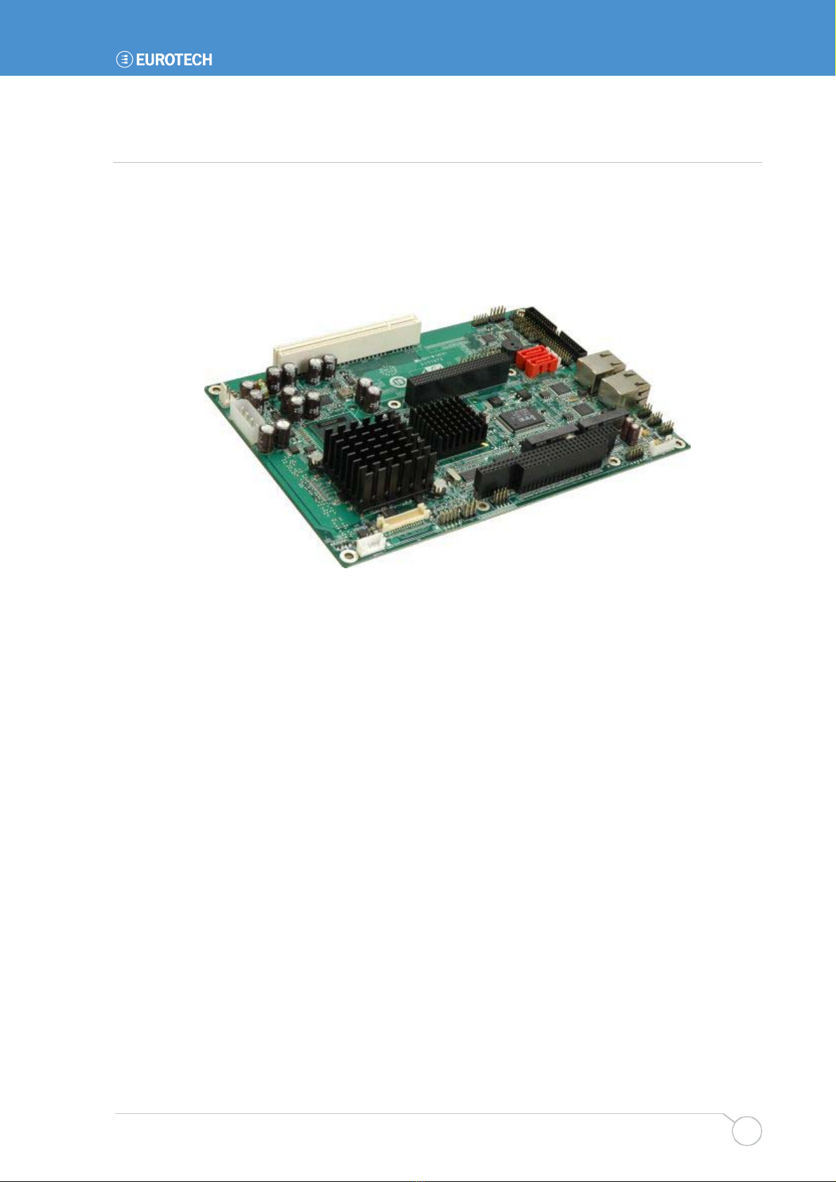
Figure 1: ALUDRA


Introduction
Issue A 9
ALUDRA Peripheral Connectors and Jumpers
The ALUDRA has the following connectors on-board:
One ATX power connector for +5V and +12V supplies
One Audio connector
One ATX power control connector
One Backlight inverter connector
One CompactFlash®socket
One CRT connector
One Digital input/output (DIO) connector
One Fan connector
One Front panel connector
One IDE disk drive connectors (44-pin)
One Infrared interface (IrDA) connector
One Keyboard/mouse connector
One LVDS connector
One Parallel port connector
One PC/104-Plus slot
One PCI slot
Two PCIe Mini Card slots
Two Gigabit Ethernet (GbE) connectors
Two Serial ATA (SATA) drive connectors
One SDVO connector
Three RS-232 serial port connectors
One RS-232/422/485 serial port connector
One TPM connector
One TV Out connector
Three USB 2.0 connectors (supports six USB 2.0 devices)
The ALUDRA has the following on-board jumpers:
AT power selection
Clear CMOS
CF card setup
LVDS Voltage Selection
LVDS Panel Resolution Selection
ALUDRA user manual
Issue A
10
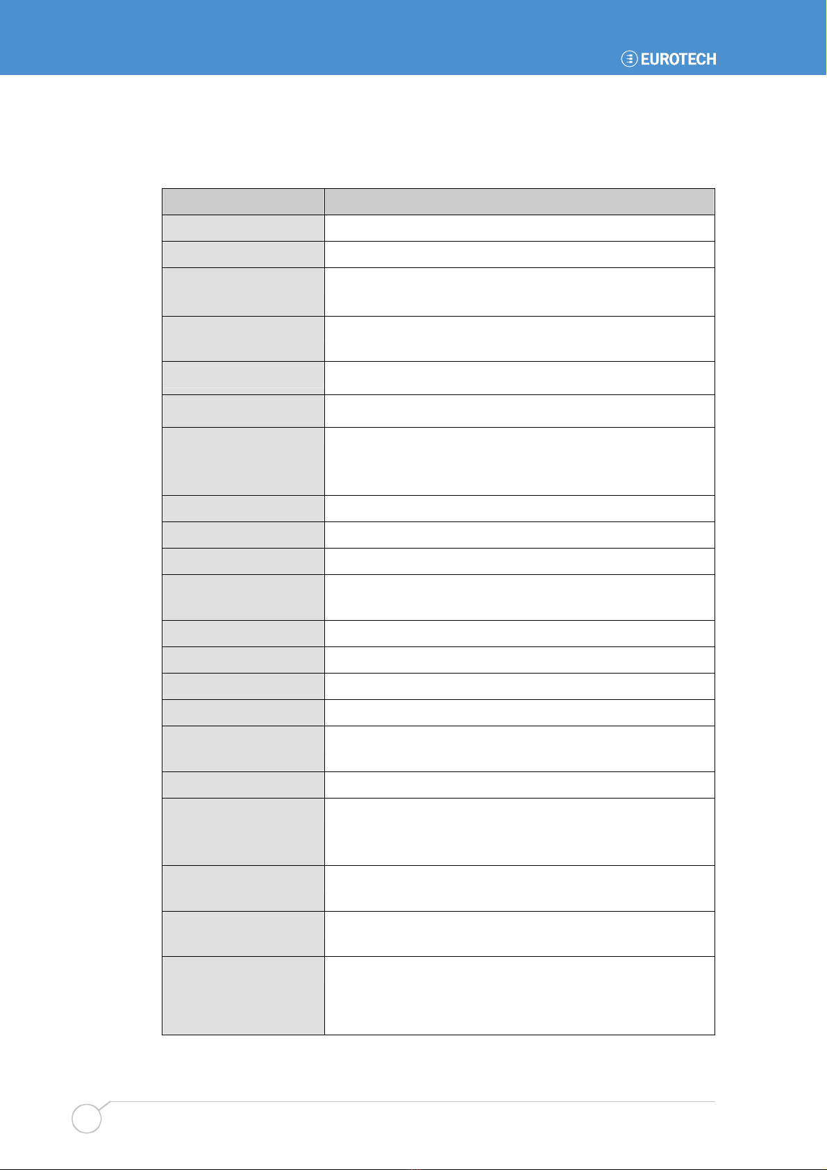
Technical Specifications
ALUDRA technical specifications are listed in Table 1.
Specification ALUDRA
System CPU 45 nm 1.6 GHz Intel®Atom™ N270
Front Side Bus (FSB) 533 MHz
System Chipset Northbridge: Intel®945GSE
Southbridge: Intel®ICH7-M
Memory One 200-pin SO-DIMM socket supports one 533/400 MHz
2.0 GB (max.) DDR2 SDRAM SO-DIMM
CompactFlash®One CompactFlash®Type II socket
Super I/O ITE IT8718F
Display Analog CRT supports CRT hot-plug
HDTV with 1080i maximum resolution supported
18-bit dual-channel LVDS integrated in Intel®945GSE
BIOS AMI BIOS label
Audio Realtek ALC655 AC'97 codec
LAN Two Realtek RTL8111CP GbE controllers
COM Three RS-232 serial ports
One RS-232/422/485 serial port
USB2.0 Six USB 2.0 devices supported by on-board pin-headers
SATA Two 1.5 Gbps SATA drives supported
Keyboard/mouse One 6-pin header for keyboard and mouse
Parallel Port One 26-pin parallel port connector
Hard Drives One 44-pin IDE connector connects to two Ultra
ATA33/66/100 devices
TPM One 20-pin header support TPM function
Expansion One PC/104-Plus expansion slot (ISA + PCI bus)
Two PCIe mini card (PCIe bus)
One PCI slot (PCI bus)
Digital I/O One 8-bit digital input/output connector; 4-bit input/4-bit
output through the ITE IT8718F super I/O
Watchdog Timer Software programmable 1-255 sec. through the ITE super
I/O
Infrared One infrared connector through the ITE super I/O. Supports:
Serial Infrared (SIR)
Amplitude Shift Keyed IR (ASKIR)
Introduction
Issue A 11
Power Supply ATX and AT power supported
with one 1 GB DDR2 SO-DIMM)
Temperature 0ºC – 60ºC (32ºF - 140ºF)
Humidity (operating) 5%~95% non-condensing
Dimensions (LxW) 203 mm x 146 mm
Weight (GW/NW) 1000g/400g
Table 1: Technical Specifications

ALUDRA user manual
Issue A
12
Detailed Specifications
Board Dimensions
The dimensions of the board are listed below:
Length: 203 mm
Width: 146 mm
Figure 4: ALUDRA Dimensions (mm)

Detailed Specifications
Issue A 13
External Interface Panel Dimensions
External peripheral interface connector panel dimensions are shown in Figure 5.
Figure 5: External Interface Panel Dimensions (mm)
Data Flow
Figure 6 shows the data flow between the two on-board chipsets and other components
installed on the motherboard and described in the following sections of this chapter.
Figure 6: Data Flow Block Diagram

ALUDRA user manual
Issue A
14
Embedded ALUDRA Processor
The ALUDRA comes with an embedded 45 nm 1.60 GHz Intel®Atom™ processor N270.
The processor supports a 533 MHz FSB and has a 1.6 GHz 512 KB L2 cache. The low
power processor has a maximum power of 2.5 W. The processor is shown in Figure 7
below.
Figure 7: Embedded Processor
Features
Some of the features of the Intel®Atom™ processor N270 are listed below:
On-die, primary 32-kB instructions cache and 24-kB write-back data cache
533-MHz source-synchronous front side bus (FSB)
2-Threads support
On-die 512-kB, 8-way L2 cache
Support for IA 32-bit architecture
Intel®Streaming SIMD Extensions-2 and -3 (Intel®SSE2 and Intel®SSE3) support
and Supplemental Streaming SIMD Extension 3 (SSSE3) support
Micro-FCBGA8 packaging technologies
Thermal management support via Intel®Thermal Monitor 1 and Intel Thermal Monitor 2
FSB Lane Reversal for flexible routing
Supports C0/C1(e)/C2(e)/C4(e)
L2 Dynamic Cache Sizing
Advanced power management features including Enhanced Intel SpeedStep®
Technology
Execute Disable Bit support for enhanced security

ALUDRA user manual
Issue A
16
Intel 945GSE Northbridge Chipset
The Intel®945GSE Graphics and Memory Controller Hub (GMCH) supports the
embedded Intel®Atom™ N270 processor. The Intel®945GSE is interfaced to the
processor through a 533 MHz FSB.
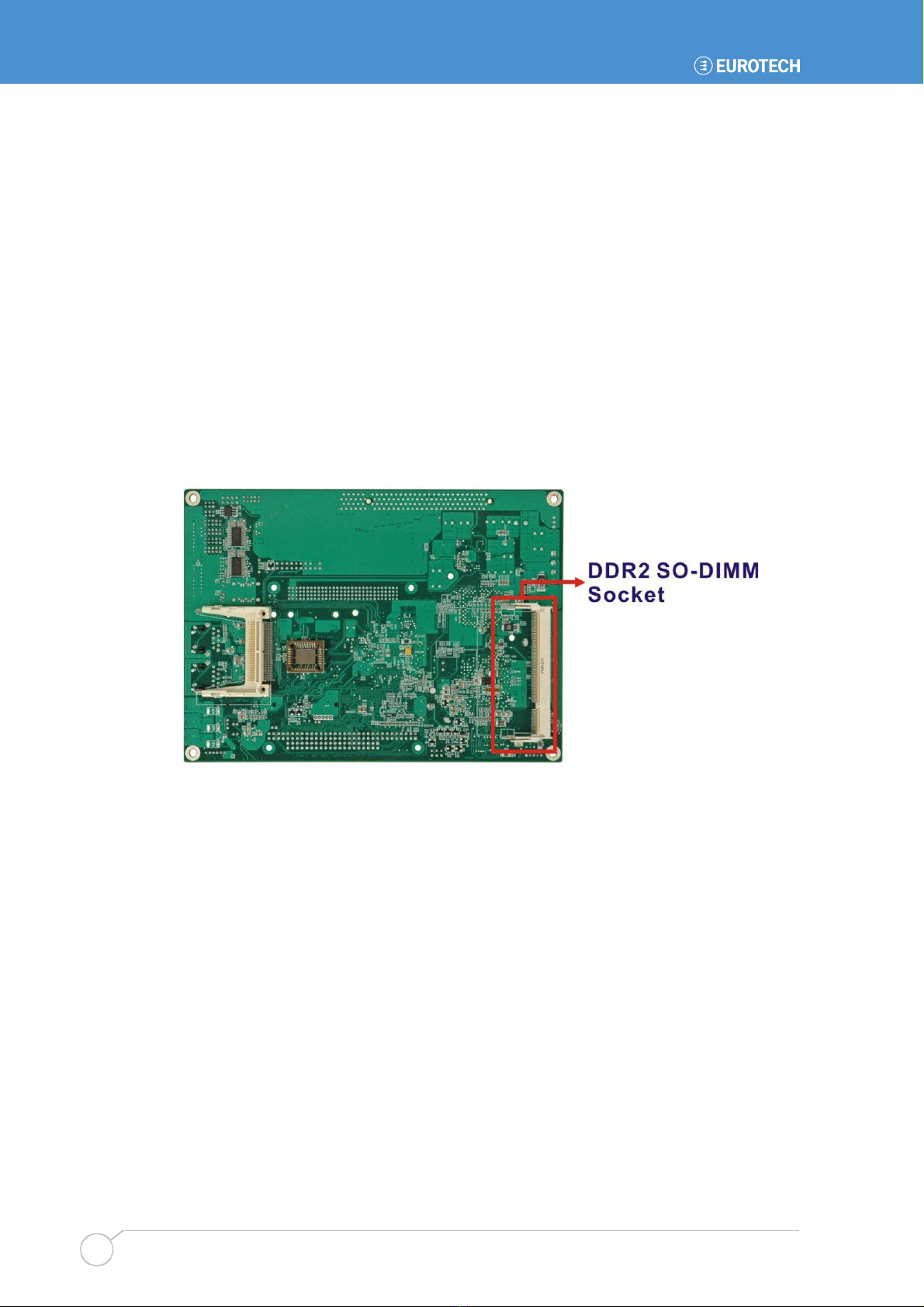
Intel®945GSE DDR2 Controller
There is one 200-pin DDR2 SO-DIMM socket on the ALUDRA. The socket supports
DDR2 SO-DIMM with the following specifications:
Maximum Memory supported 2 GB
Support for DDR2 at 400 MHz and 533 MHz
No support for Dual-Channel Interleaved mode of operation
Enhanced Addressing support (Swap only)
The SO-DIMM socket is shown in Figure 9 below.
Figure 9: DDR2 SO-DIMM Socket
Intel®945GSE Graphics
The Intel®945GSE supports CRT, LVDS, TV-Out and SDVO. The internal graphics
engine has the following features:
Intel®Gen 3.5 Integrated Graphics Engine
250-MHz core render clock and 200 MHz core display clock at 1.05-V core voltage
Supports TV-Out, LVDS, CRT and SDVO
Dynamic Video Memory Technology (DVMT 3.0)
Intel®Display Power Saving Technology 2.0 (Intel®DPST 2.0)
Intel®Smart 2D Display Technology (Intel®S2DDT)
Intel®Automatic Display Brightness
Video Capture via x1 concurrent PCIe port
Concurrent operation of x1 PCIe and SDVO
Four pixel rate HWMC

Detailed Specifications
Issue A 17
Microsoft DirectX* 9.1 operating system
Intermediate Z in Classic Rendering
Internal Graphics Display Device States: D0, D1, D3
Graphics Display Adapter States: D0, D3.
Figure 10: CRT, LVDS and TV-Out Connectors
Analogue CRT Graphics Mode
The analogue CRT bus is interfaced to an on-board 10-pin connector. The connector is
shown in Figure 10. The CRT interface has the following features.
Integrated 400-MHz RAMDAC
Analogue Monitor Support up to QXGA
Support for CRT Hot Plug
LVDS Interface
The LVDS interface is connected directly to the LVDS connector on the board (Figure
10). The LVDS interface has the following features.
Panel support up to UXGA (1600 x 1200)
25-MHz to 112-MHz single-/dual-channel; @18 bpp
- TFT panel type supported
Pixel Dithering for 18-bit TFT panel to emulate 24-bpp true colour displays
Panel Fitting. Panning, and Center Mode Supported
CPIS 1.5 compliant
Spread spectrum clocking supported
Panel Power Sequencing support
Integrated PWM interface for LCD backlight inverter control


Detailed Specifications
Issue A 19
Intel®ICH7-M Southbridge Chipset
The Intel®ICH7-M chipset is connected to the Intel®945GSE GMCH through the chip-to-
chip Direct Media Interface (DMI). Some of the features of the Intel®ICH7-M are listed
below.
Complies with PCI Express Base Specification, Revision 1.0a
Complies with PCI Local Bus Specification, Revision 2.3 and supports 33MHz PCI
operations
Supports ACPI Power Management Logic
Contains:
- Enhanced DMA controller
- Interrupt controller
- Timer functions
Integrated SATA host controller with DMA operations interfaced to two SATA
connectors on the ALUDRA
Supports the four USB 2.0 devices on the ALUDRA with four UHCI controllers and
one EHCI controller
Complies with System Management Bus (SMBus) Specification, Version 2.0
Supports Audio Codec ’97 (AC’97) Revision 2.3
Supports Intel®High Definition Audio
Contains Low Pin Count (LPC) interface
Supports Firmware Hub (FWH) interface
Serial peripheral interface support

ALUDRA user manual
Issue A
20
Intel®ICH7-M Audio Codec ’97 Controller
The Audio Codec ’97 (AC’97) controller integrated into the ICH7-M complies with AC’97
Component Specification, Version 2.3. The AC’97 controller is integrated to a RealTek
ALC655 audio codec. The RealTek ALC655 is in turn connected to on-board audio
connectors, which are then connected to compliant audio devices. The RealTek ALC655
is a 16-bit, full-duplex AC'97 Rev. 2.3 compatible six-channel audio codec. The codec
and the audio connectors are shown in Figure 11.
Figure 11: Audio Codec and Connectors
Some of the features of the RealTek ALC655 are listed below:
Meets performance requirements for audio on PC99/2001 systems
Meets Microsoft WHQL/WLP 2.0 audio requirements
16-bit Stereo full-duplex CODEC with 48KHz sampling rate
Compliant with AC'97 Rev 2.3 specifications
- Front-Out, Surround-Out, MIC-In and LINE-In Jack Sensing
- 14.318MHz -> 24.576MHz PLL to eliminate crystal
- 12.288MHz BITCLK input
- Integrated PCBEEP generator to save buzzer
- Interrupt capability
Three analogue line-level stereo inputs with 5-bit volume control, LINE_IN, CD, AUX
High-quality differential CD input
Two analogue line-level mono inputs: PCBEEP, PHONE-IN
Two software selectable MIC inputs
Dedicated Front-MIC input for front panel applications (software selectable)
Boost preamplifier for MIC input
Table of contents
Other Eurotech Motherboard manuals

Eurotech
Eurotech AIM104-COM8 User manual

Eurotech
Eurotech Bitsy G5 User manual

Eurotech
Eurotech ANTARES User manual

Eurotech
Eurotech Vector User manual

Eurotech
Eurotech Titan User manual

Eurotech
Eurotech VIPER User manual

Eurotech
Eurotech ZEUS User manual

Eurotech
Eurotech GEMINI User manual

Eurotech
Eurotech Apollo User manual

Eurotech
Eurotech PXA320 User manual


