4
6. Do not operate machine while under the influence of
alcohol or drugs.
7. Muffler and engine become hot and can cause a burn. Do
not touch.
8. Exercise extreme caution when operating on or crossing
gravel surfaces. Stay alert for hidden hazards or traffic.
9. Exercise caution when changing direction and while
operating on slopes.
10. Plan your snow throwing pattern to avoid discharge
towards windows, walls, cars etc. To avoid property
damage or personal injury caused by a ricochet.
11. Never direct discharge at children, bystanders and pets
or allow anyone in front of the machine.
12. Do not overload machine capacity by attempting to clear
snow at too fast of a rate.
13. Neveroperatethis machine withoutgoodvisibility or light.
Always be sure of your footing and keep a firm hold on
the handles. Walk, never run.
14. Disengage power to the auger/impeller when
transporting or not in use.
15. Never operate machine at high transport speeds on
slippery surfaces. Look down and behind and use care
when in reverse.
16. If the machine should start to vibrate abnormally, stop the
engine, disconnect the spark plug and ground it against
the engine. Inspect thoroughly for damage. Repair any
damage before starting and operating.
17. Disengage the control handle and stop engine before you
leave the operating position (behind the handles). Wait
until the auger comes to a complete stop before
unclogging the discharge chute, making any
adjustments, or inspections.
18. Never put your hand in the discharge or collector
openings. Always use a clearing tool to unclog the
discharge opening.
19. Use only attachments and accessories approved by the
manufacturer.
20. If situations occur which are not covered in this manual,
use care and good judgment. Call customer assistance
for the name of your nearest servicing dealer.
Maintenance And Storage
1. Never tamper with safety devices. Check their proper
operation regularly.
2. Disengage the control handle and stop engine. Wait until
the auger/impeller come to a complete stop. Disconnect
the spark plug wire and ground against the engine to
prevent unintended starting before cleaning, repairing, or
inspecting.
3. Check bolts, and screws for proper tightness at frequent
intervals to keep the machine in safe working condition.
Also, visually inspect machine for any damage.
4. Do not change the engine governor setting or over-speed
the engine. The governor controls the maximum safe
operating speed of the engine.
5. Snow thrower shave plates and skid shoes are subject to
wear and damage. For your safety protection, frequently
check all components and replace with original
equipment manufacturer’s (O.E.M.) parts only. “Use of
parts which do not meet the original equipment
specifications may lead to improper performance and
compromise safety!”
6. Check controls periodically to verify they engage and
disengage properly and adjust, if necessary. Refer to the
adjustment section in this operator’s manual for
instructions.
7. Maintain or replace safety and instruction labels, as
necessary.
8. Observe proper disposal laws andregulations forgas, oil,
etc. to protect the environment.
9. Prior to storing, run machine a few minutes to clear snow
from machine and prevent freeze up of auger/impeller.
10. Never store the machine or fuel container inside where
there is an open flame, spark or pilot light such as a water
heater, furnace, clothes dryer etc.
11. Always refer to the operator’s manual for proper
instructions on off-season storage.
Your Responsibility:
• Restrict the use of this power machine to persons who
read, understand and follow the warnings and
instructions in this manual and on the machine.
• FUEL MIXTURE 50:1 OR 2%
• MIX QUALITY 2 CYCLE OIL (TC-W11 OR TC-W3) WITH COLD WEATHER
GAS IN GAS CAN ONLY
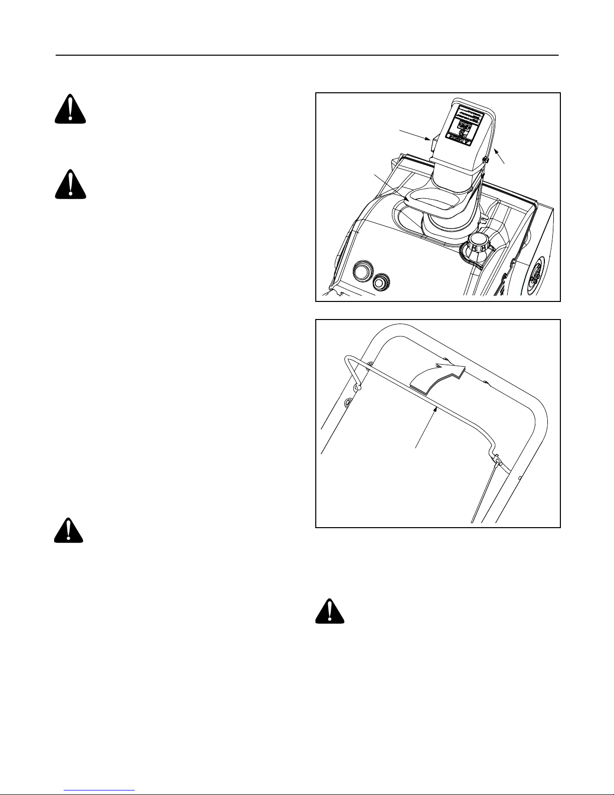
1.)
INSERT IGNITION KEY, TURN TO RUN POSITION.
2.)
MOVE CHOKE LEVER TO FULL (ON) POSITION. PUSH PRIMER BUTTON 3x.
3.)
ROPE START: PULL SLOWLY UNTIL HARDER TO PULL, THEN PULL RAPIDLY TO START.
REPEAT PRIMING IF NEEDED.
ELECTRIC START: DO NOT USE IN RAIN. CONNECT POWER CORD AND PUSH STARTER
BUTTON. REPEAT PRIMING IF NEEDED.
4.) MOVE CHOKE SLOWLY TO OFF POSITION.
5.) TO STOP ENGINE: TURN KEY TO STOP POSITION.
RUN
PREPARATIONS AND STARTING INSTRUCTIONS:
AVANT LE DÉMARRAGE ET MISE EN MARCHE DU MOTEUR:
• MÉLANGE DE CARBURANT À UN TAUX DE 50 À 1 OU 2%.
• MÉLANGE UNE HUILE DE QUALITÉ POUR MOTEURS À DEUX TEMPS
(TC-W11 OR TC-W3) AVEC UNE ESSENCE PRÉPARÉE POUR TEMPS FROID.
1.) ENFONCEZ LA CLÉ DE CONTACT. TOURNEZ LA CLÉ À LA POSITION «RUN».
2.) PLACEZ LA MANETTE DU VOLET DE DÉPART À LA POSITION VOLET FERMÉ «ON».
ENFONCEZ TROIS FOIS LE BOUTON D'AMORÇAGE.
3.) DÉMARREUR À LANCEUR: TIREZ LA CORDE LENTEMENT JUSQU'À CE QUE VOUS SENTIEZ UNE
LÉGÈRE RÉSISTANCE, PUIS TIREZ RAPIDEMENT POUR DÉMARRER. RÉPÉTEZ L'AMORÇAGE AU BESOIN.
DÉMARREUR ÉLECTRIQUE: N'EMPLOYEZ PAS DANS LA PLUIE. BRANCHEZ LE FIL ÉLECTRIQUE
ET APPUYEZ SUR LE BOUTON DU DÉMARREUR. RÉPÉTEZ L'AMORÇAGE AU BESOIN.
4.) OUVREZ LENTEMENT LE VOLET DE DÉPART.
5.) POUR ARRÊTEZ LE MOTEUR: TOUREZ LA CLÉ
À LA POSITION «STOP».
BOUTON D'AMORÇAGE
PRIMER BUTTON
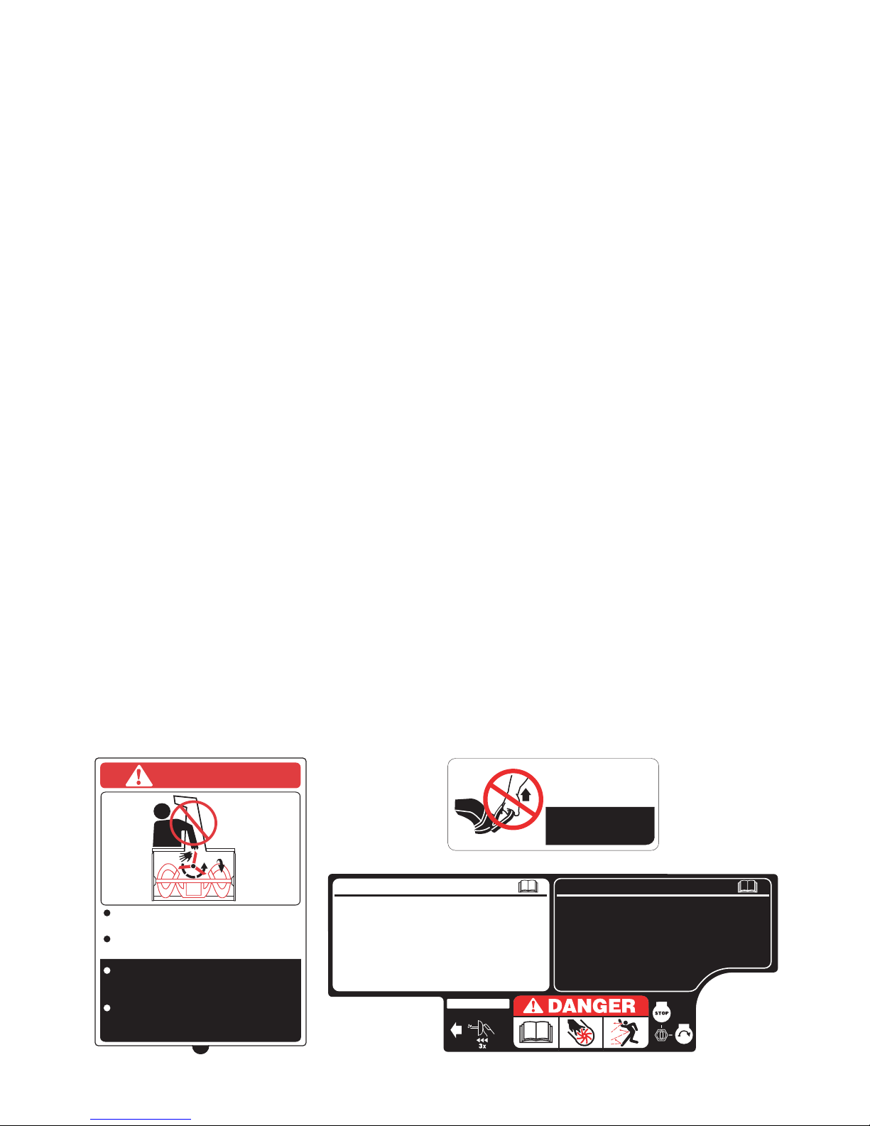
DANGER
NEVER PUT HAND IN CHUTE. CAN
AMPUTATE
HANDS AND FINGERS.
STOP ENGINE AND AUGER BEFORE USING
CLEAN-OUT TOOL OR STICK.
ARRÊTEZ LE MOTEUR ET LA TARIÈRE AVANT
D'UTILISER L'OUTIL DE DÉGAGEMENT
DE LA GOULOTTE OU UN BÂTON.
NE PLACEZ JAMAIS VOS MAINS DANS LA
GOULOTTE. LES PIÈCES EN MOUVEMENT
PEUVENT AMPUTER MAINS ET DOIGTS.
FOR TURNING,
NOT LIFTING
POUR TOURNER,
PAS POUR LE LEVAGE