Mulch Master SYJ-1000 User manual


Table of Contents
Know Your Electric Leaf Eater …………………………………………….........2
Assembly …………………………………..……………………………….…….3-6
Safety Rules and Precautions ……………………………..……………........7-8
Electrical Requirements ……………………………………………….......…. 8-9
Motor Information ……………………………………...………………...………10
Safe Operating Instructions ……………………………………………......10-12
1. Moving Your Unit …………………………………………………………..11
2. Loading Your Unit ……………………………………………….…...........11
3. Mulching Control Lever ……………………………………….…........11-12
4. Circuit Breaker/Reset ……………………………………...……...……….12
Maintenance …………………...…………………………..……....………....13-14
1. Cleaning ………………………………………………………….…....…...13
2. Remove/Replace Cutting Line ……………………………………..…….13
3. Remove/Clean Air Filter ……………………………………..….….….…14
Trouble Shooting ………………………………….……………………………..14
Part List …………………………………………………………………………....16
Figure 1
1

KNOW YOUR ELECTRIC LEAF EATER
A. Introduction
Your Electric Leaf-Eater is a quality built product that is designed to provide you with a unit
that is not only affordable, but will perform with a minimum of care and maintenance.
Special Features Include:
* Powerful universal electric motor
* Runs on normal household current
* Easily moved from place to place
* Easily replaceable cutting cords with extras supplied with each unit.
B. Unpacking Instructions
Your unit has been carefully packed at the factory to prevent damage during shipment and
storage.
Carefully unpack the carton as follows:
1. Remove contents from carton
2. Check parts against list shown
3. Examine for damage
Carton Contents
Key # Description Qty.
1 Funnel (half) 2
2 Upper Housing 1
3 Lower Housing Assembly 1
4 Support 2
5 Shaft 1
6 Wheel 2
7 Handle 1
8 Owner’s Manual 1
9 Hardware Package 1
10 Cutting Lines 10
FIGURE 2
2

ASSEMBLY
A. Preparation
Your owner’s manual has been developed to help you assemble the unit and to
understand its safe operation. It is important that you read your manual completely to
become familiar with the unit before you begin assembly.
a. Read your owner’s manual carefully
b. Refer to following Tools and Hardware we have been offered
1. Assembling Supports and Wheels
To install the two supports and two wheels, align the shaft, thimbles and wheels with the
holes in the two supports. Fasten the wheels with the M6 self-locking hex nuts as shown in
Figure 3.
CAUTION: Don’t fasten the nut too tight to make sure the wheels can be easily
running.
3

FIGURE 3
2. Assemble Supports and Lower Housing Assembly
Align the holes in the two supports with the holes in the lower housing, fasten the supports
and lower housing assembly with stud plate A and M5 self-locking hex nuts as shown in
Figure 4.
FIGURE 4
4

3. Assemble the Handle
Align the holes in the handle with the holes in the upper housing, and fasten the handle
and upper housing with stud plate B and M5 self-locking hex nuts as shown in Figure 5.
FIGURE 5
4. Assemble Upper and Lower Housing
The three Tinnerman Clips were on the edge of the Lower Housing in areas provided.
Place both Upper Housing and Lower Housing upside down and align the slot in the edge
of the Upper Housing with the tab on the Lower Housing. Push the Upper Housing down
until it is seated firmly in the Lower Housing. Position the assembly in the upright position
and fasten both housings together using the three M5×10,Pan Head Screws as shown in
Figure 6.
FIGURE 6
5

5. Assemble Funnel
Assemble funnel with M5×10,Pan Head Screws, Plates and M5 self-locking hex nuts.
Place screw heads on inside with plates and nuts on outside as shown in Figure 7.
FIGURE 7
6. Attach Funnel to Upper Housing
Align six holes in Funnel with six Holes in Upper Housing, and fasten securely using six
ST4.2×10, Sht.Mtl., screws and #5 flat washers. Then assembly complete, as shown in
figure 8.
FIGURE 8
6

SAFETY RULES AND PRECAUTIONS
Warning: To reduce the risk of fire, electric shock, and personal injury, the
following basic safety precautions should always be followed.
READ ALL INSTRUCTIONS
1. Become familiar with all sections of owner’s manual before attempting to operate the
shredder. This shredder should be used solely for the purpose it was intended.
2. Use only parts or accessories specifically designed for use with this shredder. Using
other parts or accessories could increase risk of injury.
3. Keep Children Away-all visitors should be kept at a distance from the work area.
4. Never allow your hands or any part of your body or clothing inside the upper housing
area.
5. Avoid Dangerous Environments-do not use shredder in damp or wet locations. Do
not operate or store shredder in wet areas. Do not operate in rain. Store indoors when
not in use, in a dry, and high or locked-up place-out of reach of children.
6. This shredder should be operated on a solid, level surface.
7. Dress Properly-do not wear loose clothing or jewelry. They can be caught in moving
parts. Use of work gloves and substantial footwear is advised when working outdoors.
Wear protective hair covering to contain long hair.
8. Stay Alert-Watch what you doing. Use common sense. Do not operate shredder
when you are tires.
9. Do not Abuse Power or Extension Cords-Never carry unit by its power cord or yank
cord to disconnect from receptacle. Keep all cords clean and away form heat, oil and
sharp edges and inspect for damage before each use.
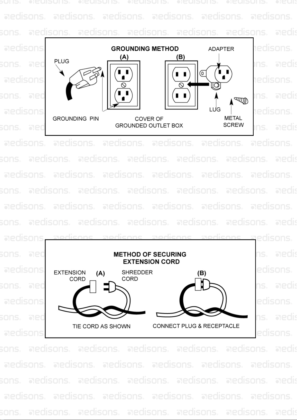
10. Ground unit properly. Follow instructions on page 9 when connecting to electrical
outlet.
11. Warning-To reduce the risk of electrical shock, use only an extension cord intended
for outdoor use. See page 9 for additional information on extension cords.
12. Ground fault circuit interrupter (GFCI) protection should be provided on the circuit(s)
or outlet(s) to be used for this shredder. Receptacles are available having built-in
GFCI protection and may be used for this measure of safety.
13. If it is necessary for any reason to inspect, clean or repair the shredder, turn the
shredder off and wait until it comes to a complete stop, then disconnect the power
cord before attempting such inspection or repair.
14. Disconnect shredder from the power source when not in use, before servicing, and
when changing cutting lines.
15. When feeding material into the shredder be extremely careful that pieces of metal,
rocks, bottles, cans or other foreign objects are not included.
16. Do not force the shredder. It will do the job better and with less likelihood of risk of
injury when used at the rate for which it was designed.
17. If the cutting mechanism strikes a foreign object or if your shredder should start
making an unusual noise or vibration, immediately switch it off, wait until the shredder
has come to a complete stop, then disconnect the power cord and take the following
7

steps:
A. Remove any foreign or clogged material.
B. Check for any loose parts and tighten to assure continued safe operation.
C. Replace or repair any damaged parts.
18. Avoid unintentional starting. Be sure switch is off when plugging in the shredder.
19. Always use safety glasses and face or dust mask if operation is dusty.
20. Check discharge area periodically after stopping shredder to assure the processed
material does not build up and clog motor cooling vents.
21. Do Not Overreach-keep proper footing and balance at all times.
22. Do not move shredder when motor is running or with finger n the switch.
23. Maintain Shredder with Care-Follow instructions for replacing cutting lines and for
cleaning air filter. Inspect shredder power cord periodically, and if damaged, have it
repaired by an authorized service facility. Keep handles dry, clean and free from oil
and grease.
24. Check Damaged Parts-Before further use of the shredder, any part that is damaged
should be carefully checked to determine that it will operate properly and perform its
intended function. Check for alignment of moving parts, mounting, and any other
condition that may affect its operation. Aguard or other part that is damaged should be
properly repaired or replaced by an authorized service center unless indicated
elsewhere in this manual.
SAVE THESE INSTRUCTIONS
ELECTRICAL REQUIREMENTS
Important: Use a 14 ga. Or heavier extension cord with a maximum length of
100ft.
Grounding Instructions
This shredder should be grounded while in use to reduce the risk of electric shock to the
operator.
The shredder is equipped with a three-conductor cord and three-prong grounding plug.
The green or green and yellow conductor in the cord is the grounding wire. Never connect
the green or green and yellow wire to a live terminal.
The shredder is intended for use on a circuit that has a grounded outlet box that looks
like the one illustrated in figure 9, sketch A.
An adapter which looks like the adapter illustrated in figure 9, sketch B is available for
connecting three-prong plugs to two-prong receptacles. The green colored rigid ear, lug,
or the like on the adapter, must be connected to a permanent ground, such as a properly
grounded outlet box, using a metal screw.
Check with a qualified electrician or serviceman if the grounding instructions are not
completely understood, or if in doubt as to whether the shredder is properly grounded.
8

Figure 9
Extensions Cords
Only use three-wire extension cords that have three-prong grounding plugs and
three-hole receptacles that accept the shredder’s plug. When using an extension cord,
make sure that it is in good condition.
Use a 14 ga, or heavier extension cord with a maximum length of 100 ft. An undersized
extension cord will cause a drop in line voltage resulting in loss of power and overheating.
Warning-To reduce the risk of electric shock, only use extension cords intended for
outdoor use, such as cord types SW-A, SOW-A, STW-A, STOW-A, SJW-A, SJOW-A,
SJTW-A or SJTOW-A.
To prevent disconnection of the shredder cord from the extension cord during operation,
make a knot as shown in figure 10. Devices for retaining extension cords are also
available at your local hardware retailer.
FIGURE 10
9

MOTOR INFORMATION
1. On/Off Switch
Then On/Off switch is located on the left side of the Lower Housing. To turn unit on lift
switch to “ON” position, see figure 11. To turn unit off push switch down to “OFF” position,
see figure 11.
2. Circuit Breaker/Reset Button
The circuit breaker/reset button is located on the lower, outside front of the motor housing
as shown in figure 11. The unit is designed to shut down in the event of an overload. To
restart, place on/off switch in “OFF” position, push reset button, wait approximately 3
minutes and the place switch in “ON” position.
FIGURE 11
3. Automatic-Restart Thermic Circuit Breaker
Inside the motor there is an automatic reset circuit breaker which will automatically shut
off the circuit in case of unexpected situation, such as the temperature of motor is up to
130℃high, so as to prevent the motor from overload. The circuit will automatically restart
after few minutes.
SAFE OPERATING INSTRUCTIONS
Your Electric Leaf-Eater can be hazardous if improperly or carelessly used.
The instructions and figures shown below demonstrate the right way to use your machine.
Read and understand the operating instructions before you operate your machine. Always
use safe and cautious operating methods.
Please remember the operating and safety instructions have been written for your use.
Failure to read all instructions may result in injury.
Be sure you have read “Rules for Safe Operation” before proceeding.
CAUTION
Disconnect power cord from extension cord before
moving machine from one location to another location.
10

1. Moving Your Unit
Disconnect the power cord from the extension cord or power source, grasp the Handle of
the unit on the Upper Housing, and move to everywhere you choose.
CAUTION
Wear Safety Glasses when operating this machine.
2. Loading Your Machine
With the machine running, feed double handfuls of dry leaves, or single handfuls of wet
leaves, into the hopper. Allow the machine to shred the load completely and regain speed
before reinserting the next load. Do not overload the machine by letting it labor at low
speed: this will cause the circuit breaker to shut the motor off. If this happens, turn the
switch off, unplug the machine, clear the unshredded material from the hopper, reset the
breaker and continue with your shredding.
FIGURE 12
3. Mulching Control Lever
The Control Lever, see figure 13, controls the particle size and speed at which material
goes through the unit. With the Control Lever in the Coarse position, material will process
through the unit faster but will give you a larger particle size than if the lever were in the
Fine position. The Fine position setting will discharge material slower but will give the
smallest particle size.
CAUTION
Do not operate your machine
without the
funnel attached.
Fine: 30-1 Medium: 15-1 Coarse: 8-1
11

FIGURE 13
4. Circuit Breaker
This machine is equipped with a circuit breaker that is designed to shut off the machine in
the event of an overload. To restart your machine after the circuit breaker activates, place
On/Off switch to the “Off” position, push in on the Reset Button, figure 14, and wait for
approximately three minutes. After three minutes place the On/Off switch to the “On”
position and continue to operate.
FIGURE 14
Do not allow shredder material in trash container or leaf
bag to reach bottom of
motor housing. A reduction in
airflow will result and may cause permanent damage to
your motor.
12

MAINTENANCE
CAUTION
Disconnect power cord from power source before
attempting any maintenance.
1. Cleaning Your Unit
Your unit requires a minimum of maintenance other than cleaning. It is recommended that
you clean out built-up residue from inside the Housing area, and from between Mulching
Discs during and after each use. Also tighten all nuts, bolts and screws periodically.
Replace cutting line as often as necessary, see below, and clean Air Filter frequently, see
figure 15. Any other maintenance or repairs should be performed by an authorized local
dealer’s Service Station.
2. Removal/Replacement of Cutting Line
Your unit is supplied with one strips of 10 cutting lines. Replace cutting cord when a
noticeable decrease in shredding efficiency is observed. To remove used cutting lines pull
used line out of the spinner head inside the housing. To install new cutting lines place
each end of new line through the two holes in the post on top of the spinner head and pull
through so that both ends of the line are even. Thread lines through the two ferrules on
the side of the spinner head and pull tight so that ends are even. See figure 15.
WARNING: Use only .080 diameter monofilament
cord 11 1/2” long. Use of thicker lines, lines made
of substitute materials, or lines greater than 11
1/2
” long MAY RESULT IN PERMANENT DAMAGE
TO YOUR MOTOR AND/OR INJURY.
NOTE: The Cutting Line Kit for model SYJ-1000 contains 10 replacement lines and may
be purchased from your local dealer.
FIGURE 15
13

3. Removal/Cleaning Air Filter
The Air Filter is located on the side of the Lower Housing by the On/Off switch. To remove
push down and out on the tab on top of the Filter Cover, see figure 16. Remove Air Filter
and rinse with clear water and air dry. Replace Air Filter before using machine.
IMPORTANT
Do not attempt to run or use your machine with the Air
Filter removed. Check frequently to insure that the Air
Filter is clean. Always disconnect the power cord prior to
removing Air Filter.
FIGURE 16
TROUBLE SHOOTING
Symptom
Problem
Correction
Motor will not start
No electric power.
Circuit breaker has
tripped.
Check to be sure power cord is
connected to the power source.
Clean filter and residue inside
housing.
No cutting action
Cutting line is worn or
residue is built-up inside
of housing.
Replace cutting line with new
line.
Clean out built-
up residue in
housing.
Motor does not sound
like it is running properly.
Circuit breaker trips.
Air Filter is dirty.
Unit bound with debris. Remove and clean air filter.
Clean unit.
14

EXPLODED VIEW
15

PARTS LIST
Part # Description Qty.
1Funnel (Half)…………………………..……………………………………..…2
2Upper Housing…...………………………………...……………………....... 1
3Sheet Metal Screw (ST4.2×10)………..................................................... 8
4Washer (#5)…………………………………………...……..........................10
5Pan Head Screw (M5×10)…….................................................................15
6Plate………………………………………….……………………………....…4
7Self Locking Hex Nut (M5)…………………………………………….……..29
8Handle………………………………….……………………………….….…...1
9Stud Plate (B)……………………………………………………………….….2
10 Clip…………………………………………………….…………….…….….…3
11 Lower Housing…………………………………………….........................…1
12 Sheet Metal Screw (ST4.2×13)………………………………………….…...2
13 Filter Housing……………………………………………………..…….….......1
14 Filter Element………………………………………...….......................……..1
15 Filter Cover………………………………………………………..……..….….1
16 Hex Bolt (M8×12)…..…………………………………….....................….….1
17 Washer (#8)…………………………………………...…........................…...1
18 O-Ring…………………………………………………………………….…….1
19 Spinner Head………………………………………………………………...…1
20 Cutting Line…………………………………………………………...……..….2
21 Nut Thimble………….……………………………………………….…………1
22 Mulching Disc……………….………………………………………..…………1
23 ON/OFF Switch…….……………………………………………….…………..1
24 Motor Plate Assy.……………………………………………………………….1
25 Motor……………………………….………………………………..…………..1
26 Motor Cover………………….……………………………………….………...1
27 Pan Head Screw (M5×25)………………………………………..…………...3
28 Small Wheel……………………………………………………….……………3
29 Stud Plate (A)…..……………………………………………………….………2
30 Support…………………..…………….…………………………….………….2
31 Support Cap……………….……………….……………………………….…..2
32 Axle……..………………………………………………………………..……...1
33 Wheel (5”)……………………………………………………………….………2
34 Self Locking Hex Nut (M6)….………………………………………………....2
35 Bushing……..……………………………………………………………….…..2
36 Spring Washer (#5)….......………………………………………….………....4
37 Big Washer (#5)……………………………………………………...…………1
38 Power Cord………………………………………………….………………..…1
39 Circuit Breaker……….……………………………………..………………..…1
©2007-2010 GUDCRAFT All Rights Reserved
16

Some experts believe the incorrect or prolonged use of almost any
product could causeserious injury or death. For information that
may reduce your risk of serious injury or death consult thepoints
below and additionally, the information available at
www.datastreamserver.com/safety
- Consult all documentation, packaging and
product labelling be fore use. Note that some
products feature online documentation which
should be printed and kept with the product.
- Check product for loose / broken / damaged /
missing parts, wear or leaks (if applicable) be fore
each use. Never use a product with loose / broken
/ damaged / missing parts, wear or leaks (if
applicable).
- Products must be inspected and serviced (if
applicable) by a qualified specialist every 6
months assuming average residential use by a
person of average weight and strength, ab ove
average technical aptitude, on a property
matching average metropolitan specification.
Intended use outside these guidelines could
indicate the product is not suitable for intended
use or may require more regular inspection or
servicing.
- Ensure all possible users of the p roduct have
completed an industry recognised training course
before being given access to the product.
- The product has been supplied by a general merchandise
retailer that may not be familiar with your specific applic ation or
your description of the application. Be sure to attain third party
approval for your application from a qualified specialist before use
regardless of prior assurances by the retailer or its representatives.
- This product is not intended for use where fail-safe operation is
required. As with any product (take an au tomobile, aircraft,
computer or ball point pen for example) there is always a small
chance of a technical issue that needs to be repaired or may
require replacement of the product or a part. If the possibility of
such failure and the associated time it takes to rectify could in any
situation inconvenience the user, business or employee or could
financially affect the user, business or employee then the product
is not suitable for your requirements. This p roduct is not for use
where incorrect operation or a failure of any kind, including but
not limited to a condition requiring product return, replacement,
service by a technician or replacement of parts could cause a
financial loss, loss of employee time or an in convenience
requiring compensation.
- If this item has been purchased in error considering the points
above simply contact the retailer directly for details of their
returns policies if required.
Table of contents