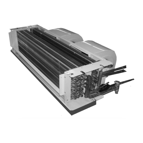
Multiaqua MACH-060-1 User manual

MACH Heat Pump Air-Cooled Chiller
Heat Pump Air-Cooled Chillers for Global Residential
and Light Commercial Microclimates

MACH-060 - 1
1 = 208/230-1-50/60
MACH NOMENCLATURE BREAKDOWN
Voltage
Air-Cooled Chiller
060= 60,0000 BTUH
1
MACH-060-1
Available Model Numbers

HVAC Guide Specifications
Heat Pump Air Cooled Liquid Chiller
Size Range:
5 Tons
Multiaqua Model Number:
MACH-060-1
Part 1 — General
1.01 SYSTEM DESCRIPTION
Multiaqua air cooled liquid heat pump chiller are designed using a scroll compressor, low sound condenser fans and a high
efficiency pump.
1.02 QUALITY ASSURANCE
A. Unit shall be certified in accordance with U.L. Standard 95, latest revision (U.S.A)
B. Construction shall comply with ASHRAE 15 Safety Code, NEC and ASME applicable codes (U.S.A. codes)
C. Manufactured in a facility registered to ISO 9002, Manufacturing Quality Standard.
D. ETL Certified.
E. Fully load run tested at the factory.
F. Damage resistant packaging.
1.03 DELIVERY, STORAGE AND HANDLING
A. Packaged and readied for shipment from the factory.
B. Unit controls shall be capable of withstanding 150F storage temperatures in the
control compartment.
C. Stored and handled per unit manufacturer’s recommendations.
1.04 WARRANTY
A. Complete unit, first year parts only warranty against manufacturer’s defects.
B. Compressor, years 2-5, parts only warranty against manufacturer’s defects.
Part 2 — Products
2.01 EQUIPMENT
A. General:
1. Factory-assembled, air cooled heat pump chiller.
2. Shall be assembled on heavy gauge steel mounting/lifting rails.
3. Contained within the unit cabinet shall be all factory wiring, piping controls, refrigerant
charge (R-407c), and special requirements prior to field start-up.
4. Brass body strainer with 20 mesh screen and blow down shall be supplied in cabinet as a
field installable accessory.
B. Unit Cabinet:
1. Cabinet shall be galvanized steel casing with a baked polyester powder finish.
2. Cabinet shall be capable of withstanding 500-hour salt spray test in accordance with the ASTM
(U.S.A) standard.
C. Condenser Fans:
1. 4-blade, condenser fans shall e direct-driven, aluminum construction, and shall be statically
and dynamically balanced with inherent corrosion protection.
2. Air shall be discharged horizontally.
3. Motors and fans shall be protected by coated steel wire safety guards.
D. Fan Motors:
1. Condenser fan motors shall be single speed, direct drive.
2. Totally enclosed.
3. Permanently lubricated sleeve bearings and Class F insulation.
4. Internal overload protection.
E. Compressors:
1. Fully hermetic scroll type compressor.
2. Direct Drive, 3500 rpm (50/60 Hz)
3. Compressor shall be suction gas cooled.
4. Internal motor protected.
5. Protected by high pressure and loss of charge devices.
6. External vibration isolation.
2

F. Pump:
1. Circulating pump shall be stainless steel with high efficiency enclosed motor.
2. Unit shall have chilled liquid solution piping to the exterior of the cabinet.
3. Shall have a max working pressure of 60 psig.
G. Evaporator:
1. Evaporator shall have one independent refrigeration circuit and one liquid solution circuit.
2. Rated for a refrigerant side working pressure of 450 psig and shall be tested for a maximum fluid-side
pressure of 150 psig.
2. Single pass, ANSI type 316 stainless steel, brazed plate construction.
4. Insulated with closed cell, elastometric foam (ASTM 518)
H. Condenser:
1. Shall be air cooled with integral sub-cooler.
2. One independent refrigeration circuit.
3. Constructed of rifled copper tubing mechanically bonded to aluminum fins.
3. Tubes shall be cleaned, dehydrated and sealed.
4. Assembled condenser coils shall be leak tested and pressure tested at 450 psig.
I. Refrigeration Components:
1. Refrigeration circuit components shall include sight glass, reversing valve, thermal expansion device,
and complete operating charge of both refrigerant (R-407c) and compressor POE oil.
PART 3-Controls and Safties
3.01 Controls
A. Controls:
Unit control shall include the following minimum components.
1. Control transformer to serve all controllers, relays and control components.
2. Pump bypass timer
3. Compressor recycle timer.
4. Optional low pressure bypass timer for low ambient operation.
5. Optional fan cycling control for low ambient operation.
6. Flow switch.
7. Defrost printed circuit board and thermostat.
8. Leaving water temperature thermostat with thermistors installed to measure cooler leaving water flow.
9. Manual heat/cool changeover switch.
B. Unit controls shall include the following functions.
1. Capacity control based on leaving chilled fluid temperature. Temperature setpoint accuracy of +/- 1.0F.
2. Chilled water pump start/stop control.
3.02 Safeties:
A. Unit shall be equipped with thermistors and all necessary components in conjunction with the control system
to provide the unit with the following protectants:
1. Low refrigerant pressure.
2. High refrigerant pressure.
3. Low liquid solution flow.
4 Thermal overload.
5. Short cycling.
PART 4 Operating Characteristics:
4.01 Temperatures
A. Unit shall be capable of starting and running in cooling mode at outdoor ambient temperatures from 55°F to
120°F.
B. Optional Low Ambient Kit shall allow starting and running at outdoor temperatures to – 20°F. A field supplied
and installed crankcase heater must be used when operating at these temperatures.
C. Unit shall be capable of starting and running in heating mode at outdoor ambient temperatures from 70°F
to 17°F.
D. Unit shall be capable of starting up in cooling with a maximum 80°F and a sustained 70°F entering liquid solution
temperature to the evaporator.
E. Unit shall be capable of starting up in heating with a minimum 55°F liquid solution temperature.
F. Minimum 10% Propylene Glycol solution is required. For outdoor temperatures below 32°, reference MAC
Glycol Solution Data Table.
3

4.02 Electrical Requirements
A. Primary electrical power supply shall enter the unit at a single point.
B. Electrical power supply shall be rated to withstand 120°F operating ambient temperature.
C. Unit shall be available in 208/230-01-50/60.
D. Control points shall be accessed through a terminal block.
4

5
MACH-060 Product Specifications
MACH060
Compressor Copeland
Scroll
Refrigerant R407c
Heat Exchanger Brazed Plate
Max. Pump Head
Pressure 50 ft.
Max Flow Rate 14.4 gpm
Min Flow Rate 9.0 gpm
Supply Water Temp 44°
Return Water Temp 54°
Min. Solution Content 25 Gallons
Expansion Tank Size 2 Gallons
Pump 0.5 HP
Water Connections 1" S & 1.25" R
Internal Pressure loss 1.85 ft of head
Multiaqua chillers are designed to operate exclusively with R407c refrigerant in a self-contained, pre-charged refrigerant system. Do not
access the closed refrigerant circuit for any reason other than after-sale, after installation component replacement. Routine maintenance
and service is to be performed by qualified personnel only.
These specifications are subject to change without notice.
Electrical Data
Compressor Condenser
Fan Motor
(2 qty) Pump Motor Fuse or HACR Circuit
Breaker Per Circuit
Model Number Volts/ Phase/
Hertz (RLA) (LRA) (FLA) (RPM) (FLA) (RPM) Minimum Amps Maximum
Amps
MACH060-01 208/230-1-50/60 32.1 169 1.05 1050 3.70 3450 45.93 70
Physical Data
Coil Chiller Weight (lbs)
Model
Number Height
(in) Length
(in)
Copper
Diameter
(in)
Coil
Rows Height
(in) Length
(in) Width
(in) Refrigerant
R407c Net Shipping
MACH060 38 48 3/8 2 49.75 39.75 16.25 92.95 oz 313 316
Copper Wire Size (1% Voltage Drop)
200 6 4 4 4 3 3 2 2
150 8 6 6 4 4 4 3 3
100 10 8 8 6 6 6 4 4
50 14 12 10 10 8 8 6 6
15 20 25 30 35 40 45 50
Supply Wire
Len
g
th in Feet
Supply Circuit Ampacity

6
MACH-060 Product Specifications
MACH-060 Capacity / Watts / EER
MACH060 COOLING MACH060 HEATING
O/A Temp (°F) Tons KW EER O/A Temp (°F) Tons KW EER
82 5.1 5.3 11.55 17 3.19 4.6 8.32
95 4.9 5.9 9.97 35 3.68 4.7 9.40
100 4.8 6.1 9.44 45 4.25 4.8 10.63
105 4.7 6.4 8.81 55 4.79 4.8 11.98
110 4.7 6.5 8.68 65 5.32 4.9 13.03
Notes: Cooling is based on 44°F leaving water temperature. Heating is based on 130°F leaving water temperature
Example: 30% glycol solution.
Maximum Flow Rate = 12gpm x 1.036
System capacity x .98
Use Propylene Glycol Only
Important
If the outside temperature is expected to fall below freezing (32°F) in the area the Multiaqua chiller is to be
installed; the installer must take the following precautions. Failure to do so will void the warranty.
To not engage in cold ambient mitigation will result in the failure of components such as the heat
exchanger, piping, circulating pump, etc… and or property damage.
• Keep the liquid solution at a minimum of ten percent propylene glycol even in areas where there is no danger
of freezing.
• The percentage amount of glycol recommended is dependent on the expected ambient temperatures and the
solution makeup recommendation of the glycol manufacturer. Refer to the Glycol Solution Data table above.
• Ensure the system circulating pump is in a constant energized mode to keep a continuous circulation of liquid
solution.
The Multiaqua chiller is a self-contained air-cooled condenser, coupled with an insulated brazed plate heat
exchanger (evaporator). The system utilizes a scroll compressor to circulate refrigerant between the condenser
and heat exchanger. The refrigerant is metered into the heat exchanger with a thermostatic expansion valve.
Protecting the system are high and low pressure switches as well as a pump flow switch.
Liquid solution (water and propylene glycol; minimum 10 % is required) is circulated through the heat
exchanger by an externally mounted pump. The liquid solution flows through the heat exchanger to the system
supply piping and on to the air handlers.
Low ambient kits are available for operating ambient temperatures down to -20 degrees Fahrenheit. The low
ambient kits consist of an ICM 325 (+) ICM (175) for single and three phase 208/230 vac chillers. For the three
phase 380/460 vac chillers a pressure activated fan control is used.
These specifications are subject to change without notice.
Glycol Solution Data
Propylene Glycol % Water Flow Capacity Min. Ambient Temp GPM Adjustment= 100% Capacity
10% x 1.020 x 0.99 26°F x 1.01
20% x 1.028 x 0.98 18°F x 1.03
30% x 1.036 x 0.98 8°F x 1.07
40% x 1.048 x 0.97 -7°F x 1.11
50% x 1.057 x 0.96 -29°F x 1.16

TONS GPM TONS GPM TONS GPM TONS GPM TONS GPM
35 3.90 3.70 3.60 3.50 3.50
40 4.50 4.30 4.20 4.10 4.10
42 4.80 4.60 4.50 4.30 4.40
44 5.10 4.90 4.80 4.70 4.70
45 5.30 5.10 5.00 4.80 4.80
46 5.40 5.20 5.10 5.00 5.00
48 5.80 5.60 5.40 5.30 5.30
50 6.10 5.90 5.70 5.60 5.60
55 7.00 6.70 6.40 6.30 6.20
60 7.80 7.50 7.30 7.10 7.00
TONS GPM TONS GPM TONS GPM TONS GPM TONS GPM
35 3.86 3.66 3.56 3.47 3.47
40 4.46 4.26 4.16 4.06 4.06
42 4.75 4.55 4.46 4.26 4.36
44 5.05 4.85 4.75 4.65 4.65
45 5.25 5.05 4.95 4.75 4.75
46 5.35 5.15 5.05 4.95 4.95
48 5.74 5.54 5.35 5.25 5.25
50 6.04 5.84 5.64 5.54 5.54
55 6.93 6.63 6.34 6.24 6.14
60 7.72 7.43 7.23 7.03 6.93
TONS GPM TONS GPM TONS GPM TONS GPM TONS GPM
35 3.82 3.63 3.53 3.43 3.43
40 4.41 4.21 4.12 4.02 4.02
42 4.70 4.51 4.41 4.21 4.31
44 5.00 4.80 4.70 4.61 4.61
45 5.19 5.00 4.90 4.70 4.70
46 5.29 5.10 5.00 4.90 4.90
48 5.68 5.49 5.29 5.19 5.19
50 5.98 5.78 5.59 5.49 5.49
55 6.86 6.57 6.27 6.17 6.08
60 7.64 7.35 7.15 6.96 6.86
7
These specifications are subject to change without notice.
105 110
110
12.0 12.0 12.012.0
12.0
82 95
12.0 12.0
12.0
MACH060 CAPACITIES with 20% Glycol
LWT (°F) ENTERING AIR TEMPERATURE (°F)
82 95 100 105
MACH060 Cooling Performance Data
12.0
MACH060 CAPACITIES with 0% Glycol
ENTERING AIR TEMPERATURE (°F)
82 95 100
12.0
105 110
LWT (°F)
12.0
LWT (°F)
12.0
MACH060 CAPACITIES with 10% Glycol
ENTERING AIR TEMPERATURE (°F)
100
12.0 12.0 12.0

TONS GPM TONS GPM TONS GPM TONS GPM TONS GPM
35 3.82 3.63 3.53 3.43 3.43
40 4.41 4.21 4.12 4.02 4.02
42 4.70 4.51 4.41 4.21 4.31
44 5.00 4.80 4.70 4.61 4.61
45 5.19 5.00 4.90 4.70 4.70
46 5.29 5.10 5.00 4.90 4.90
48 5.68 5.49 5.29 5.19 5.19
50 5.98 5.78 5.59 5.49 5.49
55 6.86 6.57 6.27 6.17 6.08
60 7.64 7.35 7.15 6.96 6.86
TONS GPM TONS GPM TONS GPM TONS GPM TONS GPM
35 3.78 3.59 3.49 3.40 3.40
40 4.37 4.17 4.07 3.98 3.98
42 4.66 4.46 4.37 4.17 4.27
44 4.95 4.75 4.66 4.56 4.56
45 5.14 4.95 4.85 4.66 4.66
46 5.24 5.04 4.95 4.85 4.85
48 5.63 5.43 5.24 5.14 5.14
50 5.92 5.72 5.53 5.43 5.43
55 6.79 6.50 6.21 6.11 6.01
60 7.57 7.28 7.08 6.89 6.79
TONS GPM TONS GPM TONS GPM TONS GPM TONS GPM
35 3.74 3.55 3.46 3.36 3.36
40 4.32 4.13 4.03 3.94 3.94
42 4.61 4.42 4.32 4.13 4.22
44 4.90 4.70 4.61 4.51 4.51
45 5.09 4.90 4.80 4.61 4.61
46 5.18 4.99 4.90 4.80 4.80
48 5.57 5.38 5.18 5.09 5.09
50 5.86 5.66 5.47 5.38 5.38
55 6.72 6.43 6.14 6.05 5.95
60 7.49 7.20 7.01 6.82 6.72
82 ENTERING AIR TEMPERATURE (°F)
MACH060 CAPACITIES with 30% Glycol
These specifications are subject to change without notice.
11010510095
12.012.012.012.0
12.012.0
MACH060 CAPACITIES with 40% Glycol
ENTERING AIR TEMPERATURE (°F)
100 110105
12.0
MACH060 Cooling Performance Data
95 100
12.0 12.0
110105
LWT (°F)
12.0
82 95
12.0
MACH060 CAPACITIES with 50% Glycol
LWT (°F) ENTERING AIR TEMPERATURE (°F)
82
LWT (°F)
12.0
8
12.012.0
12.0

TONS GPM TONS GPM TONS GPM TONS GPM TONS GPM
130 3.19 12 3.68 12 4.25 12 4.79 12 5.32 12
TONS GPM TONS GPM TONS GPM TONS GPM TONS GPM
130 3.16 12 3.64 12 4.21 12 4.74 12 5.27 12
TONS GPM TONS GPM TONS GPM TONS GPM TONS GPM
130 3.13 12 3.61 12 4.17 12 4.69 12 5.21 12
TONS GPM TONS GPM TONS GPM TONS GPM TONS GPM
130 3.13 12 3.61 12 4.17 12 4.69 12 5.21 12
TONS GPM TONS GPM TONS GPM TONS GPM TONS GPM
130 3.09 12 3.57 12 4.12 12 4.65 12 5.16 12
TONS GPM TONS GPM TONS GPM TONS GPM TONS GPM
130 3.06 12 3.53 12 4.08 12 4.60 12 5.11 12
Based on compressor data.
MACH060 CAPACITIES with 50% Glycol
LWT (°F) ENTERING AIR TEMPERATURE (°F)
17 35 45 55 65
LWT (°F) ENTERING AIR TEMPERATURE (°F)
17 35 45 55 65
MACH060 CAPACITIES with 10% Glycol
ENTERING AIR TEMPERATURE (°F)
45
MACH060 CAPACITIES with 30% Glycol
55 65
65
MACH060 Heating Performance Data
MACH060 CAPACITIES with 0% Glycol
ENTERING AIR TEMPERATURE (°F)
17 35 45 55 65
LWT (°F)
9
17 35
MACH060 CAPACITIES with 20% Glycol
LWT (°F) ENTERING AIR TEMPERATURE (°F)
17 35 45 55
These specifications are subject to change without notice.
LWT (°F)
LWT (°F) ENTERING AIR TEMPERATURE (°F)
17 35 45 55 65
MACH060 CAPACITIES with 40% Glycol

MACH060 Heat Pump Chiller Pump Curve
Pump Model Numbers
0.5 Horsepower
10
SSP-2 = 208/230/460-3-50/60
SSP-1 = 208/230-1-50/60

11

Page
Introduction 13
System Description & Sequence of Operation 14
Electrical & Physical Data 16
Service Clearances 17
Description of Electrical Controls 18
Chiller Controls Sequence of Operation 21
Refrigeration System Operation 23
Description of Refrigeration Components 24
Piping System Components 25
Layout & Design 26
Banked Chiller Configuration 27
Installation Notes 28
Propylene Glycol Content 29
Expansion Tank 29
Filling the System with Propylene Glycol 30
Air Elimination 30
Liquid Solution Balancing 31
Wiring Diagrams 32
Table of Contents
12

Multiaqua Heat Pump Chiller Manual
The Multiaqua Chiller System is the only air conditioning/refrigeration system of its kind in the world today offering the
degree of application flexibility described in the following manual.
The Multiaqua Chiller System is not only unique in its application flexibility; it is unique in superior quality, rated
capacity and rugged durability. When installed in accordance with these instructions the system will deliver years of
trouble free service.
Proper equipment sizing, piping design and installation are critical to the performance of the chiller. This manual is meant
to be a “how to” introduction to piping and installing the Multiaqua Chiller System.
RECOGNIZE THIS SYMBOL AS AN INDICATION OF IMPORTANT SAFETY OR
INSTALLATION RELATED INFORMATION.
Pressure loss information for a Composite Piping System has been used in preparing this manual. Web site information
addresses are supplied throughout this manual for piping and accessory information. The plumbing industry also has
pressure drop information on ferrous and copper piping systems, which will varyfromthe compositepipe system outlined
in this manual. Composite pipe is the recommended pipe for Multiaqua Chiller System installations; however existing
piping systems can be adapted to the system.
The following sections will describe each component, and how it functions within the system. Installation information
is supplied where appropriate. The piping design section ( page 26) will explain the design and layout out of the piping
system from a “how to” perspective. Following the examples provided will enable the installer to determine the correct
pipe and accessory sizing, as well as equipment location. It is important to know before installation if the proposed
system will operate correctly, and doing a formal layout of a new application or review of an existing piping system will
make that determination.
Throughout this manual the term liquid solution is used in place of water. The chiller circulates a solution of water
and Propylene Glycol.
It is essential to operate the system with a minimum of 10% propylene glycol.
DO NOT OPERATE THIS SYSTEM USING WATER ALONE!
FOR PROPER LIQUID SOLUTIONS MIX RATIOS, REFER TO PAGE 6 OR THE GLYCOL
MANUFACTURER’S RECOMMENDED MIX RATIOS.
13

System Description & Sequence of Operation
The Multiaqua MACH (Multiaqua Air Conditioning Heat Pump) is self-contained Reverse Cycle Chiller featuring dual
condenser fans, direct expansion outdoor coil (air side) and a brazed plate liquid solution heat exchanger (liquid side). The
outdoor coil acts as a condenser expelling heat from the refrigeration process in cooling and is an evaporator coil in the
reverse cycle heat pump mode. The MACH utilizes a SporlanTM thermostatic expansion valve (TXV) for the outdoor coil
and a piston type-metering device on the liquid solution heat exchanger. In the cooling mode the outdoor coil (condenser)
expansion/check valve is bypassing liquid refrigerant to the liquid solution heat exchanger (evaporator) metering
device. In the heating mode (reverse cycle) the outdoor coil (evaporator) expansion/check valve is receiving condensed
liquid refrigerant from the liquid solution heat exchanger (condenser) metering device. Integral safety features are included on
all models; including a low water flow control, a refrigerant high and low pressure switch and a five (5) minute delay on
break timer.
The system, depending on which mode has been selected (HEAT or COOL) will provide either a chilled or heated liquid
solution (water and Propylene Glycol mix). The solution temperature is controlled by the liquid solution temperature
control (DTC) which is factory set at 120°/44° (F). The liquid solution is circulated through the heat exchanger by an
internal stainless steel pump, which is protected with Silicon Carbide-Viton Seals, to the system supply piping and to
the airside fan coil/s.
The Pump will not self-prime. A full column of liquid solution is necessary for operation. Do not
attempt to operate the pump without a full charge of liquid solution or seal damage will occur.
If the external load is a series of fan coils, each one must contain an individual zone valve to control the liquid flow. The zone
valves are selected to provide the flow rate needed to achieve the proper capacity from the fan coil they control.
The temperature of the circulating liquid solution is controlled for either mode by a two (2) stage DTC (digital temperature
control) with adjustable set points for precision control. A system sequence of operation, individual control description,
troubleshooting information and a schematic are included in the controls section of this manual.
The liquid solution piping system suggested for new installations is a composite piping system. The composite system
delivers easy on installation, low-pressure drops and will not rust or corrode. Existing and new copper or ferrous piping
systems are adaptable to the Multiaqua system.
14

It must be recognized that ferrous pipe may cause accelerated deterioration of the brazed plate
heat exchanger and could void the heat exchanger warranty.
*Also Included in this manual is a piping section that includes piping system design, installation and balancing.
Equipment sizing for a Multiaqua solution system can utilize Load Diversity. Diversity is described as the
actual amount of cooling or heating needed by various sections of a structure at a given time. Conventional central ducted
air systems are designed for peak load conditions and must supply peak load capacity at all times to the conditioned space
whether or not a demand exists for other zones. This introduces great system inefficiencies. A system sized to take advantage
of diversity would determine the load by the time of day, building exposure, usage and adjust accordingly. To further define
load diversity a structure utilizing a conventional central ducted air system would require six (6) tons of capacity at peak load.
However, with the Multiaqua -MACH the specific load can be addressed and a smaller system utilized (potentially four (4)
or (5) tons instead of the full capacity’s 6 ton system. By taking advantage of load diversity, the system supplies the
necessary amount of capacity to the spaces or zones on an as needed basis instead of producing a larger capacity
100% of the time.
To clarify this concept we will adapt the above information to a basic Multiaqua System. Utilizing diversity and a MACH-
060 five (5) ton reverse cycle chiller we can supply chilled liquid solution to six (6) MHWW-12 (1) ton fan coils. Three (3) of
which are located in rooms facing west and three (3) in rooms facing east. Diversity dictates that the high load zones
(spaces) in a building need more cooling during different times of the day. A cooling load in the morning (AM) would
be greatest for portions of a structure facing east. During midday spaces with skylights or upper floors or multi-floor
structures impose more loads on the system. In the afternoon (PM) the load shifts to western facing spaces of the structure.
The Multiaqua system will adjust to load by supplying chiller or heated liquid solution to where and when it’s needed
depending on the changing load of the structure. In this simple example, it would be possible for a five (5) ton system to
handle what would normallybe a six-ton load on a conventionally ducted system.
Load diversity can best be determined by referring to the ACCA (Air Conditioning Contractors of America) Manual “J”,
refer to Appendix A-2, Multi-Zone Systems. ACCA can be located at the following Internet address: www.acca.org.
15

ELECTRICAL AND PHYSICAL DATA
The information contained in this manual has been prepared to assist in the proper installation, operation and
maintenance of the chiller. Improper installation, or installation not made in accordance with these instructions
can result in unsatisfactory operation and/or dangerous conditions and can cause the related warranty not to
apply.
Read this manual and any instructions packaged with separate equipment required to make up the system prior to
installation. Retain this manual for future reference.
Separate and independent power supplies and disconnects must be provided. These chillers have separate
and discreet power requirements within one cabinet.
All power to the chiller must be turned off prior to opening cabinet and or servicing.
Failure to properly ground chiller can result in death.
Disconnect all power wiring to chiller before maintenance or service work. Failure to do so can cause
electrical shock resulting in personal injury or death.
All wiring must be done in accordance with the NEC (National Electric Code) as well as state and local
codes, by qualified electricians.
Product warranty does not cover any damages or defect to the chiller caused by the attachment or use of
any components, accessories or devices (other than those authorized by the manufacturer) into, onto or in
conjunction with the chiller. You should be aware that the use of unauthorized components, accessories or
devices may adversely affect the operation of the chiller and may also endanger life and property. The
manufacturer disclaims any responsibility for such loss or injury resulting from the use of such unauthorized
components, accessories or devices.
Upon receiving the chiller and components, inspect for any shipping damage. Claims for damage, either
apparent or concealed should be filed immediately with the shipping company.
No liquid other than the solution of water and Propylene Glycol (mixed in accordance with table 6 page
32) shall be used in the piping system.
Corrosive environments may subject metal parts of the chiller to rust and deteriorate. The oxidation could
shorten the chiller’s useful life. Corrosive elements include salt spray, fog or mist in sea coastal areas, sulfur or
chlorine from lawn watering systems and various chemical contaminants from industries such as paper mills and
petroleum refineries.
If the unit is to be installed in an area where contaminates are likely to be a problem, special attention should be
given to the equipment location and exposure.
• Avoid having lawn sprinklers spray directly on the chiller cabinet.
• In coastal areas, locate the chiller on the side of the building away from the water front.
• Elevating the chiller off of its slab or base enough to allow air circulation will help avoid holding water in
contact with the cabinet base.
• Regular maintenance will reduce the build-up of contaminants and help protect the cabinet finish.
• In severe locations having the chiller coated with an “epoxy” or other coating formulated for air conditioning
systems located in coastal areas may be necessary.
16

Consult local building codes or ordinances for special installation requirements. When selecting a site
to locate the chiller, consider the following:
• A minimum clearance of 60” on the front fan discharge, 12” on the rear air inlet and a 24” clearance
is required on the service side.
• The chiller can be located out or indoors. If installed indoors there must be 4500 cfm of outdoor air changes
circulated through the mechanical room to sufficiently operate the chiller. No ductwork can be connected to the
chiller’s condenser or condenser fans.
• If a concrete slab is used, do not connect the slab directly to any building’s foundation or structure to prevent
sound transmission.
• Locate the slab on a level surface that is above grade to prevent ground water from entering the chiller cabinet.
Regular cleaning of the cabinet air filters will be necessary. The filters clean the air
which cools the circulation pump.
Stated Service Clearances
17
60” Front Fan Discharge Clearance
12” Rear Clearance
24” Side Service Clearance
Electrical
Connection
Service
Access
Return
Liquid
Solution
Connection
(
1.25”
)
Supply Liquid
Solution
Connection
(1”)

Control Transformer: The control transformer is rated at 24 vac, 40 va
(1.6 amps @ 24vac)
Pump Bypass Timer: The pump bypass timer is a 24 vac, 3-wire control.
When energized the timer will bypass the flow switch for 10 seconds (by
creating a circuit to the pump relay), energizing the pump relay, allowing the
pump to operate long enough to close the flow switch. In a normally operating
system the flow switch will stay closed powering the pump relay in series with
solution control contacts open, the timer delays by opening its contact for 5-
minutes before resetting to the closed position.
the low and high- pressure switches. Should the flow switch open, the timer
can only be reset by opening and closing the chiller's line voltage disconnect.
Refrigerant System Timer: The refrigerant timer is a 24 vac, 5-minute delay
Description of Electrical Controls
High Pressure Switch: The high-pressure switch is an automatic reset control
that senses compressor discharge line pressure. It opens at 400 PSIG and
closes at 300 PSIG.
on break, 20wire timer. The normally closed contacts of the timer energize
the compressor contactor through the chilled solution control. When the chilled
18

The low-pressure switch is an automatic reset control
closes at 80 PSIG.
Flow Switch: The flow switch senses liquid solution flow. The paddle of the
Pump Relay / Contactor: The pump relay energizes the pump through a normall
y
by 24 vac.
that senses compressor suction line pressure. It opens at 40 PSIG and
Description of Electrical Controls (continued)
Low Pressure Switch:
through the two or three normally open contacts. The contactor coil operates
(closes the contacts) when energized by 24 vac.
open contact. The pump relay coil operates (closes the contact) when energized
flow deflects the paddle closing the switch. The flow switch is position sensitive.
The arrow ↑on the switch must point in the direction of liquid solution flow.
Compressor Contacto
r
The compressor contactor energizes the compressor
19
switch is inserted through a fitting into the pump discharge line. Liquid solution
Table of contents
Other Multiaqua Heat Pump manuals
Popular Heat Pump manuals by other brands

Bryant
Bryant 548D Installation, Start-Up and Service Instructions

Accorroni
Accorroni GREEN 220 installation manual

Atlantic
Atlantic WOYG LCT Series Maintenance Document

Atlantic
Atlantic alfea extensa Series Installation and operating manual

Dimplex
Dimplex LI 11MER Installation and operating instructions

Whirlpool
Whirlpool WHP44 installation instructions