MYSTIC Circuits 3DVCA User manual

3DVCA Ofcial Manual
1

2

3DVCA Ofcial Manual
3
Contents
3DVCA 5
INSTALLATION 6
QUICK REFERENCE 8
FUNCTIONAL OVERVIEW 10
3 DIMENSIONS OF CONTROL 11
COMPASS DISPLAY 12
SCALING CURVES 13
INPUTS & OUTPUTS 14
NORMALIZATION ROUTING 15
SUMMING 16
PATCHING EXAMPLES WITH 3DVCA 17
MONO PATCHING WITH 3DVCA 18
STEREO PATCHING WITH 3DVCA 22
QUAD PATCHING WITH 3DVCA 26
CONTROL VOLTAGE PATCHING WITH 3DVCA 29

4

www.mysticcircuits.com
Flexibility is what makes modular synthesis so special. Every input
and output is a portal to new ways of making music. Each module that
you add to your case expands the possible signal routings of the other
modules in your case exponentially. 3DVCA is designed to automate
these routings and give you a exible tool to send or mix signals across
your case. Designed to be a highly customisable connection matrix,
3DVCA packs a boat load of utility into a small 6HP package. Four
VCAs share the three macro controls: X, Y, and Z. As a group, they
shape incoming or outgoing signals and emulate the coordinates of a
point in 3 dimensional space. They allow the VCAs to work together in
mono, stereo, or quad conguration and accomplish a variety of
mixing, crossfading, or panning functions. For easy integration with
multiple 3DVCAs or other mixer modules, each VCA output has a
dedicated sum input. This allows an entire mix to be automatically
passed along to the next mixer in the chain. Each module is built with
high quality components, Sound Semiconductor VCAs, and rail-to-rail
OPA family op amps. On top of that, each VCA is fully DC coupled to
work predictably with any type of signal you throw at it. Exponentially
expand the routing potential of your modular system with the Mystic
Circuits 3DVCA.
3DVCA Ofcial Manual
5

3DVCA Ofcial Manual
6
INSTALLATION
Follow the installation instructions carefully to avoid module or rack damage.
1. Ensure the power connection is off before installing the device.
2. Identify 6HP of free rack space in which to install the module.
3. Connect the 10 pin connector from the IDC ribbon power cable to the header on the
rear side of the module by aligning correctly with the red stripe on the ribbon conductor
nearest to the -12V pin indicator on the header.
4. Insert the cable through the rack and connect the 16 pin side of the IDC ribbon cable to
the rack power supply header. Ensure that the pins are aligned correctly with the red
stripe on the ribbon conductor nearest to the -12V pin on the header.
5. Position the module into the dedicated rack position.
6. Attach the 2 x M3 screws by screwing into the 2 locator holes and the rack mount
taking care to not over tighten the screws.
7. Turn on the power to the rack.
8. The module will start up and be ready to use.
Ensure the following conditions are correct for trouble free installation.
• Rack power supply can accommodate all of the installed modules total current ratings.
3DVCA power requirements are +12V 45mA, -12V 45mA, +5V Not Used.
• 3DVCA is 30mm deep.
• Module power cable orientation is correct at both the rack and module side. Use the
IDC ribbon cable supplied with the module.
• Ensure the rack earth / grounding is correct.
• Take care to avoid patch cables falling into the rack or touching module PCB’s

3DVCA Ofcial Manual
7
Power cable should only be connected
by 3DVCA with the red stripe aligned to
the red tag -12V on the power supply.
Connect power to the IDC Connector
Eurorack Installation.
-12V
-12V
Power
Power
Back
3DVCA

3DVCA Ofcial Manual
8
1
4
3
8
9
10
11
7 6
13
17
15
19
2
5
12
16
14
18
QUICK REFERENCE

3DVCA Ofcial Manual
9
6
8
11
12
2
Y Control. Fades Upper & Lower VCA Pairs On / Off. Crossfade in stereo congs.
Z Control. Turns all active 4 VCA’s On - Slider Up or Off - Slider Down.
Z CV Input. External control voltage modulation input.
X Control. Fades Left & Right VCA Pairs On / Off. Pan in stereo congurations.
X CV Input. External control voltage modulation input.
Compass. LED visualisation of the 4 VCA Channels.
NW Sum Input. Allows an input to be summed to the North West output
NE Sum Input. Allows an input to be summed to the North East output
Y CV Input. External control voltage modulation input.
SW Input. South West positioned input, normalised to South East Input.
SE Input. South East positioned VCA input.
NW Output. North West positioned output normalised to South West output.
NE Output. North East positioned output normalised to South East output.
SW Output. South West positioned output normalised to North East output.
SE Output. South East positioned VCA output.
The VCA Input / Outputs can be used in Mono, Stereo or Quad congurations. Arrows on
the panel indicate the normalization structure. Normalization is only performed when a
destination jack socket is unplugged.
NW Input. North West positioned input, normalised to North East & South West.
SE Sum Input. Allows an input to be summed to the South East output
SW Sum Input. Allows an input to be summed to the South West output
NE Input. North East positioned VCA input.
3
4
1
5
7
9
10
13
14
15
16
17
18
19

3DVCA Ofcial Manual
10
FUNCTIONAL OVERVIEW
Basics of a VCA.
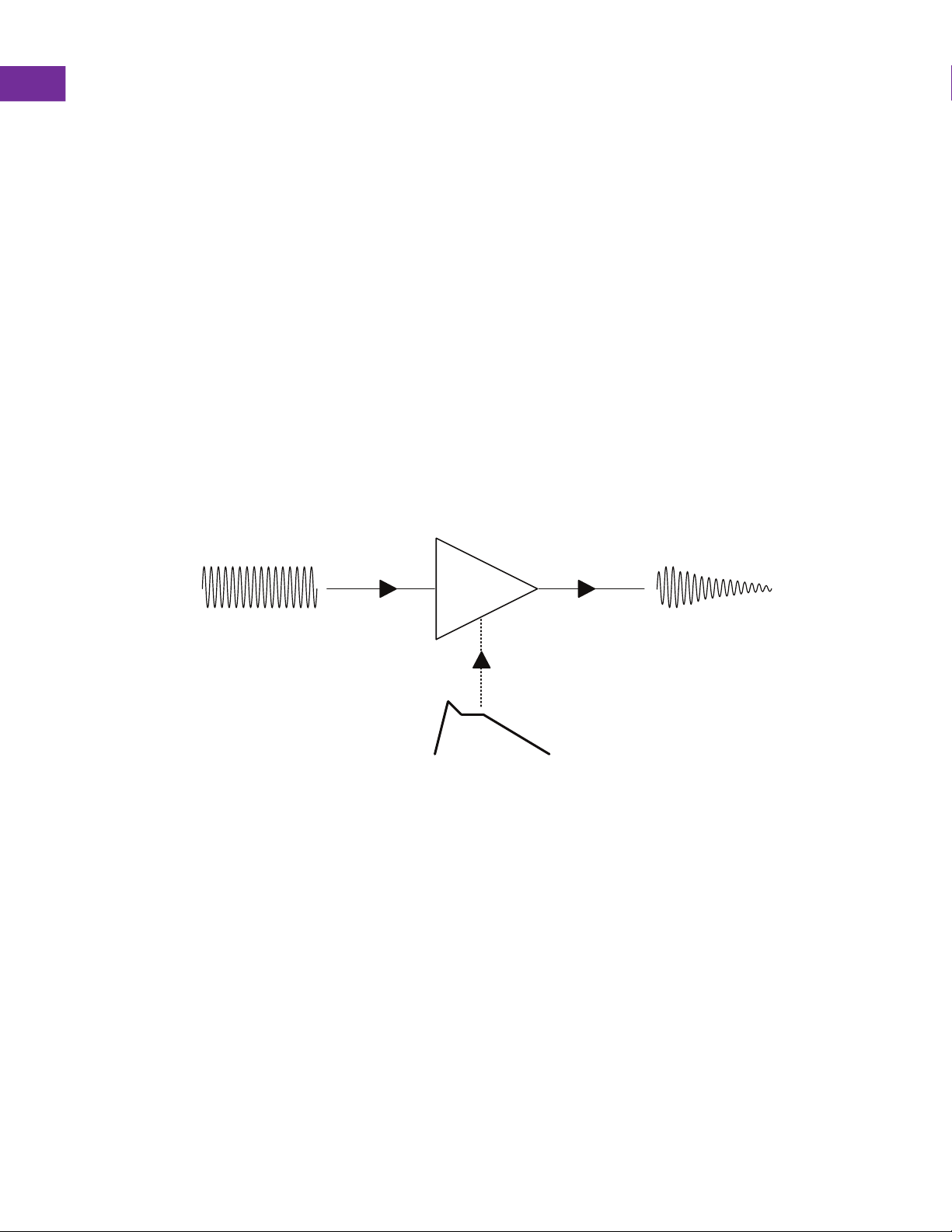
A VCA (Voltage Controlled Amplier) is a device that takes a voltage signal at the input
and adjusts the output level of that signal according to the level of a control voltage. This
function can be thought of as a voltage controlled attenuator. VCAs have the ability to
switch a signal on or off completely when controlled with a gate or gradually fade the
amplitude of that signal with a gradually changing control voltage. The most common use
of a VCA is to use an envelope to control the volume of an audio source in order to turn a
constant tone into more musical notes. In general, VCAs have a myriad of uses ranging
from adjusting the amount of modulation going to different control voltage inputs, changing
the volume of different notes in a sequence to allow accents or ghost notes, muting
voltage connections between different modules under voltage control, and so many other
functions. VCAs are probably the most important module in your system aside from audio
and CV signal generators.
Mystic Circuits 3DVCA - Quad Vector VCA.
Mystic Circuits 3DVCA is a quad VCA in a small 6HP form factor that can operate in mono,
stereo or quad congurations. Unlike a traditional quad VCA which allows independent
control over each VCA, 3DVCA uses 3 dimensional macro parameters to control all 4 VCA
channels together as a group. The X function gradually attenuates the Left / Right pairs of
VCA channels, the Y Function attenuates the Upper / Lower pairs of VCA channels and
the Z function controls the level of all active VCAs determined by the module's X and Y
settings.
The four VCA inputs and outputs are congured in a four quadrant conguration similar to
a geographic compass. As such, the 3DVCA LED display is called the ‘Compass’ and
visually represents the activity of all four VCAs. Similarly, the VCA inputs and outputs are
referred to as their corresponding North, East, South, and West positions. This will be
described in greater detail later in the manual.
Audio Input Modulation Input
Envelope CV
VCA
Audio output
Example: Generic VCA Principles

3DVCA Ofcial Manual
11
3 DIMENSIONS OF CONTROL
Instead of having control over each VCA individually, 3DVCA uses three Macro controls to
control all four VCAs as a group. This paradigm not only allows 3DVCA to be compact, but
also performs a variety of functions that benet from using the VCAs in tandem. Input and
output normalization make it easy to send one signal to multiple inputs or mix multiple VCA
outputs together in versatile ways.
The main parameters ‘X’, ‘Y,’ and ‘Z’ control the activity and overall level of the four VCAs
as if they behaved like a point in 3-dimensional space. Think of ‘X’ and ‘Y’ as controls over
the orientation of the point and ‘Z’ as the control over the distance. Although 3DVCA can
be patched in a variety of ways to change how it processes signals, these controls will
always work the same.
‘X’ gradually turns on or off the left and right pairs of VCAs.
‘Y’ gradually turns on or off the top and bottom pairs of VCAs.
‘Z’ changes the overall level of whichever VCAs are active depending on the ‘X’ and ‘Y’
settings.
With both ‘X’ and ‘Y’ in their center positions, all four VCAs will be active. From there you
can activate or deactivate any adjacent pair of VCAs or have only one of the four VCAs
active by adjusting ‘X’ and ‘Y.’ The current activity of all four VCAs is displayed in the
circular “compass” window between the ‘X’ and ‘Y’ knobs.
VCA1
Y
X Z
VCA2
3 Dimensional Control Concept
Control Point
VCA3
VCA4

3DVCA Ofcial Manual
12
COMPASS DISPLAY
The ‘Compass’ is the name given to the LED circular indicator that displays the status of
the four VCA’s. Each quadrant of the Compass represent the activity of one of the four
VCAs with a fully active VCA being fully illuminated and a fully inactive VCA being dark. As
mentioned before each VCA is denominated with an intercardinal direction which
corresponds to their direction on the compass: North West, North East, South East and
South West. The input and output position of each VCA will also correspond to their
assigned compass direction. Using either the panel controls or incoming modulation CV
determines the overall activity of all four VCAs.
Manual CV In Description
X Knob +/-10V
Fades on / off control for the East and West side VCA pairs.
The left and right channels of the will be balanced when set in
a stereo conguration and pan the input left and right in
Mono. The Panning feature is common to all VCA’s. The
range -10v to +10V is relative to the control knob. Full 10V is
needed if control is at the minimum position but +/-5V signal
will cover the full range if the knob is set at midpoint.
Y Knob +/-10V
Fades on / off control for the North and South VCA pairs. In a
standard stereo conguration the control will crossfade
between the two stereo sources. Full 10V is needed if control
is at the minimum position but +/-5V signal will cover the full
range if the knob is set at midpoint.
Z Slider 0-5V
Fades on / off control for all VCA’s simultaneously. This
function is still reliant on the X and Y controls determining the
active VCA’s. A 0-5V signal will sweep through full range.
North East VCANorth West VCA
Y ZAll
X
South East VCASouth West VCA
LED Indicator Compass
N
W
S
E

3DVCA Ofcial Manual
13
SCALING CURVES
Both the ‘X’ and ‘Y’ controls use an “equal power distribution” in order to keep the volume
of all of the inputs roughly the same when mixing many signals together or when only
hearing one output. This means that whenever multiple VCAs are active, there will be a
volume drop for any currently audible signals to compensate for the extra volume that
normally comes when mixing various signals together. In contrast the ‘Z’ parameter uses a
“linear power distribution” so that the overall volume of any currently audible signals will
track linearly with an incoming CV signal. This makes it easy to predict how a CV is going
to affect the level, but it comes with a downside: human hearing is actually logarithmic.
This means that the difference in volume will be more noticeable towards the bottom of the
‘Z’ slider rather than towards the top. This makes it seem like the volume turns up fast
when coming in from silent. We decided that it was more important to use a linear control
here than to have the volume change seem constant because it is much easier to use an
exponential envelope than it is to try and scale incoming CV to cancel out an exponent;
offering both as an option simply wasn’t possible due to space constraints. If you did not
understand this paragraph, don’t worry! It isn’t terribly important to the functioning of the
module, but it is still important to have access to this information.
VCA Gain
VCA Gain
X or Y
Equal Power Scaling
Scaling Examples
VCA1 VCA2
Gain for all 4 VCAs
Z
Linear Scaling

3DVCA Ofcial Manual
14
INPUTS & OUTPUTS
On the front panel, you will see two squares of jacks labeled with “IN” and “OUT” in their
respective centers. This is where you access the four VCAs. Each corner of each square
is connected through their respective VCAs and is reected by its position in the compass
window. Similar to a compass, we will be referring to these VCAs as compass directions:
the top left VCA is “North West”, the top right VCA is “North East”, the bottom right is
“South East” and the bottom left is “South West”. Similarly, any pair of VCAs can be
referred to by the cardinal directions of a compass; the top pair of VCAs are the “North”
VCAs, the bottom VCAs are the “South” VCAs, etc. This saves our ngers from having to
type “top left” a million times and is also a useful nomenclature that ts in with the
compass metaphor of our display.
North East
North East VCA
North West
North West VCA
South East
North East
South East
South East VCA
South West
North West
South West
South West VCA
Inputs - Upper Section
LED Indicator Compass
Outputs - Lower Section
N
W
S
E

3DVCA Ofcial Manual
15
NORMALIZATION ROUTING
The normalization pattern of the input and output jacks is notated on the panel using
arrows going between the various jacks. For those that don’t know, a normalized jack will
make a dedicated connection to another jack when nothing is plugged into it—that means
that you can distribute or mix a signal across multiple jacks without needing any external
modules. For example, when nothing is plugged into the NE input, it will borrow its input
signal from whatever is plugged into the NW input. This is marked by an arrow pointing
from the NW input jack towards the NE input jack. In contrast, if you to plug a signal into
the NE input jack, it will break the normalization connection and then the arrow and NW
input signal is ignored at the NE VCA input. This is where the true power of 3DVCA
resides: these normalization connections allow you to use 3DVCA in a multitude of
different functions without needing to use a large number of external mults or mixers.
North West Input
normalled to North East
& South West Input
North West Output
normalled to South West
Output
South West Input
normalled to South East.
South West Output
normalled to North East.
North East Input is
not normalled.
North East Input is
normalled to South
East Output.
South East Input is
not normalled.
South East Output is
not normalled.
Inputs - Upper Section
Outputs - Lower Section
The normalization pattern is different between the input and output squares—this pattern was
picked in order to make stereo patching more intuitive. When using the module in stereo, you can
usually treat the left and right inputs or outputs as left and right channels of your stereo signal. If
you want to mix two stereo signals together in this paradigm, then we want the outputs to mix
downwards with the NW output mixing into the SW output and the NE output mixing into the SE
output. In contrast, if you have a mono signal that you want to use in stereo patches, then the
signal must be distributed from left to right to share both sides of either the Northern or Southern
VCA pairs. This normalization scheme also lets you use the module in mono by distributing the
NW input to all four VCA inputs and mixing all four VCA outputs into the SE output.

3DVCA Ofcial Manual
16
SUMMING
The nal feature to explore on 3DVCA is the group of “SUM” inputs located on the left of
the panel. Each of these inputs mixes automatically into its dedicated VCA output with the
direction of the VCA labeled as a white square pointing away from the jack that it identies.
The sum inputs add a lot of utility to the module, allowing an entire mix to be made in
mono, stereo, or quad just by daisy chaining multiple 3VCAs together and even allow the
module to play nicely with other mixer modules by adding their output to your 3DVCA’s mix
effortlessly. When using 3DVCA in mono and listening to the SE output mixing all four
VCA outputs together, this section of the module functions as a four channel unity mixer
(essentially mixing 8 signals together with voltage control over four of those signals.) When
using 3DVCA in stereo, this section can mix in two other stereo pairs to tie your whole
patch together. When working in quad, each output of 3DVCA can be patched into the
sum inputs of the next 3DVCA in the chain, allowing 3DVCA to mix an entire quad patch
together with no other modules needed.
SUM
Summing occurs pre-normalization so the full mix is also normalled at the output destination. Only
signals plugged into the VCA inputs can be attenuated by 3DVCA (manually or with CV). Signals
patched into the SUM inputs will be heard at their incoming levels
Socket arrow tag image,
indicates NW destination.
Socket arrow tag image,
indicates SW destination.
Socket arrow tag image,
indicates NE destination.
Socket arrow tag image,
indicates SE destination.
Input here, sums into the
North West output signal
Input here, sums into the
South West output signal
Input here, sums into the
North East output signal
Input here, sums into the
South East output signal
Sum Inputs - Left Section

3DVCA Ofcial Manual
17
PATCHING EXAMPLES WITH 3DVCA
In the following section of the manual we will be showing a few examples of how to use
3DVCA in a patch. These examples will show some ways that we pictured 3DVCA in use
when designing the module. The following patches are meant to be building blocks to
inspire creative uses for 3DVCA in your synthesizer that you might nd yourself coming
back to often but are in no way comprehensive.
The examples to come are split into four different sections: patching in mono, patching in
stereo, patching in quad, and patching with control voltages. As you become more familiar
with 3DVCA, you might nd that you want to use a mono source in a stereo patch, use
stereo patching techniques to treat mono sources in parallel, or use one section of 3DVCA
for audio and another for control voltages. Having a solid understanding of the upcoming
example patches will give you the condence to approach these more complex functions
without getting lost in the details.
3DVCA is built with exibility in mind. This is why we gave the parameters abstract labels
like ‘X’, ‘Y’, and ‘Z’ instead of hard and fast labels that describe their function in every
scenario. While there are small labels next to each control which describe their suggested
function, the effect that each knob has on your signals will change depending on how
everything is patched. Therefore the function of these knobs, the ideal input or output to
use for a given purpose, and even the orientation to think of the signals owing through the
module is not the same in every patch.
The symbols used below will be used to designate certain kinds of signals in the upcoming
examples:
Audio Inputs
CV Inputs
Audio Outputs
All input and output jacks use a 1/8th / 3.5mm Mono jack plug. All Inputs and
Outputs are DC coupled which allows a full spectrum of unfettered sound
frequencies and is therefore more accommodating when using control voltages,
sequences and audio signals.

3DVCA Ofcial Manual
18
MONO PATCHING WITH 3DVCA
Patch Example 1: Crossfading between 4 Inputs
A good place to start with 3DVCA is mixing four signals together in mono. We start by
taking four audio signals from your favorite audio sources, plugging them into the four VCA
inputs, and then taking our output from the SE output. With both ‘X’ and ‘Y’ in their middle
positions, turning ‘Z’ up or down will turn on or off the entire mix of all four signals. Turning
‘Y’ up or down from this position will gently mix in or out the North or South pairs of VCAs,
while turning up or down ‘X’ from this position will do the same for the East and West pairs
of VCAs. Turning both ‘X’ and ‘Y’ completely up or down will allow us to pick out each of
these signals individually. Here, each combination of ‘X’ and ‘Y’ set to either their minimum
or maximum settings selects which corner you are isolating. You will notice that when only
one VCA is active, its signal gets a bit of a volume boost. But when you mix multiple
signals together, the volume is reduced. This is the “equal power distribution” we
discussed earlier at work—it makes sure that there are no signicant volume jumps no
matter where in the VCA compass we are.
Inputs - Upper Section
Outputs - Lower Section
All four VCA outputs will
be mixed into the SE
output socket.
Four individual audio
source signals.
X - Left / Right Crossfade | Y - Top / Bottom Crossfade
Z - Overall Level

3DVCA Ofcial Manual
19
Patch Example 2: Unity Mixer - 4 Sum Inputs to 1 Output
As mentioned before, in this patch we can also mix in four external signals into the “SUM”
inputs and have these signals mixed into our SE output. These inputs do not react to the
panel controls and so there should be no difference in volume when plugging into one
“SUM” input or another. This also means that there is not an easy way to mute this audio
unless it has an external volume control. It’s better to use the “SUM” inputs for signals that
have their own envelope, VCA, or volume control built in and to use signals that need their
volume shaped into the VCA inputs to take full advantage of each section of 3DVCA.
SUM
SUM Input Section
Outputs - Lower Section

3DVCA Ofcial Manual
20
Patch Example 3: Quad Panner - Pan 1 Input to 4 Outputs
A similar patch involves sending one signal to all four of 3DVCAs outputs. Start by
plugging your favorite signal generator into the NW input on 3DVCA and then plug all four
outputs of the output square into different destinations: either different effects, modulation
inputs, or wherever you might want to send a signal. As you can see from the input
normalization arrows, this NW input signal is now shared across all four of the VCA inputs.
Now the panel controls will function just as before but instead of controlling the input signal
levels, we are controlling the output signal levels. And like before, the overall volume will
be reduced when more than one VCA is active compared to when only one VCA is active
due again to the “equal power distribution.” We will examine using this same patch to work
in quad later in the manual.
Inputs - Upper Section
Outputs - Lower Section
X - Left / Right Pan | Y - Top / Bottom Pan
Z - Overall Level
Table of contents
Other MYSTIC Circuits Music Equipment manuals