Nadatel NCAM-370-X10 Installation and maintenance instructions

H.264 IP PTZ Camera Network Manual
IP PTZ
Camera
NCAM-370-X10
H.264 IP PTZ CAMERA
Network Manua
Ver. 1.0

4
H.264
IP PTZ Camera Network Manual
2/39
1. Introduction
About This Manual
3
Features
3
System Connections
4
2. System Operation
RemoteVideo Monitoring
6
Initialization o IP Address
7
3. True Manger
True Manager So tware
8
Server Registration and Removal
8
Server Connection Management
11
Server Status Monitoring
12
Network and System Diagnostics
13
F/W Upgrade
16
Remove Con iguration and Video Monitoring
16
4. Remote Configuration
Using Internet Explore
17
Use OSD (On Screen Display)
18
System Con iguration
19
Video Con iguration
21
Audio Con iguration
24
Network Con iguration
25
Serial Port Con iguration
28
Event Con iguration
30
Preset Con iguration
33
Record Con iguration
34
User Con iguration
38
C
ONTENTS

4
H.264
IP PTZ Camera Network Manual
3/39
About T is Manual
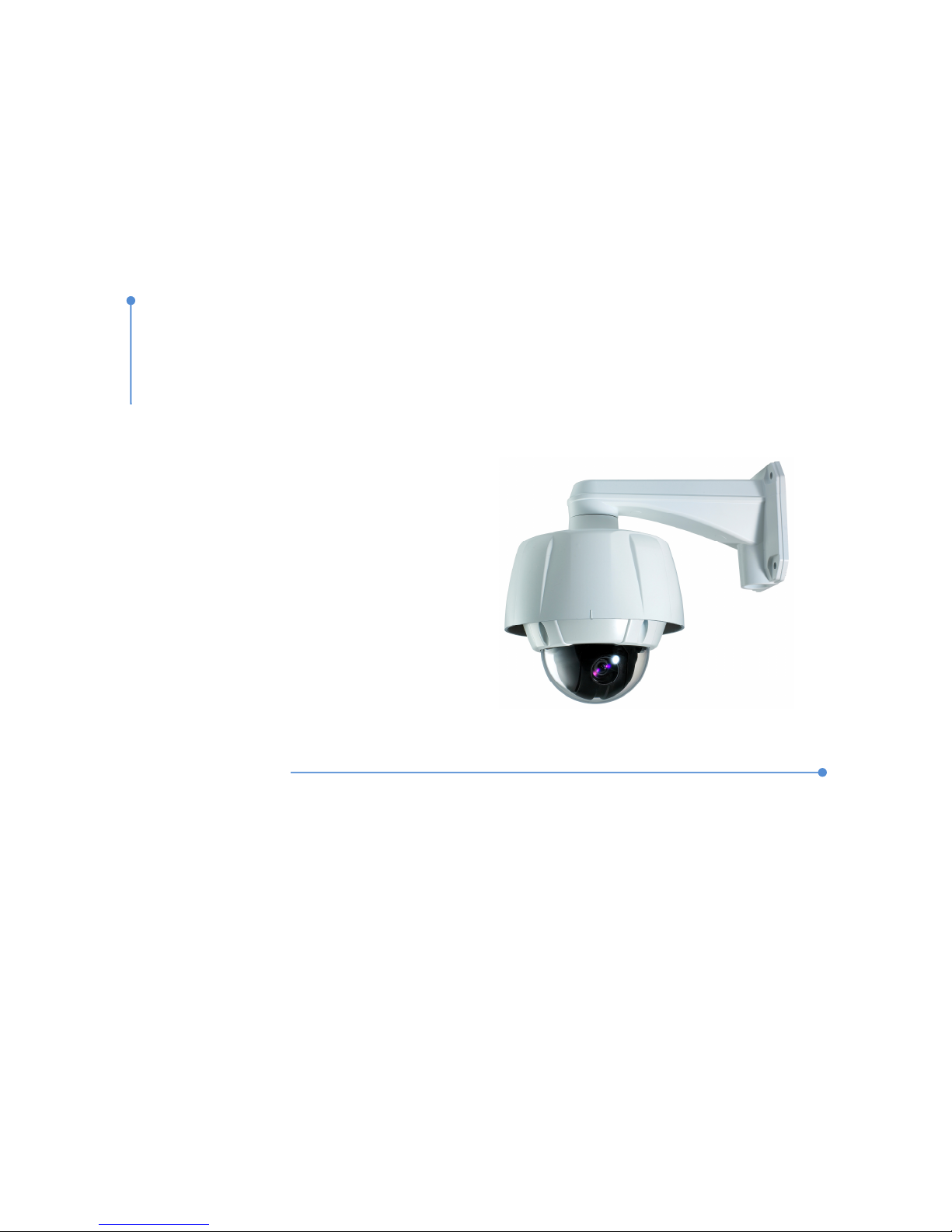
This User Manual provides in ormation on network part o IP PTZ Camera, NCAM-370. In this guide, in ormation on
operation and con iguration o NCAM-370 is explained as well as how to shoot troubles when problems arise.
Features
NCAM-370 is a video and audio surveillance transmission system based on IP network through LAN, ADSL/VDSL,
and Wireless LAN.
Video
Dual Streaming H.264 / MJPEG
Compression into Various Resolution : QCIF, CIF, Hal -D1, D1
Wide Range o Video Transmission Rate : 32kbps ~ 4Mbps
Various Transmission Mode : CBR, VBR
Motion Detection
Audio
Various Transmission Mode : Unidirectional Mode (NCAM-370 to Client PC or Decoder / Client PC or
Decoder to NCAM-370), Bi-directional Mode
Network
Static IP and Dynamic IP(DHCP) Support
One to One Connection and One to Multiple Connection
Multi-Casting
Automatic Transmission Rate Control by Network Condition
User Interface
System Status Display with OSD(On Screen Display)
System Con iguration via Internet Explorer
Reliability
Reliable Embedded System
System Recovery with Dual Watch-Dog Function
I
NTRODUCTION
1

4
H.264
IP PTZ Camera Network Manual
4/39
System Connections
NCAM-370 systems can be connected in either 1-to-1 ashion where a server is connected a PC client or a decoder
system or 1-to-multiple ashion where a server can be simultaneously connected to many PC and many decoder
systems.
Topology
Generally, the NCAM-370 and the PC & decoder are connected in 1-to-1 mode or 1-to-multiple connection is also
supported.
1:1 Connection (Unidirectional Transmission).
Mostly used con iguration is 1 to 1 connection. A NCAM-370 is installed at a site where video images can
be transmitted and a PC or a decoder is installed at a center location to receive and view the video images
on analog monitor. Audio data are trans erred in either direction.
1:N Connection (Unidirectional Transmission).
In this con iguration, a site can be monitored at many remote center locations. Although up to 64 PCs or
decoders can be connected to on NCAM-370, in the real network environment, network bandwidth can limit
the maximum connections.
Functionally, the CMS (Central Monitoring System) so tware can replace the decoder.
I
NTRODUCTION
1
NCAM-370 Decode
NCAM-370
Site
Remote
Center
PC
NCAM-370
PC/Decoder
PC/Decode
PC/Decode
Site
Remote Center
Site
Remote Center

4
H.264
IP PTZ Camera Network Manual
5/39
Multicast Mode
Within the network that supports multicasting, a large number o decoders can be used to receive video e ectively
rom a NCAM-370 using a single streaming o video and audio.
Relaying
In this arrangement, video and audio can be retransmitted rom a center to another center. The
arrangement is use ul when the network bandwidth to the site is limited while there is more than one center
wanting to monitor the site.
CMS(Central Monitoring System)
CMS (Central Monitoring System) is a Windows based remote monitoring program to access multiple IP-
severs or real-time monitoring or control o the encoders and connected cameras. Please re er to CMS
User Manual or more in ormation on CMS.
I
NTRODUCTION
1
NCAM-370
Site Remote Center #1
Decoder
Remote Center #2
Decoder
NCAM-370
Site
Remote Center
CMS
NCAM-370
Site
Remote Center
PC CMS

4
H.264
IP PTZ Camera Network Manual
6/39
Remote Video Monitoring
There are two ways to view video between the site and center system. In order or a proper operation, an IP address
must be set accordingly and please re er to True Manager in C apter 3 or Remote Setting in C apter 4 or a
urther details.
Default ID : admin Default Password : 1234
Video Monitoring wit Decoder System
Once the IP address is set in the remote IP address section o the decoder, the decoder system will connect to the
NCAM-370 and start receiving the video images. Normally, a monitor connected to the decoder will display video
images.
Video Monitoring using Internet Explorer
I an encoder’s IP address is entered on the Internet Explorer, the system will ask or con irmation to install Active-X
control. Once authorized, the Internet Explorer will start to display video images rom the encoder as shown below.
ttp://192.168.10.100
SYSTEM OPERATION
2

4
H.264
IP PTZ Camera Network Manual
7/39
Initialization of IP Address
I a system IP address is lost, the system can be reset to the system de ault IP address using the reset button in the
back side o the system.
①
While system is in operation, press the reset button or more than 5 seconds.
②
The system will reboot automatically
③
Once the system reboots, IP address will be set to the system de ault as below.
•
••
• IP mode Fixed IP •
••
• IP address 192.168.10.100
•
••
• Subnet mask 255.255.255.0 •
••
• Gateway 192.168.10.1
•
••
• Base port 2222 •
••
• HTTP port 80
SYSTEM OPERATION
2

4
H.264
IP PTZ Camera Network Manual
8/39
True Manager Software
True Manager is a program used or basic con iguration, diagnostics and F/W upgrade o NCAM-370. True
Manager provides the ollowing eatures.
Finding servers on the LAN and assigning IP address
Monitoring server status: encoding/decoding etc.
Diagnostic Function: Ping, Network Bandwidth Measurement, Video/Audio Output Port Check
F/W Upgrade
Server Registration and Removal
Server Registration
In order to manage servers using True manager, the irst step is to register the server. The ollowing steps describe
the way to register a server.
Select Add Server on Server menu.
Enter in ormation or connecting to the server at Add Server dialog.
USING TRUEMANAGER
3

4
H.264
IP PTZ Camera Network Manual
9/39
I the server is registered on DDNS server, domain name can be used instead o IP address. When the IP
address o the server is orgotten, it is possible to ind the IP address o the server with IP Discovery unction.
(Please re er to IP Discovery section).
Press Add button.
Removal of a server
A server can be removed by the ollowing steps.
Select a server to remove on Servers tab. The server should be highlighted with blue color.
Select Remove Server on Server menu.
Modification of information for a server
In ormation on a server can be modi ied on the dialog invoked by selecting Modify Server Info on Server menu.
USING TRUEMANAGER
3
Server selection

4
H.264
IP PTZ Camera Network Manual
10/39
IP Discovery
With IP Discovery unction, all servers on the same LAN where the PC executing True Manager is located can be
ound. Furthermore, it is possible to change IP address o a server easily. IP Discovery dialog is invoked by
pressing IP Discovery button on Add Server dialog, and it shows all NCAM-370s on the same LAN.
I you press Select button a ter selecting a server, the in ormation on the server is automatically entered on Add
Server dialog. Pressing IP C ange button a ter selecting a server invokes a dialog on which IP address o the
server can be changed.
It is possible to change IP address o a server which has IP address o di erent subnet.
Grouping of servers
When there are large numbers o servers, it is convenient to manage servers in several groups. Using Add Group
and Remove Group on Group menu, server group can be created and deleted. Modify Group menu is used to add
servers to a group or to remove servers rom a group.
USING TRUEMANAGER
3

4
H.264
IP PTZ Camera Network Manual
11/39
Server Connection Management
Server connection
I the check box on the irst column in Servers (or C annels/Perip eral) tab, True Manager tries to connect to the
server. I the server is running and the network where the server is in is normal, it will be connected immediately and
State will be changed to Connected.
I it ails to connect to the server due to server or network ailure, State displays Trying connection. As soon as the
server or network is recovered, it will be connected automatically. That is, True Manager periodically retries
connection to servers with check box checked
Server disconnection
I the check box is unchecked, the connection to the server is released and State displays Disconnected.
Check ox to connect or disconnect server
USING TRUEMANAGER
3

4
H.264
IP PTZ Camera Network Manual
12/39
Server Status Monitoring
Servers tab – General information
Servers tab shows general in ormation on a connected server: MAC address, product model, system mode(Type)
F/W version and startup time. This in ormation comes only or connected servers.
C annels tab - Monitoring of video/audio c annel state
C annels tab displays how video channel and audio channel o servers are working.
Item Displays
Ch Channel no.
Conns Number o clients connected to a server (including True Manager)
Cam Video loss status
Motion Motion status
V-E(kbps) Video encoding bitrate
V-E( ps) Video encoding ramerate
V-D(kbps) Video decoding bitrate
V-D( ps) Video decoding ramerate
A-E(kbps) Audio encoding bitrate
A-D(kbps) Audio decoding bitrate
Depending on the system mode, items which are not relevant to the mode may display 0 always. For example, V-
D(kbps) and V-D( ps) are always 0, i the system mode is Encoder.
Perip erals tab – Monitoring of serial, sensor and relay port
This unction is not available in this product.
USING TRUEMANAGER
3
USING TRUEMANAGER
3

4
H.264
IP PTZ Camera Network Manual
13/39
Network and System Diagnostics
True Manager provides various diagnostic eatures.
Connection between two NCAM-370s, or between NCAM-370 and CMS(Central Monitoring System) is
established.
Video, audio or serial data are not delivered as con igured.
Video and/or audio outputs don’t come on output port.
Ping test
Ping Test dialog can be invoked by selecting Ping Test on Tools menu a ter selecting a server.
Ping test is use ul or checking i one or more remote systems are reachable rom a server. Up to 4 systems can be
registered as the targets o Ping test, which makes it possible to identi y the hop(segment o network) where network
ailure may happen. For example, local router, remote router and remote Encoder can be pinged rom a Decoder
simultaneously.
Server executing Ping
Destination of Ping
USING TRUEMANAGER
3

4
H.264
IP PTZ Camera Network Manual
14/39
Network test
Network Test dialog is invoked by selecting Network Test on Tools menu.
Network test can be used or measuring e ective bandwidth and/or packet loss rate between a server and PC
running True Manager by generating test tra ic o constant bitrate. This eature is use ul or identi ying the reason
why video quality comes poorer than expected. TCP protocol can be selected or measuring e ective bandwidth,
while UDP protocol is appropriate or checking i the network is not reliable.
System test
Selecting System Test on Tools menu invokes a dialog on which system H/W status, video/audio output unction can
be diagnosed.
USING TRUEMANAGER
3

4
H.264
IP PTZ Camera Network Manual
15/39
System C eck
System C eck tests i H/W components are ine and board ID and MAC address are displayed.
Video Out C eck / Display Color Bar
It displays color bar on video output port. This unction works or Decoder or Duplex mode, and is use ul or
checking i video output port or external display device is normal.
Audio Out C eck / Play Audio Clip
It plays audio clip and outputs to audio output port. This unction is use ul or checking i audio output unction
o a server or external audio output devices such as ampli ier and speaker are normal.
Serial Loopback Test
This unction is not available in this product
Viewing server’s log
The log in a server can be viewed by selecting Log on Tools menu.
Remote rebooting of a server
A server can be rebooted by selecting Reboot on Tools menu.
USING TRUEMANAGER
3

4
H.264
IP PTZ Camera Network Manual
16/39
F/W Upgrade
When Update is selected on Tools menu, the dialog or F/W upgrade comes.
①
Select a server to upgrade (check the check box in Sel column). More than one server can be upgraded
simultaneously.
②
Select an upgrade ile.
③
Press Upgrade button.
④
Wait until Progress is changed to Upgrade succeeded.
Caution: Don’t power-off t e server w ile upgrade is in progress. T e server may go to irrecoverable
state
When network condition is poor, upgrade may ail. In such case, please retry above procedure a ter network
condition is recovered.
Remove Configuration and Video Monitoring
NCAM-370 provides web-based Setup and video viewing. I Setup on Server menu is selected, Internet Explorer is
invoked and page or remote setup o the server is displayed. I Viewer is selected on the menu, Internet Explorer
displays the video rom the server.
USING TRUEMANAGER
3

4
H.264
IP PTZ Camera Network Manual
17/39
Using Internet Explorer
The server can be con igured using web browser. Type IP address in the address input area o Internet Explorer,
then a live viewing screen will be displayed. Press Setup button located in the upper right area o the monitoring
screen, then the setup page or server setup will be displayed.
The con igurations are grouped into 8 categories: System, Video, Audio, Network, Serial, Event, Preset and User.
Any con iguration changes are not applied until Apply is pressed. Leaving the page without pressing Apply button,
changes in the page will be discarded.
REMOTE CONFIGURATION
4
Enter IP address
Press Setup utton

4
H.264
IP PTZ Camera Network Manual
18/39
Use OSD(On Screen Display)
Menu On Con igure System in ormation, Display setup, Camera setup, System initialization.
Please, re er to the camera part o NCAM-370 user manual or urther con iguration.
Enter Select and set Manu options
ESC Cancel setup and move to previous level.
Focus Near Focus Near is the same as Enter when OSD is activated.
Focus Far Focus Far is the same as ESC when OSD is activated.
Preset Move to desired view and press “Set” button. To move the set preset, press “GO to”
button. To remove the preset, press “Clear” button.
Max 248 presets are supported..
Pattern Conduct the pattern set on OSD. Max 4 patterns are supported.
Swing Conduct the swing set on OSD.
Group Conduct the group set on OSD.
4
IP-server
Site
Remote Center
PC/Decoder
PC/Decoder
PC/Decoder
REMOTE CONFIGURATION

4
H.264
IP PTZ Camera Network Manual
19/39
System Configuration
REMOTE CONFIGURATION
4

4
H.264
IP PTZ Camera Network Manual
20/39
System ID Alphanumeric System ID to be trans erred to remote so tware
Language Language to be used or web-based con iguration(English, Japanese and Korean)
Firmware version Current irmware version
Board ID Network board ID recognized by system
Upgrade Upgrade irmware
1. Press Browse button to select a irmware ile rom PC.
2. Press Firmware Upgrade button to start to upgrade.
3. Messages or showing status (downloading / upgrading) will be displayed.
4. The camera will reboot automatically a ter completing upgrade. Do not turn t e
camera off during upgrading
Start Time Latest system boot date and time
Current Time Enter a new date and time and press Set Current Time button to update date & time
Time Format Change the time ormat. Selectable time ormats are as below
- YYYY/MM/DD hh:mm:ss (Ex. 2010- 4-11 18:18:42)
- DD/MM/YYYY hh:mm:ss (Ex.11- 4-2010 18:18:42)
- MM/DD/YYYY hh:mm:ss (Ex. 4-11-2010 18:18:42
Time Zone Select time zone o where the system is installed. Depending on the time zone, Daylight
Saving Time will work automatically
Automatically
synchronize with
NTP server
Synchronize system time with an NTP server using NTP(network time protocol). Name
o the NTP server should be registered on NTP server Name.
Reboot Server Pressing Reboot Server button will cause the system to reboot. Do not press the
Reboot button unless the server needs a reboot.
Factory Reset Current IP Address is changed to de ault IP Address, 192.168.10.100. System log and
user registrations are also cleared. The other setting value will be remained
REMOTE CONFIGURATION
4
Table of contents