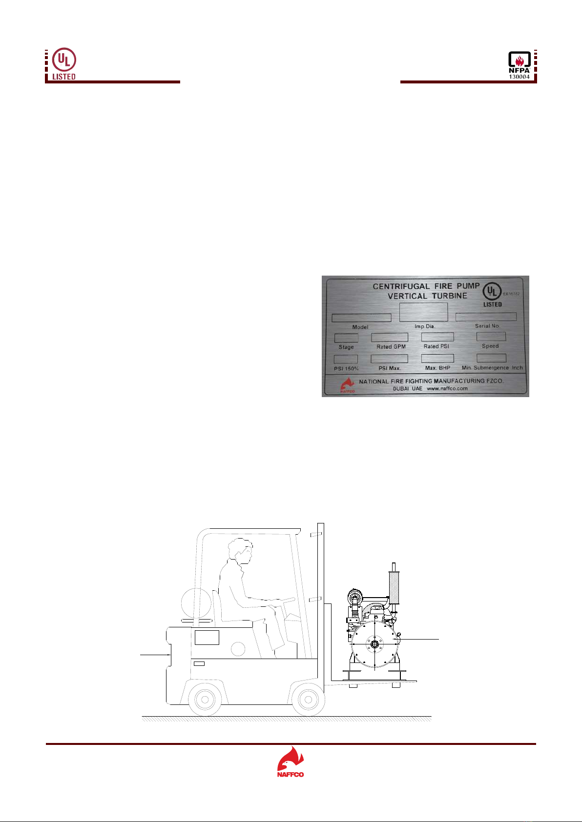
DO NOT OPERATE THIS PUMP AT ANY PRESSURE, FLOW
RATE, OR LIQUID TEMPERATURE OTHER THAN THOSE
WHICH SHOWN ON THE NAME PLATE. DO NOT PUMP
ANY LIQUID OTHER THAN WATER. IGNORING THIS
WARNING CAN RESULT IN PUMP FAILURE AND SERIOUS
PERSONAL INJURY OR DEATH.
1of 46
Subject to change without prior notice
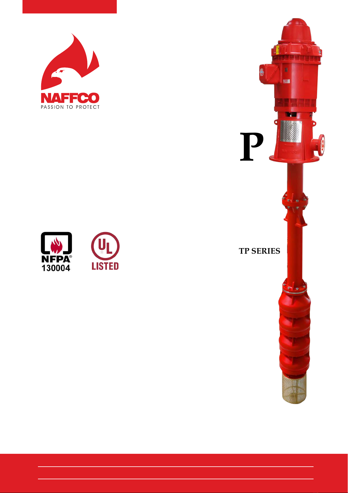
INSTALLATION OPERATION AND MAINTENANCE INSTRUCTIONS
FIRE PUMPS - NF-VTP SERIES
Ref. No. NFVTP-IOM/2016/V.02
1.1. General Safety Instructions
1.2. Electric Hazards
Check proper earth connection of the electric, diesel, jockey controllers and electric motors.
Make sure safety labels and operation labels are stuck in the controllers if damaged please get from NAFFCO and
replace.
Use only qualified personnel for installation and maintenance.
Electric motor cables terminals should be properly terminate and covered with terminal cover.
Inspect cable and connector if any damage replace immediately.
Do not keep tools on top of battery, this could result short circuit.
1.3. Mechanical Hazards
Wear eye protection during welding, grinding, drilling etc. Wear ear protection while operating diesel engine. Always
wear safety shoes and safety gloves.
Monitor water leakage of pump gland packing. If excessive leak adjust the packing, do not place hands or finger into
this area.
During maintenance disconnect battery negative terminal connector.
Do not refuel the engine when its running, fuel fumes are highly flammable.
Diesel engine exhaust pipe line should be insulated from temperature and it should be kept separate from discharge
line.
2. INTRODUCTION
This manual provides general instruction for the installation, operation, maintenance, dismantling and assembling of
vertical turbine fire pump manufactured by NAFFCO, U.A.E. Each centrifugal fire pump is tested in our factory as per
1. SAFETY
If the safety labels are missed or damaged, contact NAFFCO and get label and replace.
While starting pump set make sure pump set drive shaft guard fixed in the pump set.
Only proper tools of correct size shall be used for maintenance and service.
Do not wear loose clothing that could catch on moving parts.
Pump room should be kept clean from oil, waste cloth, water and easily explosive materials.
Pump room should not be treated a like store room.
Fire pump should be monitored during running to ensure that it was started due to an actual demand and water tank
should be monitored to avoid dry run condition.