Nagman HHP 100 User manual

Nagman®
HYDRAULIC HAND PUMP
HHP 400

NAG/IM/HHP 400/01/22 2
BRIEF PROFILE
An ISO 9001-2015 certified Instrumentation company
(since 1972) serving Industries in India & Worldwide thro’ the
Manufacture & Supply of World-Class Calibration
Instruments & Systems like Temperature, Pressure & Signal
Calibrators, Black Body Calibration Sources, Pneumatic &
Hydraulic Hand Pumps, Dead Weight & Comparison Testers,
Calibration Test Benches, etc.

NAG/IM/HHP 400/01/22 3
Dear User,
Thank you for selecting Nagman’s Hydraulic
Hand Pump and becoming a proud owner of
this Calibration Instrument.
We have strived hard to ensure the accuracy
of the contents of this manual. We would
appreciate any suggestions/feedback to
correct any errors noticed and to improve
the quality of contents of this Manual
Specifications are subject to change owing to
continuous development and we reserve
rights to effect Changes / Modifications to
this Manual.
Read the Instructions before starting to use
the Product.
Wishing you for a long association with us.
For any service related issues, please contact
VERSION CONTROL
Version No. Updated on Updated by
V 1.1 01.09.2022 Nagman

NAG/IM/HHP 400/01/22 4
CONTENTS
S.No. Description Page No.
1. Introduction …………………………………………………………..5
2. Specification…………………………………………………………….6
3. Standard Delivery & Optional Accessories ……………7
4. Parts Identification …………………………………………………8
5. Connection Diagram ………………………………………….…9
6. Safety Instructions ….…………………………………………..….10
7. Operating Instructions …………………………………………...11
8. Troubleshooting / Maintenance……………………………..15

NAG/IM/HHP 400/01/22 5
1. INTRODUCTION
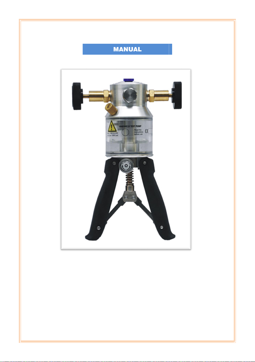
Nagman’s calibration hand pump is designed to manually
generate pressure between 100 / 200 / 350 / 400 bar
(depends on model).
This pump is manufactured with high quality components for
calibrating Analog / Digital gauges by comparison method. It
can be used for lab and field applications.
HHP is an ideal pressure source for calibrating pressure
transmitters, pressure transducers and pressure gauges.
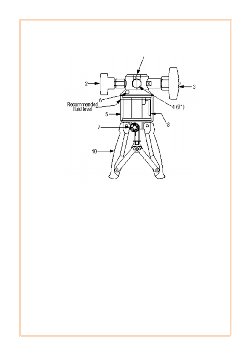
There is a Low / High pressure selector switch in the pump,
which is used for selecting low/high pressure output. It is
fitted with a fine Adjustment valve and a Release valve.
The output pressure / vacuum of the hand pump can be
adjusted precisely by the fine Adjustment valve while
calibration. Release valve is used for releasing the pressure /
vacuum after calibration.
The output pressure model ranges are :
Model
Range
HHP 100
Upto 100 bar
HHP 200
Upto 200 bar
HHP 350
Upto
350 bar
HHP 400
Upto 400 bar

NAG/IM/HHP 400/01/22 6
2. SPECIFICATION
Ranges Upto 200 / 350 / 400 bar
Gauge / Indicator Connection
Port
1/4” (F) BSP
Test Connection Port 1/4" (F) BSP
Medium Oil / (Water : Optional)
Oil Reservoir Material Transparent Acrylic
Reservoir Capacity 100 cc
Stabilization time 15 – 20 minutes
Instrument Dimension 240 x 185 x 95 mm (H x W x
D)
Instrument Weight (approx.) 1.26 Kg.

NAG/IM/HHP 400/01/22 7
3. STANDARD DELIVERY & OPTIONAL ACCESSORIES
Standard Delivery
Basic Pump
Hydraulic Oil : 100 cc
Cap for dust protection
Set of Seals
Conformance Certificate
Hydraulic Hose with end fittings (Length : 1 Meter)
Instruction Manual
Optional Accessories
Carrying Case (Soft/Hard)
Analog / Digital Pressure Gauges
Quick Connector
Spare Seals Kit
Water Operated Hand Pump
Set of Adaptors
⅛” BSP(F) X ¼” BSP (M)
½” BSP(F) X ¼” BSP (M) BSP
⅜” BSP(F) X ¼” BSP (M)
⅛” NPT(F) X ¼” BSP (M)
¼” NPT(F) X ¼” BSP (M) NPT
½” NPT(F) X ¼” BSP (M)
⅜” NPT(F) X ¼” BSP (M)

NAG/IM/HHP 400/01/22 8
4. PARTS IDENTIFICATION
1) Connection for ¼” BSP Male adapter to Master
Instrument.
2) Pressure Release Valve.
3) Fine Adjustment Valve
4) Front Port: 1/4” BSP female.
5) Reservoir
6) Reservoir Filling Plug / Safety valve
7) Low / High Pressure Selector.
8) Fluid Inlet tube.
9) Rear Port: ¼” BSP (F) reserved for Pressure Relief
Valve. (Do not open)
10) Pump Handles

NAG/IM/HHP 400/01/22 9
5. CONNECTION DIAGRAM
1. Master / Reference Measurement
2. Unit Under Test

NAG/IM/HHP 400/01/22 10
6. SAFETY INSTRUCTIONS
S. No. Symbol Description
1 Read the user manual before
operating the instrument.
2 Warning - conditions that may
pose hazards to the user.
3
Caution-conditions that may
damage the instrument.
4
Special Information

NAG/IM/HHP 400/01/22 11

NAG/IM/HHP 400/01/22 12
Do not release maximum pressure using Pressure
release valve, but use fine adjustment valve to
avoid damage to the instrument.
Do not exceed maximum pressure indicated on
pump label.
It is not advisable to use hydraulic oil operated
pump for water / oxygen ranges by removing oil
& replacing with distilled water & vice versa. Do
not use oil in water operated hand pump as it
would damage the inner seals & critical parts.

NAG/IM/HHP 400/01/22 13
7. OPERATION – PRESSURE / VACUUM
Remove reservoir filling plug (6) and fill reservoir (5)
with the oil / water (whichever specified) up to the
marked level and replace plug.
Turn pressure release valve (2) fully closed in
clockwise direction.
Operate fine adjustment valve (3) & bring it to ‘mid-
position’ in anti-clockwise direction.
Fully squeeze handles (10) in and turn Low / High
pressure selector (7) to low position.
The following figure shows the selector in Low
position
The following figure shows the selector in High
position
Connect the Master Instrument to pump (at the top)
through connection (1) using the appropriate seals
and adaptors.

NAG/IM/HHP 400/01/22 14
Connect the test instrument to flexible hose/gauge
adaptor and attach to pump through the quick-fit
connection (4).
Turn pressure release valve fully in anti-clockwise
direction.
Generate pressure by squeezing the pump handles
together.
Ensure selector position kept at Low and the handles
are fully squeezed together to achieve up to 30 bar
pressure and then change the selector position to
high for generating required maximum pressure
(depends on model).
Generate the remaining pressure using fine
adjustment valve by turning it in clock-wise direction.
Selection Low / High depends on the range and
easiness of generating of pressure with minimum
strokes.
Release the pressure using the fine adjustment valve
by turning it in anti-clockwise direction and then use
the pressure release valve by turning one turn in
clockwise direction.
After each operation (water medium), the
reservoir
must be emptied and let out dry.

NAG/IM/HHP 400/01/22 15
8. TROUBLESHOOTING / MAINTENANCE
If the HHP fails to develop the Pressure (Increase / Decrease)
even after considerable pumping action of the handle, check
the following:
Ensure that the connections between the pump, the
hose end and the Test / Master Instrument(s) are
tight and then retry pumping.
Check for any leak at all port connections, and ensure
for no trace of oil leak at connection ports.
Check that the Release Valve is fully closed.
Pump servicing work should be carried out only by
the manufacturer (Nagman).
Chances are there that one of the seals in the HHP is leaking
and needs to be replaced, if the applied pressure still cannot
be developed.
If functionality of HHP is not normal, please do not Continue
Pumping.
If functionality of HHP is not normal, please do not Continue
Pumping.

NAG/IM/HHP 400/01/22 16
Returning Instrument for Service
When returning the instrument to the manufacturer for
service, please provide complete information about the
problems faced for clear analysis of the problem. The
calibrator should be returned in the original packing.
Nagman‘s liability ceases if :
Parts are replaced / repaired using spare parts which are
not identical to those recommended by the
manufacturer.
Nagman‘s liability is restricted to errors that originated from
the factory.
For more details, write to :
NAGMAN INSTRUMENTS AND ELECTRONICS
PRIVATE LIMITED
170/1a2, Chennai Bangalore Highway Road,
Sembarambakkam, Chennai - 600 123. INDIA.
Phone:
+91-44-66777000, 0
11,
0
22,
0
33
Email:
W
ebsite : www.nagman.com
This manual suits for next models
3
Table of contents
Other Nagman Water Pump manuals