7
W415-1371 / 09.15.14
EN
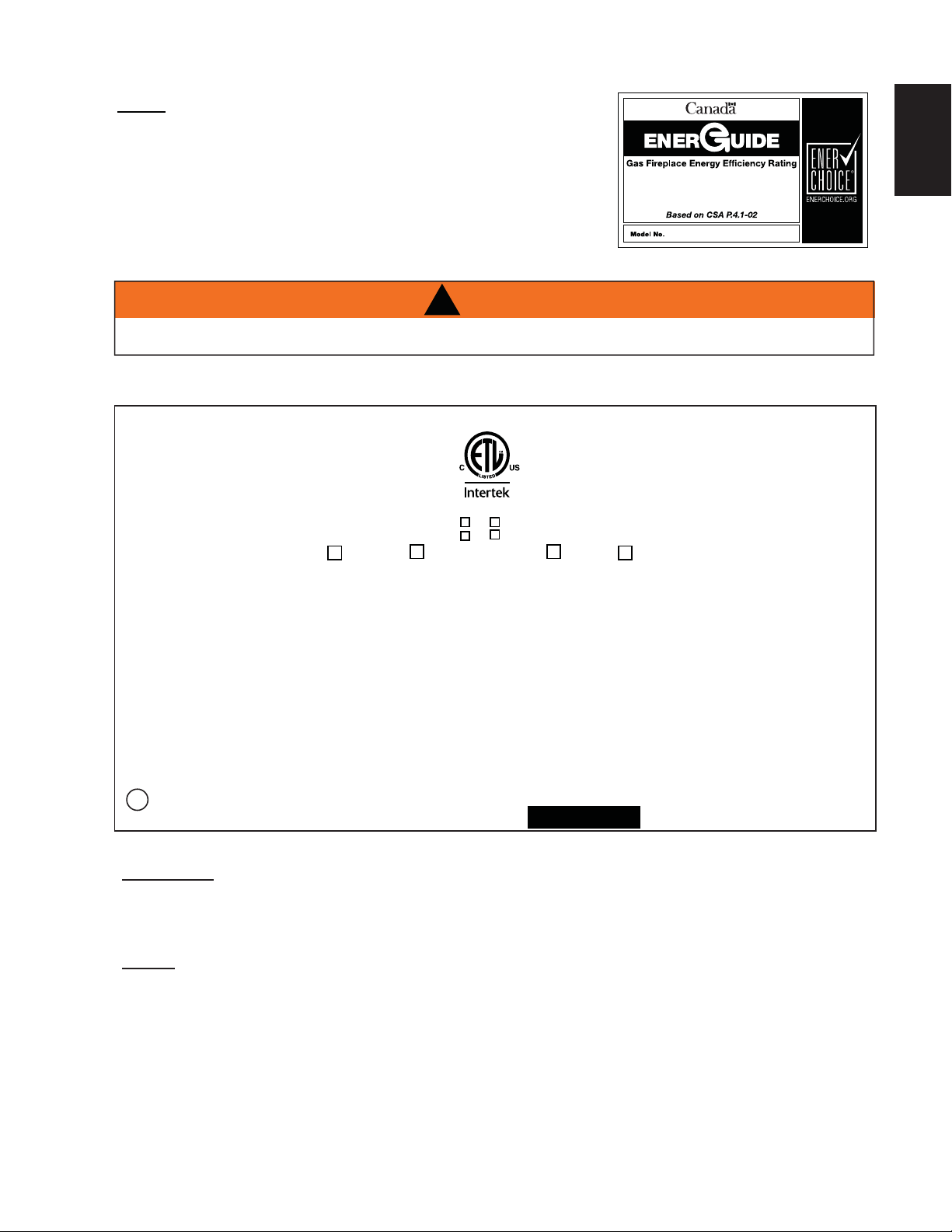
2.4 RATING PLATE INFORMATION
NOTE: The protective wrap on plated parts is best removed when
the assembly is at room temperature but this can be improved if
the assembly is warmed, using a hair dryer or similar heat source.
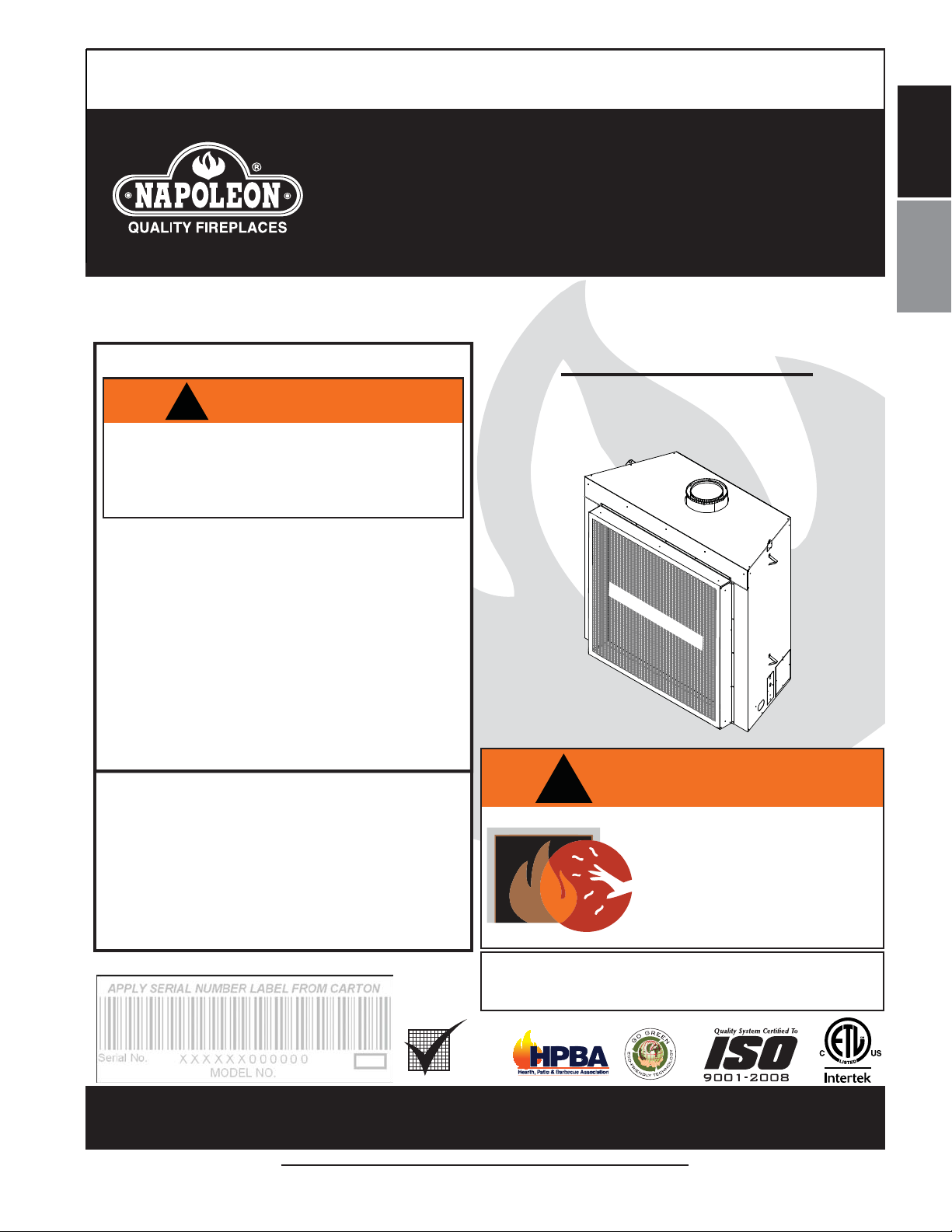
This appliance is equipped with a remote control system, which
requires batteries (supplied) to be installed. The transmitter takes 1
9V battery and in the case of a power failure the receiver takes 4 “AA”
batteries.
INSTALLER: It is your responsibility to check off the appropriate box on the rating plate according to
the model, venting and gas type of the appliance.
The illustration is for reference only. Refer to the rating plate on the appliance for accurate information.
NOTE: The rating plate must remain with the appliance at all times. It must not be removed.
65%
HDX52
Both the rating plate and lighting instructions are attached to a cable and inserted along the left side of the ap-
pliance.
!
WARNING
ALLOW APPLIANCE TO COOL BEFORE PERFORMING ANY MAINTANCE OR CLEANING.
W385-1928 / C
CHDX52N CHDX52P
CONFORMS TO / CONFORMEAUX: ANSI Z21.50-2014, CERTIFIED TO / CERTIFIE CSA2.22-2014 VENTED GAS FIREPLACE / FOYER À GAZ VENTILÉ.
DIRECT VENT GAS FIREPLACE.
NOT FOR USE WITH SOLID FUEL.
FOR USE WITH GLASS DOORS
CERTIFIED WITH THIS UNIT ONLY.
WARNING: DO NOT ADD ANY MATERIAL
TO THE APPLIANCE, WHICH WILLCOME IN
CONTACT WITH THE FLAMES, OTHER THAN
THAT SUPPLIED BY THE MANUFACTURER
WITH THE APPLIANCE
DECORATIVE PRODUCT: NOT FOR USE AS A
HEATING APPLIANCE.
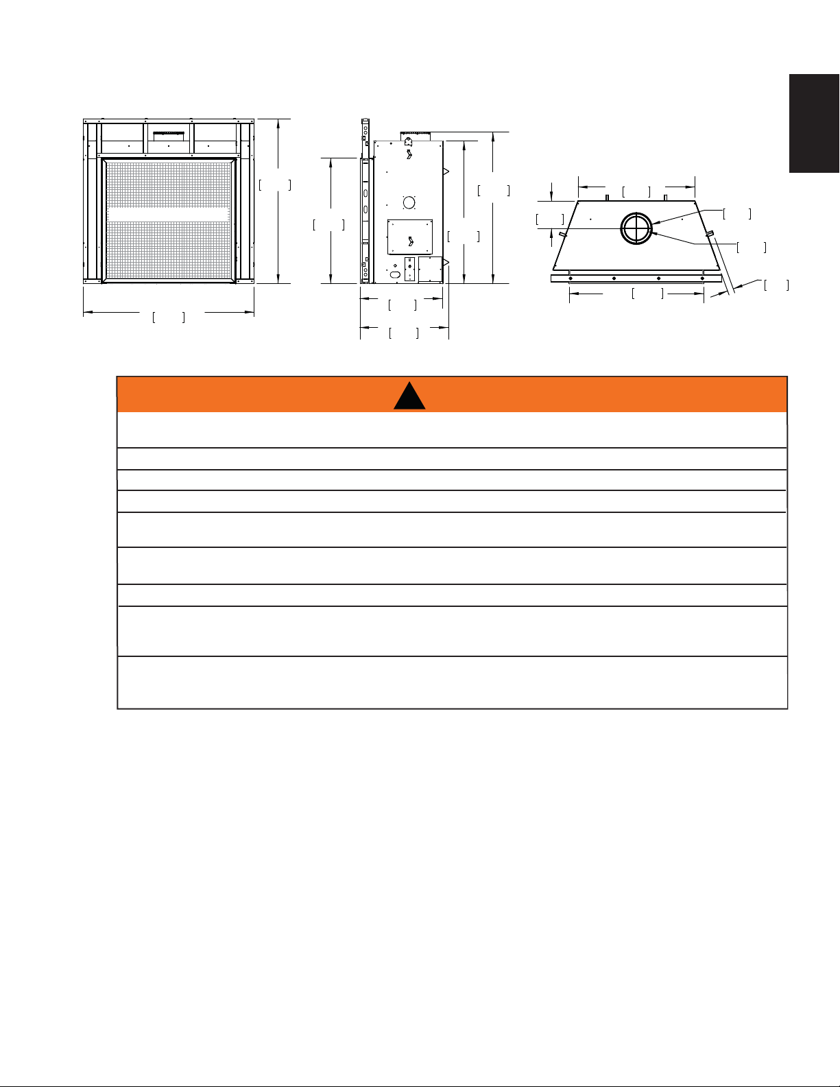
MINIMUM CLEARANCE TO
COMBUSTIBLE MATERIALS:
TOP 0"
FLOOR 0"
RECESSED DEPTH 29"
SIDES 0"
BACK 0"
VENT TOP 3"
VENT SIDES & BOTTOM 2"
VERTICAL VENT 1"
MANTEL 6"*
TOP SIDES & BACK: PER STAND OFF SPACERS FOR FRAMING
MATERIALS. FOR FINISHING MATERIALS SEE OWNER’S MANUAL
*MAXIMUM HORIZONTAL EXTENSION 2". SEE INSTRUCTION MANUAL FOR GREATER
EXTENSIONS. SEE OWNER’S INSTRUCTION MANUAL FOR MINIMUMAND
MAXIMUM LENGTHS.
ELECTRICAL RATING: 115V.60HZ. LESS THAN 12 AMPERES
WOLF STEEL LTD.
24 NAPOLEON ROAD, BARRIE, ON, L4M 0G8 CANADA
SPÉCIFICATIONS ÉLECTRIQUES : 115 V,
60HZ. MOINS DE 12 AMPÈRES.
HDX52N HDX52P
MODEL PROPANE /
PROPANE MODÈLE FOYER À D'ÉVENT DIRECT. UN
COMBUSTIBLE SOLIDE NE PAS
ÊTRÉ UTILISÉ AVEC CET
APPAREIL. UTILISER AVEC LES
PORTE VITRÉES HOMOLOGUÉES
SEULEMENT AVEC CETTE UNITÉ.
ADVERTISSEMENT : N’AJOUTEZ PAS
A CETAPPAREIL AUCUN MATÉRIAU DEVANT
ENTRER EN CONTACT AVEC LES FLAMMES
AUTRE QUE CELUI QUI EST FOURNI AVECT
CET APPAREIL PAR LE FABRICANT.
PRODUIT DÉCORATIF: NE PAS UTILISER
COMME APPAREIL DE CHAUFFAGE
DÉGAGEMENTS MINIMAUX DES MATÉRIAUX
COMBUSTIBLES :
DESSUS 0"
PLANCHER 0"
PROFONDEUR DE L’ENCLAVE FACE 29"
CÔTÉS 0"
ARRIÈRE 0"
DESSUS DU CONDUIT D’EVENT 3"
CÔTÉS ET DESSOUS DU CONDUIT
D’EVENT 2"
CONDUIT D’EVENT VERTICAL 1"
TABLETTE 6"*
DESSUS, CÔTÉS & ARRIÈRE : SELON LES ESPACEURS DE
DÉGAGEMENT POUR LES MATERIAUX D’OSSATURE SELON
LA MANUELDE PROPRIÉTAIRE POUR LES MATÉRIAUX DE
FINITION. *L’EXTENSION HORIZONTALE MAXIMALE : 2".
RÉFÉRER AU MANUALD’INSTRUCTION POUR DES
EXTENSIONS PLUS GRANDES. RÉFÉRER AU MANUEL
D’INSTALLATION DE PROPRIÉTAIRE.
MODEL NATURAL GAS /
GAZ NATURAL
0-4500FT (0-1370M) ALTITUDE / ÉLÉVATION 0-4500FT (0-1370M)
55,000 BTU/H
INPUT / ALIMENTATION 55,000 BTU/H
37,000 BTU/H REDUCED INPUT / ALIMENTATION RÉDUITE 36,500 BTU/H
3.5"WATER COLUMN/D’UNE COLONNE D’EAU MANIFOLD PRESSURE / 10"WATER COLUMN/D’UNE COLONNE D’EAU
PRESSION AU COLLECTEUR
4.5"WATER COLUMN/D’UNE COLONNE D’EAU MINIMUM SUPPLY PRESSURE / 11"WATER COLUMN/D’UNE COLONNE D’EAU
PRESSION D’ALIMENTATION MINIMALE
7.0"WATER COLUMN/D’UNE COLONNE D’EAU MAXIMUM SUPPLY PRESSURE 13"WATER COLUMN/D’UNE COLONNE D’EAU
PRESSION D’ALIMENTATION MAXIMALE
65.2% P.4 FE 65.2%
SERIAL NUMBER/ NO. DE SÉRIE: HDX52
L’APPAREIL DOIT ÉVACUER SES GAZ EN UTILISANT
L’ENSEMBLE D’ÉVACUATION PROPRE ANAPOLEON. RÉFÉRER
AU MANUEL D’INSTALLATION DE PROPRIÉTAIRE POUR
L’EVACUATION PRECISE. IL EST IMPORTANT DE BIEN
RÉINSTALLER ET RESCELLER L’EVENT APRÉSAVOIR ASSURÉ
LE MAINTIEN DU SYSTÉME DE PRISE D’AIR.
THE APPLIANCE MUST BE VENTED USING THEAPPROPRIATE
NAPOLEON VENT KITS. SEE OWNERS INSTALLATION MANUAL
FOR VENTING SPECIFICS. PROPER REINSTALLATIONAND
RESEALING IS NECESSARYAFTER SERVICING THE VENT-AIR
INTAKE SYSTEM.
THIS APPLIANCE MUSTBE INSTALLED IN ACCORDANCE WITH LOCALCODES, IFANY; IF NONE, FOLLOW THE
CURRENTANSI Z223.1 OR CSAB149, INSTALLATION CODES. VENTED GAS FIREPLACE.APPROVED FOR
BEDROOM, BATHROOM AND BED-SITTING ROOM INSTALLATION. SUITABLE FOR MOBILE HOME
INSTALLATION IF INSTALLED IN ACCORDANCE WITH THE CURRENT STANDARD CAN/CSA Z240MH SERIES
GAS EQUIPPED MOBILE HOMES, IN CANADA OR INTHE UNITED STATES THE MANUFACTURED HOME
CONSTRUCTION AND SAFETYSTANDARD, TITLE 24 CFR, PART 3280. WHEN THIS US STANDARD IS NOT
APPLICABLE USE THE STANDARD FOR FIRE SAFETY CRITERIA FOR MANUFACTURED HOME INSTALLA-
TIONS, SITES AND COMMUNITIES,ANSI/NFPA 501A. FOR USE WITH BARRIER W565-0148. FOLLOW THE
INSTALLATION INSTRUCTIONS LOCATED IN THE INSTALLATION MANUAL
INSTALLER L’APPAREIL SELON LES CODES D’INSTALLATION ANSI Z223.1 OU CSA-B149 EN VIGUER.
FOYER À GAZ VENTILÉ. HOMOLOGUÉ POUR INSTALLATION DANS UNE CHAMBRE À COUCHER, UNE SALLE DE
BAIN ET UN STUDIO.APPROPRIÉ POUR INSTALLATION DANS UNE MAISON MOBILE SI SON INSTALLATION
CONFORME AUX EXIGENCES DE LANORME CAN/CSA Z240MH SÉRIE DE MAISONS MOBILES ÉQUIPÉESAU
GAZ EN VIGEUR AU CANADAOU AUX ÉTATS-UNIS DE LA NORME DE SECURITE ET DE CONSTRUCTION DE
MAISONS MANUFACTUREE,TITRE 24 CFR, SECTION 3280. DANS LE CAS OU CETTE NORME D’ÉTATS-UNIS NE
PEUT ETREAPPLIQUÉE, SE REFERER ALA NORME RELATIVE AU CRITÈRE DE MESURES DE SÉCURITÉ
CONTRE L’INCENDIE POUR LES INSTALLATIONS DANS LES MAISONS MANUFACTURÉS, LES SITES ET LES
COMMUNAUTÉS, ANSI/NFPA 501A. POUR UNE UTILISERAVEC BARRIÈRE W565-0148. SUIVEZ LES
INSTRUCTIONS D'INSTALLATION SE TROUVENT DANS LE MANUEL D'INSTALLATION.
9700539 (WSL)
4001658 (NAC) 4001657 (NGZ)
4001659 (WUSA)
OPTIONAL FAN KIT: NZ64 ENSEMBLE DE VENTILATEUR FACULTATIF: NZ64


L(N,P)-1 Installation instructions and owner's manual")


(V/I)SB Installation and operating instructions")