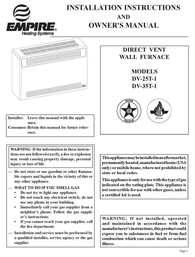
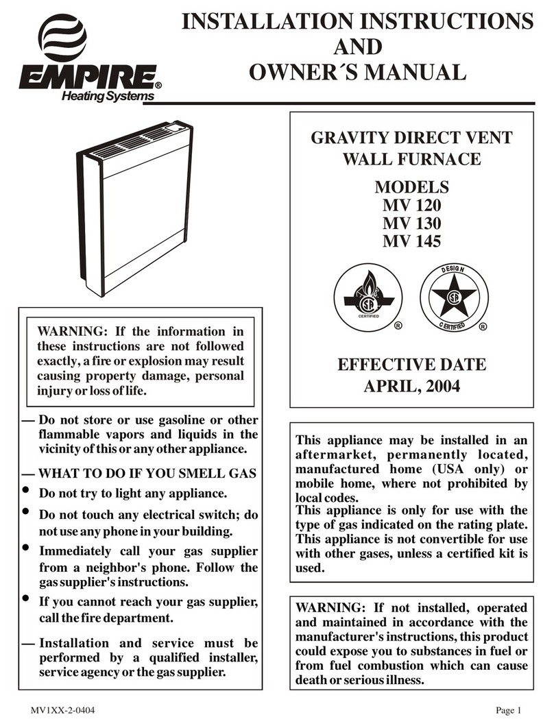
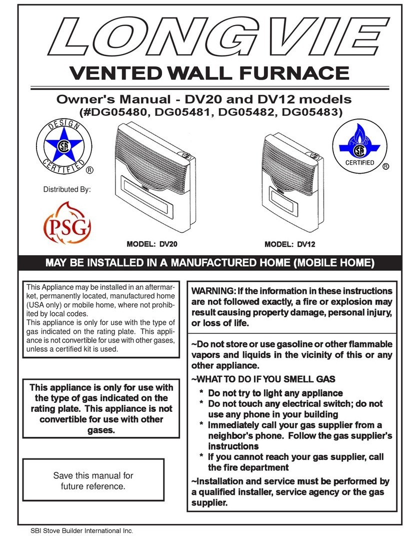
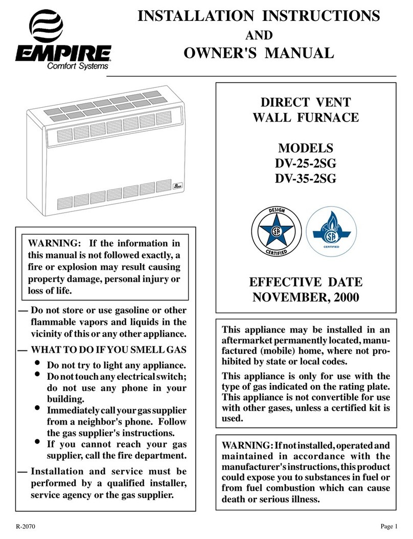
Napoleon GDS3700-N User manual

WS-415-63/11.24.98
GAS-FIREDGAS-FIRED
GAS-FIREDGAS-FIRED
GAS-FIRED GRAGRA
GRAGRA
GRAVITY DIRECT VENTVITY DIRECT VENT
VITY DIRECT VENTVITY DIRECT VENT
VITY DIRECT VENT WW
WW
WALL FURNACEALL FURNACE
ALL FURNACEALL FURNACE
ALL FURNACE
INSTINST
INSTINST
INSTALLAALLA
ALLAALLA
ALLATION AND OPERATION AND OPERA
TION AND OPERATION AND OPERA
TION AND OPERATION INSTRUCTIONS FOR:TION INSTRUCTIONS FOR:
TION INSTRUCTIONS FOR:TION INSTRUCTIONS FOR:
TION INSTRUCTIONS FOR:
NATURAL GAS MODEL
GDS3700 - NGDS3700 - N
GDS3700 - N
PROPANE GAS MODEL
GDS3700 - PGDS3700 - P
GDS3700 - P
INSTALLER: THESE INSTRUCTIONS MUST BE CONVEYED TO AND REMAIN WITH THE HOMEOWNER.
CERTIFIEDUNDERCANADIANAND AMERICAN NATIONAL STANDARDS, CSA 2.33 ANDANSI Z21.88 RESPECTIVELY FORVENTED GAS-FIRED SPACEHEATINGAPPLIANCES.
Fax:(705)722-6031 Email:[email protected]
Web:www.napoleon.on.ca
Wolf Steel Ltd., RR#1, 9 Napoleon Rd.,
Barrie, ON., Canada L4M 4Y8 (705)721-1212
R-2000
• Immediately call your gas supplier from
a neighbour's phone. Follow the gas
supplier's instructions.
• If you cannot reach your gas supplier,
call the fire department.
WW
WW
WARNING:ARNING:
ARNING:ARNING:
ARNING:
If the information in these instructions is not followed exactly, a fire or
explosion may result causing property damage, personal injury or death.
FOR YOUR SAFETYFOR YOUR SAFETY
FOR YOUR SAFETY
Do not store or use gasoline or other flammable vapours and liquids in the vicinity of
this or any other appliance.
WHAWHA
WHAWHA
WHATT
TT
TTT
TT
TO DO IF YOU SMELLO DO IF YOU SMELL
O DO IF YOU SMELLO DO IF YOU SMELL
O DO IF YOU SMELL GAS:GAS:
GAS:GAS:
GAS:
• Do not try to light any appliance.
• Do not touch any electrical switch.
• Do not use any phone in your building.
Installation and service must be performed by a qualified installer, service
agency or the gas supplier.

2
WS-415-63/11.24.98
PLEASE RETPLEASE RET
PLEASE RETAIN THIS MANUAL FOR FUTURE REFERENCEAIN THIS MANUAL FOR FUTURE REFERENCE
AIN THIS MANUAL FOR FUTURE REFERENCEAIN THIS MANUAL FOR FUTURE REFERENCE
AIN THIS MANUAL FOR FUTURE REFERENCE
TT
TT
TABLEABLE
ABLEABLE
ABLE ofof
ofof
of CONTENTSCONTENTS
CONTENTSCONTENTS
CONTENTS
PGPG
PGPG
PG 2-52-5
2-52-5
2-5 INTRODUCTIONINTRODUCTION
INTRODUCTIONINTRODUCTION
INTRODUCTION
Warranty
General Instructions
General Information
Care of Glass, Enamelled & Plated Parts
5-85-8
5-85-8
5-8 VENTINGVENTING
VENTINGVENTING
VENTING
Location and Clearances
Special Installation Example
Offset Installation Example
9-109-10
9-109-10
9-10 VENTING SPECIFICSVENTING SPECIFICS
VENTING SPECIFICSVENTING SPECIFICS
VENTING SPECIFICS
Horizontal Air Terminal Installation
Vertical Venting Installation
Stove Vent Connection
1010
1010
10 GAS INSTGAS INST
GAS INSTGAS INST
GAS INSTALLAALLA
ALLAALLA
ALLATIONTION
TIONTION
TION
1111
1111
11 FINISHINGFINISHING
FINISHINGFINISHING
FINISHING
Log Placement / Charcoal Embers
PGPG
PGPG
PG 1212
1212
12 OPERAOPERA
OPERAOPERA
OPERATION / MAINTENANCETION / MAINTENANCE
TION / MAINTENANCETION / MAINTENANCE
TION / MAINTENANCE
Operating Instructions
Maintenance
1313
1313
13 OPTIONAL BLOWER INSTOPTIONAL BLOWER INST
OPTIONAL BLOWER INSTOPTIONAL BLOWER INST
OPTIONAL BLOWER INSTALLAALLA
ALLAALLA
ALLATIONTION
TIONTION
TION
1313
1313
13 ADJUSTMENTSADJUSTMENTS
ADJUSTMENTSADJUSTMENTS
ADJUSTMENTS
Pilot Burner Adjustment
Venturi Adjustment
14-1514-15
14-1514-15
14-15 REPLACEMENTSREPLACEMENTS
REPLACEMENTSREPLACEMENTS
REPLACEMENTS
Ordering Replacement Parts
Replacement Parts
Accessories
Vent Kits
Terminal Kits
16-1716-17
16-1716-17
16-17 TROUBLE SHOOTING GUIDETROUBLE SHOOTING GUIDE
TROUBLE SHOOTING GUIDETROUBLE SHOOTING GUIDE
TROUBLE SHOOTING GUIDE

3
WS-415-63/11.24.98
NAPOLEON gas fireplaces are manufactured under the strict Standard of the world recognized
ISO9002 Quality Assurance Certificate.
NAPOLEON products are designed with superior components and materials, assembled by trained craftsmen
who take great pride in their work. The burner and valve assembly are leak and test-fired at a quality test
station. The complete fireplace is thoroughly inspected by a qualified technician before packaging to ensure that
you, the customer, receives the quality product that you expect from NAPOLEON.
NAPOLEON GAS FIREPLACE PRESIDENT'S LIFETIME LIMITED WARRANTYNAPOLEON GAS FIREPLACE PRESIDENT'S LIFETIME LIMITED WARRANTY
NAPOLEON GAS FIREPLACE PRESIDENT'S LIFETIME LIMITED WARRANTY
The following materials and workmanship in your newThe following materials and workmanship in your new
The following materials and workmanship in your new NAPOLEONNAPOLEON
NAPOLEONNAPOLEON
NAPOLEON gas fireplace aregas fireplace are
gas fireplace aregas fireplace are
gas fireplace are
warranted against defects for as long as you own the fireplace. This covers: combustionwarranted against defects for as long as you own the fireplace. This covers: combustion
warranted against defects for as long as you own the fireplace. This covers: combustion
chamber, heat exchanger, stainless steel burner, phazer™ logs and embers, ceramic glasschamber, heat exchanger, stainless steel burner, phazer™ logs and embers, ceramic glass
chamber, heat exchanger, stainless steel burner, phazer™ logs and embers, ceramic glass
(thermal breakage only), gold plated parts against tarnishing, porcelainized enamelled com-(thermal breakage only), gold plated parts against tarnishing, porcelainized enamelled com-
(thermal breakage only), gold plated parts against tarnishing, porcelainized enamelled com-
ponents and aluminum extrusion trims.ponents and aluminum extrusion trims.
ponents and aluminum extrusion trims.
Electrical (110V and millivolt) components and wearable parts such as blowers, gas valves,Electrical (110V and millivolt) components and wearable parts such as blowers, gas valves,
Electrical (110V and millivolt) components and wearable parts such as blowers, gas valves,
thermal switch, switches, wiring, remote controls, ignitor, gasketing, and pilot assembly arethermal switch, switches, wiring, remote controls, ignitor, gasketing, and pilot assembly are
thermal switch, switches, wiring, remote controls, ignitor, gasketing, and pilot assembly are
covered andcovered and
covered and NAPOLEONNAPOLEON
NAPOLEONNAPOLEON
NAPOLEON will provide replacement parts free of charge during the firstwill provide replacement parts free of charge during the first
will provide replacement parts free of charge during the firstwill provide replacement parts free of charge during the first
will provide replacement parts free of charge during the first
year of the limited warranty.year of the limited warranty.
year of the limited warranty.
Labour related to warranty repair is covered free of charge during the first year. RepairLabour related to warranty repair is covered free of charge during the first year. Repair
Labour related to warranty repair is covered free of charge during the first year. Repair
work, however, requires the prior approval of an authorized company official. Labour costswork, however, requires the prior approval of an authorized company official. Labour costs
work, however, requires the prior approval of an authorized company official. Labour costs
to the account ofto the account of
to the account of NAPOLEONNAPOLEON
NAPOLEONNAPOLEON
NAPOLEON are based on a predetermined rate schedule and any repairare based on a predetermined rate schedule and any repair
are based on a predetermined rate schedule and any repairare based on a predetermined rate schedule and any repair
are based on a predetermined rate schedule and any repair
work must be done through an authorizedwork must be done through an authorized
work must be done through an authorized NAPOLEONNAPOLEON
NAPOLEONNAPOLEON
NAPOLEON dealer.dealer.
dealer.dealer.
dealer.
CONDITIONS AND LIMITCONDITIONS AND LIMIT
CONDITIONS AND LIMITAA
AA
ATIONSTIONS
TIONSTIONS
TIONS
NAPOLEON warrants itsproducts againstmanufacturing defectsto theoriginal purchaseronly --i.e., theindividual orlegal entity(registered customer) whosename appearson the
warrantyregistrationcard filed withNAPOLEON -- providedthatthepurchase was madethroughanauthorized NAPOLEONdealerand issubjecttothe following conditionsandlimitations:
Thisfactory warrantyis nontransferableand maynot be extended whatsoever byany ofour representatives.
Thegas fireplacemust beinstalled bya licenced,authorized servicetechnician orcontractor. Installationmust bedone inaccordance withthe installationinstructions includedwith
theproduct andall local andnational buildingand fire codes.
This limited warranty does notcover damages caused bymisuse, lack of maintenance,accident, alterations, abuse orneglect and parts installed fromother manufacturers willnullify
this warranty.
Thislimited warranty furtherdoesnot cover anyscratches,dents, corrosionordiscolouring caused byexcessiveheat, abrasive andchemicalcleaners norchippingon porcelain enamel
parts,mechanical breakageof PHAZER™logs andembers, nor any venting components used inthe installationof thefireplace.
NAPOLEON warrants its stainless steel burners against defects in workmanship and material for life, subject to the following conditions: During the first 10 years NAPOLEON will
replace or repair the defective parts at our option free of charge. From 10 years to life, NAPOLEON will provide replacement burners at 50% of the current retail price.
Inthe firstyearonly,this warrantyextendsto therepair or replacementof warrantedpartswhich aredefective in materialor workmanshipprovided that theproduct hasbeen operated
inaccordance withthe operationinstructions and under normal conditions.
Afterthe firstyear,with respectto this President'sLimited Lifetime Warranty, NAPOLEONmay, at itsdiscretion, fullydischarge all obligationswith respecttothis warrantyby refunding
tothe originalwarranted purchaserthe wholesaleprice ofany warrantedbut defectivepart(s).
Afterthe firstyear, NAPOLEONwill notbe responsiblefor installation,labour orany othercosts orexpenses relatedto thereinstallation ofa warrantedpart, andsuch expensesare
notcovered bythis warranty.
Notwithstandingany provisions containedin this President'sLimitedLifetime Warranty,NAPOLEON’S responsibility underthis warranty isdefined as aboveandit shallnotin any event
extendto anyincidental,consequential orindirect damages.
Thiswarrantydefines theobligationsandliability ofNAPOLEONwith respect tothe NAPOLEON gasfireplaceandany otherwarrantiesexpressed or impliedwithrespectto thisproduct,
itscomponents oraccessories areexcluded.
NAPOLEON neither assumes,nor authorizes anythird partyto assume,on itsbehalf, any otherliabilities withrespect tothe sale ofthis product.NAPOLEON will notbe responsible
for:over-firing, downdrafts,spillage causedby environmentalconditions suchas rooftops,buildings, nearbytrees, hills,mountains, inadequatevents orventilation, excessiveventing
configurations,insufficient makeup air, or negative air pressures which mayor maynot becaused bymechanical systems such as exhaust fans, furnaces, clothes dryers, etc.
Any damages to fireplace, combustionchamber, heat exchanger, brasstrim or othercomponent due to water, weather damage,long periods of dampness, condensation,damaging
chemicals or cleaners will not be the responsibility of NAPOLEON.
The bill of sale or copy will be required together with a serial number and a modelnumber when making any warranty claims from your authorized dealer. The warranty registration
cardmust bereturned withinfourteen daysto registerthe warranty.
NAPOLEONreserves theright tohave its representative inspect any product or part thereof prior to honouring any warranty claim.
ALLSPECIFICATIONS AND DESIGNS ARESUBJECT TOCHANGE WITHOUT PRIORNOTICE DUETO ON-GOING PRODUCTIMPROVEMENTS. NAPOLEON®IS AREGISTERED
TRADEMARKOFWOLFSTEEL LTD. PATENTS U.S.5.303.693.801-CAN.2.073.411,2.082.915.©WOLFSTEELLTD.
4
WS-415-63/11.24.98
GENERAL INSTRUCTIONSGENERAL INSTRUCTIONS
GENERAL INSTRUCTIONS
ALL HORIZONTALL HORIZONT
ALL HORIZONTAL RUNS MUST HAAL RUNS MUST HA
AL RUNS MUST HAAL RUNS MUST HA
AL RUNS MUST HAVE A 1 INCH RISE PER FOOTVE A 1 INCH RISE PER FOOT
VE A 1 INCH RISE PER FOOTVE A 1 INCH RISE PER FOOT
VE A 1 INCH RISE PER FOOT..
..
.
THIS GAS STOVE SHOULD BE INSTALLED AND SERVICED BY A QUALIFIED INSTALLER to conform with local
codes. In absence of local codes, install to the current CAN1-B149 Installation Code in Canada or to the National Fuel
Gas Code, ANSI Z223.1-1988, and NFPA 54-1988 in the United States. Mobile home installation must conform with
local codes or in the absence of local codes, install to the current standard for gas equipped mobile housing CAN/CSA
ZA240 MH Series in Canada or ANSI Z223.1-1988 and NFPA 54-1988 in the United States.
PURGE ALL GAS LINES WITH THE GLASS DOOR OF THE STOVE REMOVED. ASSURE THAT A CONTINUOUS
GAS FLOW IS AT THE BURNER BEFORE INSTALLING THE DOOR.
UNDER EXTREME VENT CONFIGURATIONS, ALLOW SEVERAL MINUTES (5-15) FOR THE FLAME TO STABILIZE
AFTER IGNITION.
The stove and its individual shutoff valve must be disconnected from the gas supply piping system during any pressure
testing of that system at test pressures in excess of 1/2 psig (3.5 kPa). The stove must be isolated from the gas supply
piping system by closing its individual manual shutoff valve during any pressure testing of the gas supply piping system
at test pressures equal to or less than 1/2 psig (3.5 kPa).
A 1/8 inch NPT plug, accessible for test gauge connection, must be installed immediately upstream of the gas supply
connection to the stove.
The stove, when installed with a blower, must be electrically connected and grounded in accordance with local codes. In
the absence of local codes, use the current CSA C22.1 CANADIAN ELECTRICAL CODE in Canada or the ANSI/NFPA
70-1990 NATIONAL ELECTRICAL CODE in the United States. The blower power cord must be connected into a properly
grounded receptacle. The grounding prong must not be removed from the cord plug.
Provide adequate ventilation and combustion air. Provide adequate accessibility clearance for servicing and operating
the stove. Never obstruct the front opening of the stove.
GENERAL INFORMAGENERAL INFORMA
GENERAL INFORMATIONTION
TIONTION
TION
FOR YOUR SATISFACTION, THIS STOVE HAS BEEN TEST-FIRED TO ASSURE ITS OPERATION AND QUALITY!
Maximum input is 30,000 BTU/hr for natural gas and 24,000 BTU/hr for propane. When the fireplace is installed at
elevations above 4,500ft, and in the absense of specific recommendations from the local authority having jurisdiction,
the certified high altitude input rating shall be reduced at the rate of 4% for each additional 1,000ft. Maximum output for
natural gas is 25,200 BTU/hr at an efficiency of 84% with the fan on, 83% with the fan off; and 20,400 BTU/hr for propane
at an efficiency of 85% with the fan on, 84% with the fan off. Maximum A.F.U.E. (annual fuel utilization efficiency) rating
is 76.9% for natural gas and 78.16% for propane. Minimum A.F.U.E. rating is 64% for natural gas and 67% for propane.
Minimum inlet gas supply pressure is 4.5 inches water column for natural gas and 11 inches water column for propane.
Maximum inlet gas pressure is 7 inches water column for natural gas and 13 inches water column for propane. Manifold
pressure under flow conditions is 3.5 inches water column for natural gas and 10 inches water column for propane.
This stove is not approved for closet or recessed installations. It is approved for bathroom, bedroom and bed-sitting
room installations and is suitable for mobile homes..The natural gas model is suitable for installation in a mobile home
that is permanently positioned on its site and fueled with natural gas. Change in flame appearance from "HI" to "LO" is
more evident in natural gas than in propane. Expansion / contraction noises during heating up and cooling down cycles
are normal and to be expected.
FIGURE 1

5
WS-415-63/11.24.98
VENTING
LOCALOCA
LOCALOCA
LOCATION AND CLEARANCESTION AND CLEARANCES
TION AND CLEARANCESTION AND CLEARANCES
TION AND CLEARANCES
As long as clearance to combustibles is kept within the required distances, the most desirable and benefical location for
a Napoleon Stove is in the centre of a building, thereby allowing the most efficient use of the heat created. The location
of windows, doors and the traffic flow in the room where the stove is to be located should be considered. If possible, you
should choose a location where the vent will pass through the house without cutting a floor or roof joist.
MAINTAIN THESE MINIMUM CLEARANCES TO COMBUSTIBLES:
A. 2"*
B. 2"
C. 1"
D. 17-1/2"
E. 9"
F. 12-1/2"
G. 5"
* with use of heat shield GDS16 only.
The heat shield is required when dimension A is less than 8".
minimum 18" from stove top to ceiling
The stove may be installed into an alcove using 2 heat shields.
NO ADDITIONAL FLOOR PROTECTION IS REQUIRED.
WW
WW
WARNINGARNING
ARNINGARNING
ARNING
•The stove is a direct vented gas-fired room heater. Do not burn wood or other materials in this stove.
•Adults and especially children should be alerted to the hazards of high surface temperatures and should
stay away to avoid burns or clothing ignition. Supervise young children when they are in the same room as
the stove.
•Due to high temperatures, the stove should be located out of traffic and away from furniture and draperies.
•Clothing or other flammable material should not be placed on or near the stove.
•Any safety screen or guard removed for servicing must be replaced prior to operating the stove.
•It is imperative that the control compartments, burners and circulating blower and its passageway in the
stove and venting system are kept clean. The stove and its venting system should be inspected before use
and at least annually by a qualified service person. More frequent cleaning may be required due to exces-
sive lint from carpeting, bedding material, etc. The stove area must be kept clear and free from combustible
materials, gasoline and other flammable vapours and liquids.
•Under no circumstances should this stove be modified.
•This stove must not be connected to a chimney flue pipe serving a separate solid fuel burning appliance.
•Do not use this stove if any part has been under water. Immediately call a qualified service technician to
inspect the stove and to replace any part of the control system and any gas control which has been under
water.
•Do not operate the stove with the glass door removed, cracked or broken. Replacement of the glass should
be done by a licensed or qualified service person.
•Do not strike or slam shut the stove glass door.
CARE OF GLASS, PLACARE OF GLASS, PLA
CARE OF GLASS, PLATED AND ENAMELLED PTED AND ENAMELLED P
TED AND ENAMELLED PTED AND ENAMELLED P
TED AND ENAMELLED PARAR
ARAR
ARTSTS
TSTS
TS
Do not use abrasive cleaners to clean these parts. Buff lightly with a clean dry cloth. Porcelain enamelled components
must be handled with care. The baked-on finish is glass-like. If struck, it will chip! Touch-up paint is available through
your Napoleon dealer.
The glass is 3/16" ceramic glass available from your Napoleon / Wolf Steel Ltd. dealer. DO NOT SUBSTITUTE MATERI-
ALS. Clean the glass after the first 10 hours of operation with a recommended gas fireplace glass cleaner. Thereafter
clean as required. DO NOT CLEAN GLASS WHEN HOT! If the glass is not kept clean permanent discolouration and / or
blemishes may result.

6
WS-415-63/11.24.98
Use only Napoleon or Simpson Dura-Vent Model DV-GS venting components. Minimum and maximum vent lengths, for
both horizontal and vertical installations, and air terminal locations for either system are set out in this manual and must
be adhered to. For Simpson Dura-Vent, follow the installation procedure provided with the venting components.
When using Napoleon venting components, use only the following vent kits: WALL TERMINAL KIT GD175 (7-1/2' of
venting included), or 1/12 TO 7/12 PITCH ROOF TERMINAL KIT GD110, 8/12 TO 12/12 ROOF TERMINAL KIT GD111,
FLAT ROOF TERMINAL KIT GD112 or STOVE PERISCOPE KIT GD180 (for wall penetration below grade) in conjunction
with the appropriate venting components.
These vent kits allow for either horizontal or vertical venting of the stove. FIGURES 2, 3, & 4. The maximum number of 4"
flexible connections is two horizontally or three vertically (excluding the stove and the air terminal connections).
Use an adjustable pipe as the final length of rigid piping to the stove for ease of installation.
For optimum flame appearance and stove performance, keep the vent length and number of elbows to a minimum. On
extreme vent configurations, allow several minutes (5-15) for the flame to stabilize after lighting. The air terminal must
remain unobstructed at all times. Examine the air terminal at least once a year to verify that it is unobstructed and
undamaged.
THE MAXIMUM HORIZONTTHE MAXIMUM HORIZONT
THE MAXIMUM HORIZONTAL RUN IS 34 INCHES WITH A 90AL RUN IS 34 INCHES WITH A 90
AL RUN IS 34 INCHES WITH A 90AL RUN IS 34 INCHES WITH A 90
AL RUN IS 34 INCHES WITH A 90oo
oo
oELBOW LOCAELBOW LOCA
ELBOW LOCAELBOW LOCA
ELBOW LOCATEDTED
TEDTED
TED
29" ABOVE THE STOVE.29" ABOVE THE STOVE.
29" ABOVE THE STOVE.
THE MAXIMUM HORIZONTTHE MAXIMUM HORIZONT
THE MAXIMUM HORIZONTAL RUN WITH A 57 INCH VERTICAL RISE IMMEDI-AL RUN WITH A 57 INCH VERTICAL RISE IMMEDI-
AL RUN WITH A 57 INCH VERTICAL RISE IMMEDI-AL RUN WITH A 57 INCH VERTICAL RISE IMMEDI-
AL RUN WITH A 57 INCH VERTICAL RISE IMMEDI-
AA
AA
ATELTEL
TELTEL
TELY ABOVE THE STOVE IS 20 FEETY ABOVE THE STOVE IS 20 FEET
Y ABOVE THE STOVE IS 20 FEETY ABOVE THE STOVE IS 20 FEET
Y ABOVE THE STOVE IS 20 FEET....
.
IF VERTICAL RISES GREAIF VERTICAL RISES GREA
IF VERTICAL RISES GREATER THAN 57 INCHES ARE NECESSARYTER THAN 57 INCHES ARE NECESSARY
TER THAN 57 INCHES ARE NECESSARYTER THAN 57 INCHES ARE NECESSARY
TER THAN 57 INCHES ARE NECESSARY, THE INCREASED, THE INCREASED
, THE INCREASED, THE INCREASED
, THE INCREASED
RISE MUST BE DEDUCTED FROM THE HORIZONTRISE MUST BE DEDUCTED FROM THE HORIZONT
RISE MUST BE DEDUCTED FROM THE HORIZONTAL RUN.AL RUN.
AL RUN.AL RUN.
AL RUN.
When terminating vertically, the minimum vertical rise is 34 inches above the stove and the
maximum vertical rise is 15 feet. FIGURE 4. Deviation from the minimum vertical vent length
can create difficulty in burner start-up and/or carboning.
When a horizontal run is introduced, even though the terminal may be vertical, the installation
must be considered HORIZONTAL.
Use the chart on this page to calculate horizontal runs for vertical rises between 29 and 57 inches. FIGURE 5.
When calculating maximum run lengths, include 10 feet for each 90° elbow or 5 feet for each 45° elbow. (DO NOT
INCLUDE THE FIRST ELBOW DIRECTLY OFF THE UNIT.)
HORIZONTAL RUN NOT TO
EXCEED VERTICAL RISE
FIGURE 2
FIGURES 3
REQUIRED VERREQUIRED VER
REQUIRED VERTICAL RISETICAL RISE
TICAL RISETICAL RISE
TICAL RISE
FROM FIREPLACE TO FIRSTFROM FIREPLACE TO FIRST
FROM FIREPLACE TO FIRST
ELBOW INELBOW IN
ELBOW INELBOW IN
ELBOW IN INCHESINCHES
INCHESINCHES
INCHES
CALCULACALCULA
CALCULACALCULA
CALCULATED HORIZONTTED HORIZONT
TED HORIZONTTED HORIZONT
TED HORIZONTAL VENT RUN INAL VENT RUN IN
AL VENT RUN INAL VENT RUN IN
AL VENT RUN IN FEETFEET
FEETFEET
FEET
FIGURE 4
FIGURE 5

7
WS-415-63/11.24.98
SPECIAL INSTSPECIAL INST
SPECIAL INSTALLAALLA
ALLAALLA
ALLATION EXAMPLETION EXAMPLE
TION EXAMPLETION EXAMPLE
TION EXAMPLE
A through the roof installation requires a total 5 foot rise. FIGURE 6. The location of
the fireplace dictates a horizontal run of 5 feet. What is the required vertical rise to the
centre of the initial 90° elbow?
The total run is:
5 ft. (through the roof vertical rise)
10 ft. (90° elbow)
5 ft. (horizontal run)
20 ft. (total run)
Using the chart, will determine that a 57 inch minimum vertical rise immediately off
the unit is required for satisfactory venting conditions.
ALTHOUGH THE IMMEDIATE VERTICAL RUN MAY BE GREATER THAN 57 INCHES, THE MAXI-
MUM COMBINATION OF HORIZONTAL AND VERTICAL RUNS, BEYOND THE 57 INCHES,
MUST
NOT EXCEED 20 FEET.
Use the chart below to calculate the required horizontal run from the fireplace in an offset installation.
FIGURE 6
FIGURE 7
OFFSET INSTOFFSET INST
OFFSET INSTALLAALLA
ALLAALLA
ALLATION EXAMPLETION EXAMPLE
TION EXAMPLETION EXAMPLE
TION EXAMPLE
If a first run of 48 inches is required, using the "First Vent Run" chart shows that a
51 inch vertical rise is necessary and a maximum second run of 32 inches is
allowable.
IF NECESSARIF NECESSAR
IF NECESSARYY
YY
Y, THE FIRST RUN AND THE SECOND RUN MA, THE FIRST RUN AND THE SECOND RUN MA
, THE FIRST RUN AND THE SECOND RUN MA, THE FIRST RUN AND THE SECOND RUN MA
, THE FIRST RUN AND THE SECOND RUN MAY BE REVERSED SO THAY BE REVERSED SO THA
Y BE REVERSED SO THAY BE REVERSED SO THA
Y BE REVERSED SO THAT THE FIRSTT THE FIRST
T THE FIRSTT THE FIRST
T THE FIRST
RUN MARUN MA
RUN MARUN MA
RUN MAY BE A MAXIMUM LENGTH OF 34" AND THE SECOND RUN 60" MAXIMUM.Y BE A MAXIMUM LENGTH OF 34" AND THE SECOND RUN 60" MAXIMUM.
Y BE A MAXIMUM LENGTH OF 34" AND THE SECOND RUN 60" MAXIMUM.Y BE A MAXIMUM LENGTH OF 34" AND THE SECOND RUN 60" MAXIMUM.
Y BE A MAXIMUM LENGTH OF 34" AND THE SECOND RUN 60" MAXIMUM.
14" MIN
60" MAX
57"
MAX
29"
MIN
second run
first run
25" MIN
34" MAX
FIGURE 8
CALCULATED
SECOND
VENT RUN
IN INCHESINCHES
INCHESINCHES
INCHES CALCULATED
FIRST VENT RUN
IN INCHESINCHES
INCHESINCHES
INCHES

8
WS-415-63/11.24.98
(A) Flush ( 0 inches) with outside non-combustible cor-
ner walls.
Two inches from outside combustible corner walls.
(B) Flush ( 0 inches) with inside corner walls or protrud-
ingnon-combustible obstructions (chimney, etc)
Two inches from inside corner walls or protruding com-
bustible obstructions (vent chase, etc)
* Theperiscoperequiresa minimum 18" clearance from
aninsidecorner.
(C)Two feet from adjacent walls, including neighbouring
buildings.
(D) One foot from the sides, top and bottom of a non-
mechanicalcombustion or ventilation air supply.
(E) Six feet from mechanical combustion or ventilation
air supplies.
(F) One foot to an unventilated soffit located above the
terminal or eighteen inches to a ventilated soffit located
above the terminal, provided the soffit is sealed for a dis-
tance of 24 inches either side of the centre line of the
terminal.
The air terminal must be located with the minimum clearances as illustrated in FIGURE 9:
FIGURE9
(G)Seven feet above public walkways unless fitted
with heat shield kit GD301.
(H) One foot belowwindows that open.
(I) One foot fromthesideofdoorsandwindows that
open.
(J)One foot from permanently closed windows.
(K)One foot abovegrade.
(L) NOTabovearegulator/meterassemblyorwithin
three feet horizontally from the vertical centre-line
of the assembly.
(M) Six feet fromagasserviceregulatorventoutlet.
(N) Sixteen inches above the roof.
(O) One foot to the underside of a veranda, porch,
deck or balcony that has a minimum of two open
sides.
*
All horizontal runs, runs must have a minimum 1 inch rise per foot.
A terminal shall not terminate directly above a sidewalk or paved driveway which is located betweeen two
single family dwellings and serves both dwellings. Local codes or regulations may require different clear-
ances.
Do not allow the inside liner to bunch up on horizontal or vertical runs and elbows. Keep it pulled tight.
A 1¼" air gap all around between the inner liner and outer liner is required for safe operation. Use a
firestop when penetrating interior walls, floor or ceiling.

9
WS-415-63/11.24.98
VENTING SPECIFICS
FOR SAFE AND PROPER OPERAFOR SAFE AND PROPER OPERA
FOR SAFE AND PROPER OPERATION OF THE STOVE, FOLLOW THE VENTING INSTRUCTIONS EXACTLTION OF THE STOVE, FOLLOW THE VENTING INSTRUCTIONS EXACTL
TION OF THE STOVE, FOLLOW THE VENTING INSTRUCTIONS EXACTLTION OF THE STOVE, FOLLOW THE VENTING INSTRUCTIONS EXACTL
TION OF THE STOVE, FOLLOW THE VENTING INSTRUCTIONS EXACTLYY
YY
Y....
.
ALL HORIZONTALL HORIZONT
ALL HORIZONTAL RUNS MUST HAAL RUNS MUST HA
AL RUNS MUST HAAL RUNS MUST HA
AL RUNS MUST HAVE A MINIMUMVE A MINIMUM
VE A MINIMUMVE A MINIMUM
VE A MINIMUM 1 INCH1 INCH
1 INCH1 INCH
1 INCH RISE PER FOOTRISE PER FOOT
RISE PER FOOTRISE PER FOOT
RISE PER FOOT....
.
HORIZONTHORIZONT
HORIZONTHORIZONT
HORIZONTAL VENTING INSTAL VENTING INST
AL VENTING INSTAL VENTING INST
AL VENTING INSTALLAALLA
ALLAALLA
ALLATIONTION
TIONTION
TION
This application occurs when venting through an exterior wall.
FIGURES 2, 3, & 10.
Having determined the air terminal location:
1. Cut or frame a hole in the exte-
rior wall with a round or a square
opening of a minimum 9". THETHE
THETHE
THE
STOVE PIPE MUST RISE 1" PERSTOVE PIPE MUST RISE 1" PER
STOVE PIPE MUST RISE 1" PER
FOOT OF RUN.FOOT OF RUN.
FOOT OF RUN.
2. Stretch the 4" diameter aluminum flexible
liner to the required length taking into account the
additional length needed for the finished wall surface.
SPSP
SPSP
SPACERS ARE AACERS ARE A
ACERS ARE AACERS ARE A
ACERS ARE ATTTT
TTTT
TTACHED TO THE 4" INNER FLEX LINERACHED TO THE 4" INNER FLEX LINER
ACHED TO THE 4" INNER FLEX LINERACHED TO THE 4" INNER FLEX LINER
ACHED TO THE 4" INNER FLEX LINER
AA
AA
AT PREDETERMINED INTERVT PREDETERMINED INTERV
T PREDETERMINED INTERVT PREDETERMINED INTERV
T PREDETERMINED INTERVALS TO MAINTALS TO MAINT
ALS TO MAINTALS TO MAINT
ALS TO MAINTAIN A 1-1/4" AIRAIN A 1-1/4" AIR
AIN A 1-1/4" AIRAIN A 1-1/4" AIR
AIN A 1-1/4" AIR
GAP TO THE 7" OUTER STOVE PIPE. THESE SPACERS MUST NOT BE REMOVED.GAP TO THE 7" OUTER STOVE PIPE. THESE SPACERS MUST NOT BE REMOVED.
GAP TO THE 7" OUTER STOVE PIPE. THESE SPACERS MUST NOT BE REMOVED. Slip
a 4" diameter length of aluminum flexible liner a minimum of 2" over the inner sleeve of the air
terminal. Secure to the sleeve using 3 screws. Seal the joint and screw heads using the high
temperature sealant provided. FIGURE 12.
3. Slip the first section of 7" diameter stove pipe a minimum of 2" over
the outer sleeve of the air terminal.Secure to the sleeve using 3 screws.
Seal the joint and screw heads using high temperature sealant.
4. Install the firestop / wall plate to the finished interior wall, maintain-
ing a 1" clearance to combustibles. Insert the liners through the firestop.
Holding the air terminal (lettering in an upright, readable position), se-
cure to the exterior wall. Make weather tight by sealing with caulking (not
supplied). FIGURE 10. THE AIR TERMINAL MOUNTING PLATHE AIR TERMINAL MOUNTING PLA
THE AIR TERMINAL MOUNTING PLATHE AIR TERMINAL MOUNTING PLA
THE AIR TERMINAL MOUNTING PLATE MUSTTE MUST
TE MUSTTE MUST
TE MUST
NOT BE RECESSED INTO THE EXTERIOR WALL OR SIDING.NOT BE RECESSED INTO THE EXTERIOR WALL OR SIDING.
NOT BE RECESSED INTO THE EXTERIOR WALL OR SIDING.
5. If more than one length of liner needs to be used to reach the stove, couple them together as illustrated in Figure 12.
Seal the joints using the same procedure as described in Item 3.
The vent system must be supported approximately every 10 feet along a horizontal run. Use supports or equivalent non-
combustible strapping to maintain the 1" clearance from combustibles.
A firestop/wall plate must be placed on the inside of each framed opening in a wall that the stove pipe passes through.
VERVER
VERVER
VERTICAL VENTING INSTTICAL VENTING INST
TICAL VENTING INSTTICAL VENTING INST
TICAL VENTING INSTALLAALLA
ALLAALLA
ALLATIONTION
TIONTION
TION
THIS APPLICATION OCCURS WHEN VENTING THROUGH A ROOF FIGURE 4. Installation kits for various roof pitches
are available from your Napoleon dealer. See page 5 to order the specific kit required.
1. Move the stove into position. Try to center the exhaust of the stove midway between two joists to prevent having to cut
them. Use a plumb bob to line up the center of the opening.
2. Cut and frame a 9" opening in the roof to provide a 1" clearance
between the stove pipe and any combustible material. DO NOT FILL THIS
SPACE WITH ANY TYPE OF MATERIAL. Nail headers between the joists
for extra support. A firestop/wall plate must be placed on the bottom of
each framed opening in a floor or ceiling that the stove pipe passes
through.
3. Hold a plumb bob from the un-
derside of the roof to determine
where the opening in the roof
should be. Cut and frame the roof
opening to maintain proper 1"
clearances.
4. Fasten the roof support to the
roof using the screws provided. The
roof support is optional. In this case the venting is to be adequately supported using either an alternate method suitable
to the authority having jurisdiction or the optional roof support.
FIGURE 11
FIGURE12
FIGURE 13
FIGURE 10
FIGURE14

10
WS-415-63/11.24.98
5. Apply high temperature sealant to the outer edge of the inner sleeve of the air terminal. Slip
a 4" diameter coupler a minimum of 2" over the sleeve and secure using 3 screws.
6.Apply high temperature sealant to the outer edge of the of the outside sleeve of the air
terminal. Slip a 7" diameter coupler over the sleeve and secure as before. Trim the 7" coupler
even with the 4" coupler end.
If the attic space is tight, we recommend adding sufficient lengths of 7" rigid piping, secured
and sealed as necessary.
7. Thread the air terminal pipe assembly down through
the roof support and attach, ensuring that a minimum 16"
of air terminal will penetrate the roof when fastened. The air
terminal must be located vertically and plumb.
8. Remove nails from the shingles, above and to the sides
of the chimney. Place the flashing over the air terminal and slide it underneath the
sides and upper edge of the shingles. Ensure that the air terminal is properly cen-
tered within the flashing, giving a 3/4" margin all around. Fasten to the roof. Do NOT
nail through the lower portion of the flashing. Make weather-tight by sealing with
caulking. Where possible, cover the sides and top edges of the flashing with roofing material.
9. Apply a heavy bead of waterproof caulking 2 inches above the flashing. Slide the storm collar around the air terminal
and down to the caulking. Tighten to ensure that a weather-tight seal between the air terminal and the collar is achieved.
Attach the other storm collar centered between the air intake and air exhaust slots onto the air terminal. Tighten securely.
STOVE VENT CONNECTIONSTOVE VENT CONNECTION
STOVE VENT CONNECTION
1. Attach the adjustable pipe to the last section of rigid piping. Secure
with screws and seal.
2. Install the 4" aluminum flexible liner to the stove. Secure with 3
screws and flat washers. Seal the joint and screw holes using the high
temperature sealant provided.
3. Run a bead of high temperature sealant around the inside of the
flue collar. Pull the adjustable pipe a minimum 2" into the flue collar.
ENSURE THAENSURE THA
ENSURE THAT THE SEALANT IS NOT VISIBLE ON THE EXTERIOR PIPES ONCE INSTT THE SEALANT IS NOT VISIBLE ON THE EXTERIOR PIPES ONCE INST
T THE SEALANT IS NOT VISIBLE ON THE EXTERIOR PIPES ONCE INSTT THE SEALANT IS NOT VISIBLE ON THE EXTERIOR PIPES ONCE INST
T THE SEALANT IS NOT VISIBLE ON THE EXTERIOR PIPES ONCE INSTALLA-ALLA-
ALLA-ALLA-
ALLA-
TION IS COMPLETED. AN OPTIONAL DECORATION IS COMPLETED. AN OPTIONAL DECORA
TION IS COMPLETED. AN OPTIONAL DECORATIVE BRASS BAND IS ATIVE BRASS BAND IS A
TIVE BRASS BAND IS ATIVE BRASS BAND IS A
TIVE BRASS BAND IS AVV
VV
VAILABLE FOR THISAILABLE FOR THIS
AILABLE FOR THISAILABLE FOR THIS
AILABLE FOR THIS
USE. (STUSE. (ST
USE. (STUSE. (ST
USE. (STANDARD WITH A GD175 KIT). IN THE EVENT THAANDARD WITH A GD175 KIT). IN THE EVENT THA
ANDARD WITH A GD175 KIT). IN THE EVENT THAANDARD WITH A GD175 KIT). IN THE EVENT THA
ANDARD WITH A GD175 KIT). IN THE EVENT THAT THE VENTING MUST BE DIS-T THE VENTING MUST BE DIS-
T THE VENTING MUST BE DIS-T THE VENTING MUST BE DIS-
T THE VENTING MUST BE DIS-
ASSEMBLED, CARE MUST BE TASSEMBLED, CARE MUST BE T
ASSEMBLED, CARE MUST BE TAKEN TO RESEAL THE VENTING.AKEN TO RESEAL THE VENTING.
AKEN TO RESEAL THE VENTING.AKEN TO RESEAL THE VENTING.
AKEN TO RESEAL THE VENTING.
GAS INSTALLATION
Bring the gas line to the stove through either a hole in the pedestal back or in the floor
area directly beneath the pedestal base. FIGURE 18. Install rigid black pipe, a flex
connector if local codes permit, or 1/2" type L copper tubing with a 3/8" to 1/2" adapter
and a shut-off valve to the stove. FIGURE 19. Seal and tighten securely. The adapter
will be required between the gas valve and the copper tubing or flex connector.
DONOT KINKFLEXIBLECONNECTOR.
Check for gas leaks by brushing on a
soap and water solution.
DONOT USE OPEN FLAME.
Alternate locations for the on-off switch are shown in FIGURE 20. For ease of accessi-
bility, an optional remote wall switch or millivolt thermostat may be installed in a convenient location. Route single strand
millivolt wire through the electrical hole located at the left rear side of the pedestal. The recommended maximum lead
length depends on the wire size:
WIRESIZE MAX.LENGTH
14gauge 100 feet
16gauge 60 feet
18gauge 40 feet
Attach the two leads to terminals 1 and 3 located on the gas valve
FIGURE 17
O
T
P
I
L
L
O
I
H
T
P
I
L
O
N
O
F
F
O
DO NOT CONNECT EITHER THE WDO NOT CONNECT EITHER THE W
DO NOT CONNECT EITHER THE WALL SWITCH, THERMOSTALL SWITCH, THERMOST
ALL SWITCH, THERMOSTALL SWITCH, THERMOST
ALL SWITCH, THERMOSTAA
AA
AT OR GAS VT OR GAS V
T OR GAS VT OR GAS V
T OR GAS VALAL
ALAL
ALVE TO ELECTRICITY (110 VOLVE TO ELECTRICITY (110 VOL
VE TO ELECTRICITY (110 VOLVE TO ELECTRICITY (110 VOL
VE TO ELECTRICITY (110 VOLTS)TS)
TS)TS)
TS)
FIGURE15
FIGURE16
FIGURE20
FIGURE 19
FIGURE18

11
WS-415-63/11.24.98
BACK LOG
CHARCOAL EMBERS
CENTER
LEFT
LOG
LOG
FRONT LOG
RIGHT
LOG
FINISHING
LOG PLACEMENT INSTRUCTIONS / CHARCOAL EMBERSLOG PLACEMENT INSTRUCTIONS / CHARCOAL EMBERS
LOG PLACEMENT INSTRUCTIONS / CHARCOAL EMBERS
PHAZERTM logs and charcoal embers, exclusive to Napoleon Fireplaces, provide a unique and realistic glowing effect that is
different in every installation. Take the time to carefully position the charcoal embers for a maximum glowing effect.
1. Place the front log onto the main burner, placing it 1/4" - 3/8" away from the burner ports to avoid blocking/covering
them. The left and right spacing between the log ends and the burner ports should be equal. Press down onto the
skeweringscrews.YOU MAY FIND ITEASIER TOPLACE SOME CHARCOAL EMBERSBENEATH THE FRONT LOG NOW.
2. Place the back log onto the log support brackets located on the rear wall of the combustion chamber. The notch
situated at the lower left of the back log should be centered evenly above the pilot assembly. FIGURE 21.
3. While supporting the back log, to prevent it from falling forward, set the three smaller logs into the pockets and
grooves of the front and back logs, respectively.
Log colours may vary. During the initial use of the fireplace, the colours will become more uniform as colour pigments
burn in during the heat activated curing process.
CHARCOAL EMBERS:CHARCOAL EMBERS:
CHARCOAL EMBERS:
Randomly place the embers beneath the front log, covering all of the
burner area beneath the hollowed out section of the log. FIGURE 22.
Place the remaining embers along the front. Keep ember dust away
from burner ports to avoid plugging them.
Fine dust found in bottom of bag not to be used. PHAZERTM logs and
charcoal embers glow when exposed to direct flame. Use only certi-
fied PHAZERTM logs and charcoal embers available from your Napo-
leon / Wolf Steel Ltd. dealer.
FIGURE 21
POSITIONING THE
LOGS IMPROPERLY
WILL CAUSE FLAME
IMPINGEMENT AND
CARBONING.
FIGURE 22

12
WS-415-63/11.24.98
OPERATION / MAINTENANCE
OPERAOPERA
OPERAOPERA
OPERATING INSTRUCTIONSTING INSTRUCTIONS
TING INSTRUCTIONSTING INSTRUCTIONS
TING INSTRUCTIONS
Theon-offswitch is locatedonthebackoftheunitat the top left corner. When litforthefirsttime,thefireplacewill
emitaslightodour for a few hours. This is a normal temporary condition caused by the curing of the logs and the
"burn-in" of internal paints and lubricants used in the manufacturing process and will not occur again. Simply
open a window to sufficiently ventilate the room. After extended periods of non-operation such as following a
vacationorawarmweatherseason,the fireplace may emit a slight odour for a few hours. This is caused by dust
particlesin the heat exchanger burning off. Open a windowto sufficiently ventilate the room.
INSTRUCTIONS TO TURN OFF GAS:
1.Turn off all electrical power to the unit if service is to
be performed. 2.Push in gas control knob slightly and turn clockwise
to off. DO NOT FORCE.
When lighting and re-lighting, the gas knob cannot
be turned from pilot to off unless the knob is
depressed slightly.
1.Stop! Read the above safety information
on this label.
2.Turn off all electric power to the fireplace.
3.Turn the gas knob clockwise to off.
4.Wait five (5) minutes to clear out any gas. If you
smell gas including near the floor. Stop! Follow "B"
in the above safety information on this label. If you
don't smell gas go the next step.
5.Turn gas knob counter-clockwise to pilot.
6.Depress slightly and hold gas knob while lighting the pilot
with the push button ignitor. Keep knob depressed for one
minute, then release. If pilot does not con-
tinue to burn, repeat steps 3 through 5.
7.With pilot lit, depress and turn gas knob
counter-clockwise to on.
8.If equipped with remote on-off switch/thermostat,
main burner may not come on when you turn valve to on. Re-
mote switch must be in the on position to ignite burner.
9.Turn on all electric power to the fireplace.
P
I
N
O
L
O
T
F
F
O
GASKNOB
L
O
FLAME
KNOB
ADJUSTMENT
I
H
VARIABLE
SPEED
SWITCH
L
P
O
F
F
N
T
I
O
O
PILOT
KNOB
ON/OFF
IGNITOR
PIEZO
LIGHTING INSTRUCTIONS: WARNING The gas valve has an interlock device which will not allow the pilot burner to be
lit until the thermocouple has cooled. Allow approximately 60 seconds for the thermocouple to cool.
• Do not touch any electric switch; do not use any phone in your building.
• Immediately call your gas supplier from a neighbour's phone.
Follow the gas supplier's instructions.
• If you cannot reach your gas supplier, call the fire department.
FOR YOUR SAFETY READ BEFORE OPERATING
A. This fireplace is equipped with a pilot which must be lit by hand while following these instructions exactly.
B. Before operating smell all around the fireplace area for gas and next to the floor because some gas is heavier than
air and will settle on the floor.
C. Use only your hand to turn the gas control knob. Never use tools. If the knob will not turn by hand, do not try to
repair it. Call a qualified service technician. Force or attempted repair may result in a fire or explosion.
D. Do not use this fireplace if any part has been under water. Immediately call a qualified service technician to inspect
the fireplace and replace any part of the control system and any gas control which has been under water.
WHAT TO DO IF YOU SMELL GAS:
• Turn off all gas to the fireplace.
• Open windows.
• Do not try to light any appliance.
1. In order to properly clean the burner and pilot as-
sembly, remove the logs to expose both assemblies.
2. Keep the control compartment, logs, burner, air
shutter opening and the area surrounding the logs
clean by vacuuming or brushing, at least once a year.
3. Check to see that all burner ports are burning.
Clean out any of the ports which may not be burning
or are not burning properly. (end brick panel must be
removed in order to facilitate burner removal, where
applicable.)
4. Check to see that the pilot flame is large enough to engulf
the thermocouple and thermopile and reaches toward the burner
with the third jet.
5. Replace the cleaned logs.
6. Check to see that the main and runner burners ignite com-
pletely on all openings when the gas knob for the burners is
turned on. A 5 to 10 second total light-up period is satisfactory.
If ignition takes longer, consult your Napoleon dealer / distribu-
tor.
7. Check that the gasketing on the sides, top and bottom of the
door is not broken or missing. Replace if necessary.
MAINTENANCEMAINTENANCE
MAINTENANCE
TURN OFF THE GAS AND ELECTRICAL POWER BEFORE SERVICING THE FIREPLACE.
CAUTION: Label all wires prior to disconnection when servicing controls. Wiring errors can cause improper and danger-
ous operation. Verify proper operation after servicing. This fireplace and its venting system should be inspected before
use and at least annually by a qualified service person. The fireplace area must be kept clear and free of combustible
materials, gasoline or other flammable vapours and liquids. The flow of combustion and ventilation air must not be
obstructed.

13
WS-415-63/11.24.98
ADJUSTMENTS
PILOT BURNER ADJUSTMENTPILOT BURNER ADJUSTMENT
PILOT BURNER ADJUSTMENT
Adjust the pilot screw to provide properly
sized flame. Turn in a clockwise direc-
tion to reduce the gas flow.
FIGURES 26 & 27.
VENTURI ADJUSTMENTVENTURI ADJUSTMENT
VENTURI ADJUSTMENT
To access the venturi, remove the four screws securing the burner to the
base; slide to the left, lift up and out. Natural gas models have air shut-
ters set at 3/16 (.188) inch open. Propane gas models have air shutters
set at 1/4 (.250) inch open. Closing the air shutter will cause a more
yellow flame, but can lead to carboning. Opening the air shutter will cause
a more blue flame, but can cause flame lifting from the the burner ports.
The flame may not appear yellow immediately; allow 15 to 30 minutes for
the final flame colour to be established.
P
I
P
I
PILOT SCREW
L
O
T
N
O
L
O
T
H
I
L
O
F
F
O
FIGURE 26
FLAME MUST ENVELOP
UPPER 3/8" TO 1/2" OF
THERMOCOUPLE &
THERMOPILE
THERMOPILE
THERMO-
COUPLE
FIGURE 27
FIGURE 28
Air shutter adjustment must only be done by a qualified gas installer!
OPTIONAL BLOWER INSTALLATION
Provision has been made on the Napoleon stove to install an optional blower on
the rear wall. Because the blower is thermally activated, when turned on, it will
automatically start after approximately 30 minutes from a cold start (pilot off) or
15 minutes from a warm start (pilot on) and will run for approximately 30 minutes
after the stove has been turned off. Use of the fan in-
creases the output of heat.
1. Mount the variable speed switch: insert the rheostat
stem through the 3/8" diameter hole in the pedestal
and from the front secure with the pal nut. Add the knob.
2. Remove the blower housing located at the rear of the
stove. Attach the bracket holding the heat sensor as shown to the weld stud and
secure using one of the #6 nuts. FIGURE 24.
3. Attach the bare end of the wire (with one bare lead / one flag connector end) to
the black wire of the speed switch using a nut connector. Attach the flag connec-
tor at the other end to one of the prongs of the heat sensor.
4. Thread the leads of the power cord through the slot located at the bottom left
of the blower housing. Attach the terminal of the ground wire (green) to the
threaded weld stud and secure with a nut.
5. Connect one of the two bare leads of the other wire to the white wire of the
speed switch using a nut connector. Connect the other end to the bare lead wire
of the blower cord using a nut connector.
6. Attach the other terminal of the wire (already at-
tached to the blower) to the heat sensor.
7. Mount the cord terminal to the other blower prong.
8. Using the holes shown, attach the blower to the
blower housing.
9. Bring out any slack in the blower cord. Place the cord into the split strain relief bushing,
just at the point where the cord enters the slot. Clamp the two pieces together and insert
the bushing securely into the slot. FIGURE 25.
VARIABLE SPEED
SWITCH
H
I
L
P
O
F
F
N
T
I
O
O
L
O
GROUND
WELD STUD
FIGURE 25
white
black
ground
FIGURE 23
SENSOR
BLOWER
HOUSING
HEAT
FIGURE 24

14
WS-415-63/11.24.98
REPLACEMENTS
ORDERING REPLACEMENT PORDERING REPLACEMENT P
ORDERING REPLACEMENT PARAR
ARAR
ARTSTS
TSTS
TS
Contact your dealer or the factory for questions concerning prices and policies on replacement parts. Normally all parts
can be ordered through your Napoleon dealer or distributor. When ordering replacement parts always give the following
information: 1. MODEL &SERIAL NUMBER OF FIREPLACE 3.PART NUMBER 5. FINISH
2. INSTALLATION DATE OF FIREPLACE 4. DESCRIPTION OF PART
REPLACEMENT PREPLACEMENT P
REPLACEMENT PARAR
ARAR
ARTSTS
TSTS
TS
PART #PART #
PART #PART #
PART # DESCRIPTIONDESCRIPTION
DESCRIPTIONDESCRIPTION
DESCRIPTION PART #PART #
PART #PART #
PART # DESCRIPTIONDESCRIPTION
DESCRIPTIONDESCRIPTION
DESCRIPTION
GA GI 135.07 BACK LOG GI 010.364 BURNER ASSEMBLY - NG
GA-GI-135.06 FRONT LOG GDS-010.361 BURNER ASSEMBLY - LP
GA GI 135.08 LEFTLOG WS-725-25 S.I.T. VALVE - NG
GA GI 135.10 RIGHT LOG WS-725-26 S.I.T. VALVE - LP
GA GI 135.09 CENTERLOG WS-455-04 #36 NG MAIN BURNER ORIFICE
GL-610 LOG SET ASSEMBLY C/W CHARCOAL EMBERS WS-455-03 #54 LP MAIN BURNER ORIFICE
GA GI-550.01 CHARCOAL EMBERS WS-455-13 #37 HIALT NG MAIN BURNER ORIFICE
WS-660-09 BURNER ON/OFF SWITCH WS-455-02 #55 HIALT LP MAIN BURNER ORIFICE
WS-380-007 PILOT ON/OFF KNOB EXTENSION WS-357-01 PIEZO IGNITOR
WS-385-33 NAPOLEONLOGO WS-100-38 PILOT ASSEMBLY - NG
WS-300-22 FRONT DOOR GLASS WS-100-39 PILOT ASSEMBLY - LP
WS-300-21 SIDE WINDOW GLASS WS-455-23 #51 PILOT ORIFICE - NG
GDS-280.20 FRONT DOOR FRAME WS-455-24 #30 PILOT ORIFICE - LP
GDS-280.21 SIDE DOOR FRAME WS-680-05 THERMOCOUPLE
GS-010.441 FRONT GLASS & GASKET WS-680-04 THERMOPILE
GS-010.442 SIDE GLASS & GASKET GS 325PB POLISHED BRASS FACIA
GDS-562.014 FRONT GLASS GASKET CL29 PB CANOPY LOUVRE SET - POLISHED BRASS
GDS-562.015 SIDE GLASS GASKET WS 573-008 HIGH TEMPERATURE SEALANT
WS-380-006 FLAME ADJUSTMENT KNOB EXTENSION EP-230K BLACKTRIVET
EP-715.73 ASH FENDER TRIM C/WCORNER BRACKETS
TERMINATERMINA
TERMINATERMINA
TERMINATION KITS -TION KITS -
TION KITS -TION KITS -
TION KITS - ALL KIT ITEMS MAY BE PURCHASED SEPARATELY
GD175 - WALL TERMINAL KITGD175 - WALL TERMINAL KIT
GD175 - WALL TERMINAL KIT
PART #PART #
PART #PART #
PART # DESCRIPTIONDESCRIPTION
DESCRIPTIONDESCRIPTION
DESCRIPTION PART #PART #
PART #PART #
PART # DESCRIPTIONDESCRIPTION
DESCRIPTIONDESCRIPTION
DESCRIPTION
BM6790 90° ELBOW - 7" DIAMETER GD222 TERMINALASSEMBLY
BM67ADJ 30" TO 53" ADJUSTABLE PIPE - 7" DIAMETER GDS-500.77 FIRESTOP / WALL PLATE
GDS-020.32 HARDWARE BRTC7 BRASS TRIM COLLAR
BM6724 24" STOVE PIPE - 7" DIAMETER GDS-25.01 DECORATIVE BRASS BAND
GS-10.300 10' ALUMINUM FLEXIBLE LINER C/W SPACERS - 4" DIAMETER
GD180 - PERISCOPE TERMINAL KITGD180 - PERISCOPE TERMINAL KIT
GD180 - PERISCOPE TERMINAL KIT
PART #PART #
PART #PART #
PART # DESCRIPTIONDESCRIPTION
DESCRIPTIONDESCRIPTION
DESCRIPTION PART #PART #
PART #PART #
PART # DESCRIPTIONDESCRIPTION
DESCRIPTIONDESCRIPTION
DESCRIPTION
BM6790 90° ELBOW - 7" DIAMETER GD201 PERISCOPE
BM67ADJ 30" TO 53" ADJUSTABLE PIPE - 7" DIAMETER GDS-500.77 FIRESTOP / WALL PLATE
GDS-020.32 HARDWARE BRTC7 BRASS TRIM COLLAR
BM6724 24" STOVE PIPE - 7" DIAMETER GDS-25.01 DECORATIVE BRASS BAND
GS-10.300 10' ALUMINUM FLEXIBLE LINER C/W SPACERS - 4" DIAMETER
GD110 - ROOF TERMINAL KIT - 1/12 TO 7/12 PITCHGD110 - ROOF TERMINAL KIT - 1/12 TO 7/12 PITCH
GD110 - ROOF TERMINAL KIT - 1/12 TO 7/12 PITCH
PART #PART #
PART #PART #
PART # DESCRIPTIONDESCRIPTION
DESCRIPTIONDESCRIPTION
DESCRIPTION PART #PART #
PART #PART #
PART # DESCRIPTIONDESCRIPTION
DESCRIPTIONDESCRIPTION
DESCRIPTION PART #PART #
PART #PART #
PART # DESCRIPTIONDESCRIPTION
DESCRIPTIONDESCRIPTION
DESCRIPTION
GD-010.569 AIR TERMINAL WS-170-063STORMCOLLAR GA-GD-010.567 ROOF SUPPORT
GD-120.036 VERTICAL CAP WS-263-054ROOF FLASHING
GD111 - ROOF TERMINAL KIT - 8/12 TO 12/12 PITCHGD111 - ROOF TERMINAL KIT - 8/12 TO 12/12 PITCH
GD111 - ROOF TERMINAL KIT - 8/12 TO 12/12 PITCH
PART #PART #
PART #PART #
PART # DESCRIPTIONDESCRIPTION
DESCRIPTIONDESCRIPTION
DESCRIPTION PART #PART #
PART #PART #
PART # DESCRIPTIONDESCRIPTION
DESCRIPTIONDESCRIPTION
DESCRIPTION PART #PART #
PART #PART #
PART # DESCRIPTIONDESCRIPTION
DESCRIPTIONDESCRIPTION
DESCRIPTION
GD-010.569 AIR TERMINAL WS-170-063STORMCOLLAR GA-GD-010.567 ROOF SUPPORT
GD-120.036 VERTICAL CAP WS-263-055ROOF FLASHING
GD112 - ROOF TERMINAL KIT - FLAGD112 - ROOF TERMINAL KIT - FLA
GD112 - ROOF TERMINAL KIT - FLAT ROOFT ROOF
T ROOFT ROOF
T ROOF
PART #PART #
PART #PART #
PART # DESCRIPTIONDESCRIPTION
DESCRIPTIONDESCRIPTION
DESCRIPTION PART #PART #
PART #PART #
PART # DESCRIPTIONDESCRIPTION
DESCRIPTIONDESCRIPTION
DESCRIPTION PART #PART #
PART #PART #
PART # DESCRIPTIONDESCRIPTION
DESCRIPTIONDESCRIPTION
DESCRIPTION
GD-010.569 AIR TERMINAL WS-170-063STORMCOLLAR GA-GD-010.567 ROOF SUPPORT
GD-120.036 VERTICAL CAP WS-263-056ROOF FLASHING
ACCESSORIES / OPTIONSACCESSORIES / OPTIONS
ACCESSORIES / OPTIONS
PART #PART #
PART #PART #
PART # DESCRIPTIONDESCRIPTION
DESCRIPTIONDESCRIPTION
DESCRIPTION PART #PART #
PART #PART #
PART # DESCRIPTIONDESCRIPTION
DESCRIPTIONDESCRIPTION
DESCRIPTION PART #PART #
PART #PART #
PART # DESCRIPTIONDESCRIPTION
DESCRIPTIONDESCRIPTION
DESCRIPTION
GD101 WINDSHIELD KIT BM6745 45° ELBOW GDS924N DURAVENT STOVE ADAPTOR
GD301 HEAT GUARD GS62 BLOWER KIT C/WVARIABLE SPEED CONTROL WS-175-01 4" COUPLER
GD303 VINYL SIDING SHIELD WS-690-1 MILLIVOLT WALL SWITCH THERMOSTAT GS-230G GOLD PLATED TRIVET
GD201 PERISCOPE WS-660-010REMOTE CONTROL - ADVANTAGE WS-660-011 REMOTE CONTROL - ADVANTAGE PLUS

15
WS-415-63/11.24.98
included with GD180
included with GD175
I
H
L
O
L
F
F
N
T
I
O
O
P
O

16
WS-415-63/11.24.98
TROUBLE SHOOTING GUIDE
BEFORE ATTEMPTING TO TROUBLESHOOT,PURGE YOUR UNIT AND INITIALLY LIGHT THE PILOT AND THE MAIN BURNER WITH THE GLASS DOOR REMOVED.
PROBLEMPROBLEM
PROBLEMPROBLEM
PROBLEM TEST SOLUTIONTEST SOLUTION
TEST SOLUTIONTEST SOLUTION
TEST SOLUTION
SYMPTOMSYMPTOM
SYMPTOMSYMPTOM
SYMPTOM
PILOT
THERMOPILE BURNER
ELECTRODE
THERMO-
COUPLE
Pilot will not light. - check if pilot can be lit by a match
- check that the wire is connected to the push button ignitor.
- check if the push button ignitor needs tightening.
- replace the wire if the wire insulation is broken or frayed.
-
replacetheelectrodeiftheceramicinsulatoriscrackedorbroken.
- replace the push button ignitor.
No spark at pilot burner
Spark gap is incorrect
- check that the manual valve is turned on.
- check the pilot orifice for blockage.
- replace the valve.
- call the gas distributor.
No gas at the pilot burner
- spark gap should be 0.150" to 0.175" (5/32" to 11/64" approx.)
from the electrode tip and the pilot burner. To ensure proper
electrode location, tighten securing nut (finger tight plus 1/4
turn).
- fill the tank.
Out of propane gas.
The gas valve has an
interlock device
which will not allow
the pilot burner to be
lit until the thermo-
couple has cooled.
Allow approximately
60 seconds for the
thermocouple to
cool.
Pilotflame isnot largeenough
- turn up the pilot flame.
Pilot flame is not engulfing the
thermocouple. - turn up pilot flame.
- replace pilot assembly.
Thermocouple shorting. - loosen and tighten thermocouple.
- clean thermocouple and valve connection.
- replace thermocouple.
- replace valve.
Faultly thermocouple. - replace.
Faulty valve. - replace.
System is not correctly purged. - purge the gas line.
- fill the tank.
Out of propane gas
Pilot goes out when
the gas knob is re-
leased.
Pilot burning; no gas
to main burner; gas
knob is on 'HI'; wall
switch / thermostat is
on.
Main burner orifice is plugged. - remove stoppage in orifice.
Faulty thermopile.
Faulty themostat or switch. - ensure proper connection.
- replace.
Faulty valve. - replace.
- turn on all gas appliances and see if pilot flame flutters,
diminishes or extinguishes, especially when main burner ig-
nites. Monitor supply pressure.
- check if supply piping size is to code. Correct all undersized
piping.
Gas piping is undersized.
Pilot goes out while
standing; Main burner
is in 'OFF' position.
Main burner goes out;
pilot stays on.
- turn up pilot flame.
- replace pilot assembly.
- clean thermopile and thermopile connection to valve.
- shorten wire to correct length or wire gauge.
Pilot flame is not large enough
ornot engulfing the thermopile.
Thermopile shorting
Remote wall switch wire is too
long, too much resistance in the
system
Faulty thermostat or switch - replace

17
WS-415-63/11.24.98
White / grey film
forms. Sulphur from fuel is being de-
posited on glass, logs or com-
bustion chamber surfaces.
- clean the glass with a recommended gas glass cleaner or a
non-abrasive ammonia or vinegar based glass cleaner. DO
NOT CLEAN GLASS WHEN HOT.
If deposits are not cleaned off regularly, the glass may be-
come permanently marked.
P
I
AB
P
I
L
O
T
N
O
L
O
T
H
I
L
O
F
F
O
Flames are consis-
tently too large or too
small. Carboning oc-
curs.
- check pressure readings:
Inlet pressure can be checked by turning screw (A) counter-
clockwise 2 or 3 turns and then placing pressure gauge tubing
over the test point. Gauge should read 7" (minimum 4.5") wa-
ter column for natural gas or 13" (11" minimum) water column
for propane.
Outlet pressure can be checked the same as above using screw
(B). Gauge should read 3.5" water column for natural gas or
10" water column for propane.
AFTERTAKINGPRESSUREREADINGS, BESURETOTURNSCREWS
CLOCKWISE FIRMLY TO RESEAL. DO NOT OVERTORQUE.
Leak test with a soap and water solution.
Unit is over-fired or under-fired.
Main burner flame is
a blue, lazy, transpar-
ent flame.
Blockage in vent. - remove blockage. In really cold conditions, ice buildup may
occur on the terminal and should be removed as required.
- refer to Figure 16 to ensure correct location of storm
collars.
Incorrect installation.
Main burner goes out;
pilot goes out. REFER TO "MAIN BURNER GOES OUT; PILOT STAYS ON"
Thermocouple shorting or
faulty.
- check joint seals and installation.
Vent re-circulating - loosen and tighten thermocouple
- clean thermocouple and valve connection.
- replace thermocouple.
- replace valve.
PROBLEMPROBLEM
PROBLEMPROBLEM
PROBLEM TEST SOLUTIONTEST SOLUTION
TEST SOLUTIONTEST SOLUTION
TEST SOLUTION
SYMPTOMSYMPTOM
SYMPTOMSYMPTOM
SYMPTOM
Carbon is being de-
posited on glass,
logs or combustion
chamber surfaces. Flame is impinging on
the logs or combustion
chamber.
- check that the logs are correctly positioned.
- open air shutter to increase the primary air.
- check the input rate: check the manifold pressure and orifice
size as specified by the rating plate values.
- check that the door gasketing is not broken or missing and
that the seal is tight.
- check that both 4" and 7" vent liners are free of holes and well
sealed at all joints.
- check that minimum rise per foor has been adhered to for any
horizontal venting.
Air shutter has become
blocked - ensure air shutter opening is free of lint or other obstructions.
Exhaust fumes
smelled in room,
headaches.
- check all seals.
- check for chimney blockage
- check that chimney is installed to building code.
- room is in negative pressure; increase fresh air supply.
Fireplace is spilling.

18
WS-415-63/11.24.98
NOTES:
Other manuals for GDS3700-N
1
This manual suits for next models
1
Table of contents
Popular Wall Furnace manuals by other brands

COZY
COZY HEDV253A and Installation and operating instructions

Empire
Empire FAW55IPXLP-2 Installation instructions and owner's manual

Empire Heating Systems
Empire Heating Systems DV210SGXLP-1 Installation instructions and owner's manual

COZY
COZY CDV335C Installation and operating instructions

Williams
Williams 3144030 owner's manual