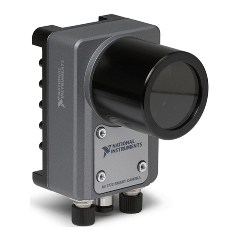
National Instruments NI 177 Series User manual

NI Vision
NI 177x Smart Camera User Manual
September 2011
373491A-01

Support
Worldwide Technical Support and Product Information
ni.com
Worldwide Offices
Visit ni.com/niglobal to access the branch office Web sites, which provide up-to-date contact information,
support phone numbers, email addresses, and current events.
National Instruments Corporate Headquarters
11500 North Mopac Expressway Austin, Texas 78759-3504 USA Tel: 512 683 0100
For further support information, refer to the Technical Support and Professional Services appendix. To comment
on National Instruments documentation, refer to the National Instruments Web site at ni.com/info and enter
the Info Code feedback.
©2011 National Instruments Corporation. All rights reserved.

Important Information
Warranty
NI 177x Smart Cameras are warranted against defects in materials and workmanship for a period of one year from the date of shipment, as
evidenced by receipts or other documentation. National Instruments will, at its option, repair or replace equipment that proves to be defective
during the warranty period. This warranty includes parts and labor.
The media on which you receive National Instruments software are warranted not to fail to execute programming instructions, due to defects in
materials and workmanship, for a period of 90 days from date of shipment, as evidenced by receipts or other documentation. National Instruments
will, at its option, repair or replace software media that do not execute programming instructions if National Instruments receives notice of such defects
during the warranty period. National Instruments does not warrant that the operation of the software shall be uninterrupted or error free.
A Return Material Authorization (RMA) number must be obtained from the factory and clearly marked on the outside of the package before any
equipment will be accepted for warranty work. National Instruments will pay the shipping costs of returning to the owner parts which are covered by
warranty.
National Instruments believes that the information in this document is accurate. The document has been carefully reviewed for technical accuracy. In
the event that technical or typographical errors exist, National Instruments reserves the right to make changes to subsequent editions of this document
without prior notice to holders of this edition. The reader should consult National Instruments if errors are suspected. In no event shall National
Instruments be liable for any damages arising out of or related to this document or the information contained in it.
EXCEPT AS SPECIFIED HEREIN, NATIONAL INSTRUMENTS MAKES NO WARRANTIES, EXPRESS OR IMPLIED, AND SPECIFICALLY DISCLAIMS ANY WARRANTY OF
MERCHANTABILITY OR FITNESS FOR APARTICULAR PURPOSE. CUSTOMER’SRIGHT TO RECOVER DAMAGES CAUSED BY FAULT OR NEGLIGENCE ON THE PART OF NATIONAL
INSTRUMENTS SHALL BE LIMITED TO THE AMOUNT THERETOFORE PAID BY THE CUSTOMER. NATIONAL INSTRUMENTS WILL NOT BE LIABLE FOR DAMAGES RESULTING
FROM LOSS OF DATA, PROFITS, USE OF PRODUCTS, OR INCIDENTAL OR CONSEQUENTIAL DAMAGES, EVEN IF ADVISED OF THE POSSIBILITY THEREOF. This limitation of
the liability of National Instruments will apply regardless of the form of action, whether in contract or tort, including negligence. Any action against
National Instruments must be brought within one year after the cause of action accrues. National Instruments shall not be liable for any delay in
performance due to causes beyond its reasonable control. The warranty provided herein does not cover damages, defects, malfunctions, or service
failures caused by owner’s failure to follow the National Instruments installation, operation, or maintenance instructions; owner’s modification of the
product; owner’s abuse, misuse, or negligent acts; and power failure or surges, fire, flood, accident, actions of third parties, or other events outside
reasonable control.
Copyright
Under the copyright laws, this publication may not be reproduced or transmitted in any form, electronic or mechanical, including photocopying,
recording, storing in an information retrieval system, or translating, in whole or in part, without the prior written consent of National
Instruments Corporation.
National Instruments respects the intellectual property of others, and we ask our users to do the same. NI software is protected by copyright and other
intellectual property laws. Where NI software may be used to reproduce software or other materials belonging to others, you may use NI software only
to reproduce materials that you may reproduce in accordance with the terms of any applicable license or other legal restriction.
Trademarks
LabVIEW, National Instruments, NI, ni.com, the National Instruments corporate logo, and the Eagle logo are trademarks of National
Instruments Corporation. Refer to the Trademark Information at ni.com/trademarks for other National Instruments trademarks.
Other product and company names mentioned herein are trademarks or trade names of their respective companies.
Members of the National Instruments Alliance Partner Program are business entities independent from National Instruments and have no agency,
partnership, or joint-venture relationship with National Instruments.
Patents
For patents covering National Instruments products/technology, refer to the appropriate location: Help»Patents in your software,
the patents.txt file on your media, or the National Instruments Patent Notice at ni.com/patents.
Export Compliance Information
Refer to the Export Compliance Information at ni.com/legal/export-compliance for the National Instruments global trade compliance
policy and how to obtain relevant HTS codes, ECCNs, and other import/export data.
WARNING REGARDING USE OF NATIONAL INSTRUMENTS PRODUCTS
(1) NATIONAL INSTRUMENTS PRODUCTS ARE NOT DESIGNED WITH COMPONENTS AND TESTING FOR A LEVEL OF
RELIABILITY SUITABLE FOR USE IN OR IN CONNECTION WITH SURGICAL IMPLANTS OR AS CRITICAL COMPONENTS IN
ANY LIFE SUPPORT SYSTEMS WHOSE FAILURE TO PERFORM CAN REASONABLY BE EXPECTED TO CAUSE SIGNIFICANT
INJURY TO A HUMAN.
(2) IN ANY APPLICATION, INCLUDING THE ABOVE, RELIABILITY OF OPERATION OF THE SOFTWARE PRODUCTS CAN BE
IMPAIRED BY ADVERSE FACTORS, INCLUDING BUT NOT LIMITED TO FLUCTUATIONS IN ELECTRICAL POWER SUPPLY,
COMPUTER HARDWARE MALFUNCTIONS, COMPUTER OPERATING SYSTEM SOFTWARE FITNESS, FITNESS OF COMPILERS
AND DEVELOPMENT SOFTWARE USED TO DEVELOP AN APPLICATION, INSTALLATION ERRORS, SOFTWARE AND HARDWARE
COMPATIBILITY PROBLEMS, MALFUNCTIONS OR FAILURES OF ELECTRONIC MONITORING OR CONTROL DEVICES,
TRANSIENT FAILURES OF ELECTRONIC SYSTEMS (HARDWARE AND/OR SOFTWARE), UNANTICIPATED USES OR MISUSES, OR
ERRORS ON THE PART OF THE USER OR APPLICATIONS DESIGNER (ADVERSE FACTORS SUCH AS THESE ARE HEREAFTER
COLLECTIVELY TERMED “SYSTEM FAILURES”). ANY APPLICATION WHERE A SYSTEM FAILURE WOULD CREATE A RISK OF
HARM TO PROPERTY OR PERSONS (INCLUDING THE RISK OF BODILY INJURY AND DEATH) SHOULD NOT BE RELIANT SOLELY
UPON ONE FORM OF ELECTRONIC SYSTEM DUE TO THE RISK OF SYSTEM FAILURE. TO AVOID DAMAGE, INJURY, OR DEATH,
THE USER OR APPLICATION DESIGNER MUST TAKE REASONABLY PRUDENT STEPS TO PROTECT AGAINST SYSTEM FAILURES,
INCLUDING BUT NOT LIMITED TO BACK-UP OR SHUT DOWN MECHANISMS. BECAUSE EACH END-USER SYSTEM IS
CUSTOMIZED AND DIFFERS FROM NATIONAL INSTRUMENTS' TESTING PLATFORMS AND BECAUSE A USER OR APPLICATION
DESIGNER MAY USE NATIONAL INSTRUMENTS PRODUCTS IN COMBINATION WITH OTHER PRODUCTS IN A MANNER NOT
EVALUATED OR CONTEMPLATED BY NATIONAL INSTRUMENTS, THE USER OR APPLICATION DESIGNER IS ULTIMATELY
RESPONSIBLE FOR VERIFYING AND VALIDATING THE SUITABILITY OF NATIONAL INSTRUMENTS PRODUCTS WHENEVER
NATIONAL INSTRUMENTS PRODUCTS ARE INCORPORATED IN A SYSTEM OR APPLICATION, INCLUDING, WITHOUT
LIMITATION, THE APPROPRIATE DESIGN, PROCESS AND SAFETY LEVEL OF SUCH SYSTEM OR APPLICATION.
Compliance
Electromagnetic Compatibility Information
This product was tested and complies with the regulatory requirements and limits for electromagnetic compatibility (EMC) as
stated in the product specifications. These requirements and limits are designed to provide reasonable protection against harmful
interference when the product is operated in its intended operational electromagnetic environment.
This product is intended for use in industrial locations. There is no guarantee that harmful interference will not occur in a
particular installation, when the product is connected to a test object, or if the product is used in residential areas. To minimize
the potential for the product to cause interference to radio and television reception or to experience unacceptable performance
degradation, install and use this product in strict accordance with the instructions in the product documentation.
Furthermore, any changes or modifications to the product not expressly approved by National Instruments could void your
authority to operate it under your local regulatory rules.

©National Instruments Corporation v NI 177x Smart Camera User Manual
Contents
About This Manual
Conventions ...................................................................................................................ix
Related Documentation..................................................................................................x
Hardware Documents ......................................................................................x
NI Vision Builder for Automated Inspection Documents...............................x
LabVIEW and NI Vision Development Module Documents..........................xi
NI Vision Acquisition Software Documents...................................................xi
PART I
Getting Started with the NI 177x Smart Camera
Chapter 1
Hardware Overview and Installation
Hardware Overview.......................................................................................................1-2
Connect the Power Supply and I/O................................................................................1-3
Connect to the Development Computer.........................................................................1-5
Direct Connection............................................................................................1-5
Network Connection........................................................................................1-5
Subnet Considerations.......................................................................1-6
IP Address Assignment.....................................................................1-6
Firewall Configuration ....................................................................................1-7
Chapter 2
Software Overview
Configuring the NI Smart Camera with Vision Builder AI...........................................2-2
Configure the IP Address ................................................................................2-2
Install Software on the NI Smart Camera........................................................2-3
Acquire an Image with Vision Builder AI ......................................................2-3
Configuring the NI Smart Camera with LabVIEW .......................................................2-4
Configure the IP Address ................................................................................2-5
Install Software on the NI Smart Camera........................................................2-6
Acquire an Image ............................................................................................2-6

Contents
NI 177x Smart Camera User Manual vi ni.com
PART II
NI 177x Smart Camera Technical Reference
Chapter 3
Connectors
I/O Connector ................................................................................................................ 3-2
NI Smart Camera Power Requirements ........................................................................ 3-4
100/1G Connector ......................................................................................................... 3-4
VGA/USB Connector.................................................................................................... 3-5
Chapter 4
Connecting Lighting and External Devices
Connecting Lighting Devices........................................................................................ 4-1
Connecting a Light Controller ........................................................................ 4-1
Open Collector Outputs................................................................................................. 4-3
Connecting to a NPN Device .......................................................................... 4-3
Connecting to a PNP Device........................................................................... 4-4
Protecting Against Inductive Loads................................................................ 4-4
Connecting to a Triggering Device ............................................................................... 4-6
Connecting to Serial Devices ........................................................................................ 4-7
Chapter 5
Image Sensor
Field of View................................................................................................................. 5-1
Image Sensor Spectral Response................................................................................... 5-3
Gain ............................................................................................................................... 5-3
Auto White Level (NI 177xC Smart Cameras)............................................... 5-4
Black Level (NI 177xC Smart Cameras)....................................................................... 5-5
Look-Up Table .............................................................................................................. 5-5
Maintenance .................................................................................................................. 5-6
Chapter 6
Image Acquisition
Exposure ........................................................................................................................6-1
Acquiring Images .......................................................................................................... 6-2
Internal Timing ............................................................................................... 6-2
External Trigger .............................................................................................. 6-3
Maximum Frame Rate................................................................................................... 6-5
Determining the Maximum Frame Rate ......................................................... 6-5
Determining the Exposure Time ..................................................................... 6-6

Contents
©National Instruments Corporation vii NI 177x Smart Camera User Manual
Determining the Trigger Delay .......................................................................6-6
Calculating the Minimum Frame Period .........................................................6-6
Chapter 7
LED Indicators
Understanding the LED Indicators ................................................................................7-1
Device Initialization ........................................................................................7-2
Power Indicator ...............................................................................................7-2
Status Indicator................................................................................................7-2
User Indicator ..................................................................................................7-3
100/1G Indicator..............................................................................................7-4
Chapter 8
Mounting Information
Appendix A
Specifications
Appendix B
Camera Attributes
Appendix C
Accessories
Appendix D
Technical Support and Professional Services
Glossary
Index

©National Instruments Corporation ix NI 177x Smart Camera User Manual
About This Manual
This manual contains detailed installation instructions and electrical and
mechanical information for the National Instruments 177x Smart Camera.
Conventions
The following conventions appear in this manual:
»The »symbol leads you through nested menu items and dialog box options
to a final action. The sequence Options»Settings»General directs you to
pull down the Options menu, select the Settings item, and select General
from the last dialog box.
This icon denotes a note, which alerts you to important information.
This icon denotes a caution, which advises you of precautions to take to
avoid injury, data loss, or a system crash.
When this symbol is marked on a product, it denotes a warning advising
you to take precautions to avoid electrical shock.
bold Bold text denotes items that you must select or click in the software, such
as menu items and dialog box options. Bold text also denotes parameter
names.
italic Italic text denotes variables, emphasis, a cross-reference, or an introduction
to a key concept. Italic text also denotes text that is a placeholder for a word
or value that you must supply.
monospace Text in this font denotes text or characters that you should enter from the
keyboard, sections of code, programming examples, and syntax examples.
This font is also used for the proper names of disk drives, paths, directories,
programs, subprograms, subroutines, device names, functions, operations,
variables, filenames, and extensions.
monospace italic
Italic text in this font denotes text that is a placeholder for a word or value
that you must supply.

About This Manual
NI 177x Smart Camera User Manual x ni.com
Related Documentation
The following documents contain information that you may find helpful as
you read this manual:
Hardware Documents
•NI 177x Series Smart Camera: Using the NI Smart Camera with
LabVIEW—Contains basic installation and configuration instructions
for using the NI Smart Camera with LabVIEW.
•NI 177x Series Smart Camera: Using the NI Smart Camera with Vision
Builder AI—Contains basic installation and configuration instructions
for using the NI Smart Camera with Vision Builder AI.
•Power and I/O Accessory for NI 177x Smart Cameras User
Guide—Contains installation and operation instructions, and feature
descriptions for the power and I/O accessory (781993-01).
• NI Developer Zone—Contains example programs, tutorials, technical
presentations, the Instrument Driver Network, a measurement
glossary, an online magazine, a product advisor, and a community area
where you can share ideas, questions, and source code with developers
around the world. The NI Developer Zone is located on the
National Instruments Web site at ni.com/zone.
NI Vision Builder for Automated Inspection Documents
•NI Vision Builder for Automated Inspection Tutorial—Describes
Vision Builder for Automated Inspection and provides step-by-step
instructions for solving common visual inspection tasks, such as
inspection, gauging, part presence, guidance, and counting.
•NI Vision Builder for Automated Inspection: Configuration
Help—Contains information about using the Vision Builder for
Automated Inspection Configuration Interface to create a machine
vision application.
•NI Vision Builder for Automated Inspection: Inspection
Help—Contains information about running applications created with
Vision Builder for Automated Inspection in the Vision Builder
Automated Inspection Interface.

About This Manual
©National Instruments Corporation xi NI 177x Smart Camera User Manual
LabVIEW and NI Vision Development Module Documents
•LabVIEW Help—Includes information about LabVIEW programming
concepts, step-by-step instructions for using LabVIEW, and reference
information about LabVIEW VIs, functions, palettes, menus, and
tools.
•Getting Started with LabVIEW—Use this manual as a tutorial to
familiarize yourself with the LabVIEW graphical programming
environment and the basic LabVIEW features you use to build data
acquisition and instrument control applications.
•Getting Started with the LabVIEW Real-Time Module—Use this
manual as a tutorial to familiarize yourself with the LabVIEW
Real-Time Module and the basic Real-Time Module features you use
to build real-time applications.
•NI Vision Concepts Help—Describes the basic concepts of image
analysis, image processing, and machine vision. This document also
contains in-depth discussions about imaging functions for advanced
users.
•NI Vision for LabVIEW Help—Describes how to create machine
vision and image processing applications in LabVIEW using the
Vision Development Module. The help file guides you through
tasks beginning with setting up your imaging system to taking
measurements. It also describes how to create a real-time vision
application using NI Vision with the LabVIEW Real-Time Module
and contains reference information about NI Vision for LabVIEW
palettes and VIs.
NI Vision Acquisition Software Documents
•NI-IMAQdx VI Reference Help—Contains reference information
about the LabVIEW VIs and properties for NI-IMAQdx driver
software.
•
Measurement & Automation Explorer Help for NI-IMAQdx
—Describes
how to configure NI-IMAQdx driver software, NI image acquisition
devices, and NI Smart Cameras using Measurement & Automation
Explorer.

©National Instruments Corporation I-1 NI 177x Smart Camera User Manual
Part I
Getting Started with the NI 177x Smart
Camera
This section provides the following information:
• Basic information about the NI 177x Smart Camera hardware
• Instructions for configuring the NI 177x Smart Camera hardware
• Basic information about software options for application development
• Instructions for acquiring your first image with the NI 177x Smart
Camera using the selected application development software

©National Instruments Corporation 1-1 NI 177x Smart Camera User Manual
1
Hardware Overview and
Installation
This chapter provides an overview of the features and components of the
NI 177x Smart Camera. Figure 1-1 shows the NI 177x Smart Camera.
Figure 1-1. NI 177x Smart Camera
1 Image Sensor
2 C-Mount
3 Lens Cover Mount
4 LED Indicators
5 I/O Connector
6 100/1G Connector
7 VGA/USB Connector
I/O 100/1G
Power
Status
User
VGA/
USB
100/
1G
NATIONAL
INSTRUMENTS
NI 177X SMART CAMERA
1
3
2
765
4

Chapter 1 Hardware Overview and Installation
NI 177x Smart Camera User Manual 1-2 ni.com
Hardware Overview
NI 177x Smart Cameras incorporate an Intel®Atom™Z530 (1.60 GHz)
processor, image sensor, and digital I/O M12 connectors in a compact,
rugged, IP67 rated housing. Refer to the I/O Connector section of
Chapter 3, Connectors, for more information about the digital I/O
capabilities of the device.
NI 177x Smart Cameras are available with the following image sensor
configurations.
For more information about the image sensors, refer to Chapter 5, Image
Sensor. For complete device specifications, refer to Appendix A,
Specifications.
NI 177x Smart Cameras use a standard C-mount lens, and include
4 opto-coupled inputs, 4 open collector outputs, an optically isolated
trigger input, and a constant current output for connecting to external
devices. For complete device specifications, refer to Appendix A,
Specifications.
NI 177x Smart Cameras includes 4 LED indicators for communicating
system status. Refer to Chapter 7, LED Indicators, for more information
about the LED indicators.
Table 1-1. NI 177x Smart Camera Models
Model Resolution
Color
Support
NI 1772 640 × 480 pixels (VGA) No
NI 1774 1,280 × 960 pixels (SXGA) No
NI 1776 1,600 × 1,200 pixels (UXGA) No
NI 1778 2,448 × 2,050 pixels (5 MP) No
NI 1772C 640 × 480 pixels (VGA) Yes
NI 1774C 1,280 × 960 pixels (SXGA) Yes
NI 1776C 1,600 × 1,200 pixels (UXGA) Yes

Chapter 1 Hardware Overview and Installation
©National Instruments Corporation 1-3 NI 177x Smart Camera User Manual
Connect the Power Supply and I/O
National Instruments provides the following two cable options for
connecting a power supply (782032-01) and I/O to the NI 177x Smart
Camera.
•Power and I/O Accessory (781993-01)—A terminal block that
simplifies power and I/O signal configuration for the NI 177x Smart
Camera. The accessory uses a 25-pin D-SUB connector and a 17-pin
M12 to 25-pin D-SUB cable.
•17-pin M12 Pigtail Cable (153131-03)—An open-ended cable that
you can use to create your own custom cable. Refer to the I/O
Connector section of Chapter 3, Connectors for wiring information.
Caution Use the NI 177x Smart Camera only with a 12 W, 24 VDC ±10%, UL listed,
limited power source (LPS) supply. The power supply will bear the UL listed mark, LPS.
The power supply must also meet any safety and compliance requirements for the country
of use.
To connect a power supply to the NI 177x Smart Camera using the Power
and I/O Accessory for NI 177x Smart Cameras, refer to Figure 1-2 and
complete the following steps.

Chapter 1 Hardware Overview and Installation
NI 177x Smart Camera User Manual 1-4 ni.com
Figure 1-2. Connecting the NI 177x Smart Camera to the Power and I/O Accessory
1. Connect and secure the 17-pin M12 connector on the I/O cable to the
I/O connector on the NI 177x Smart Camera.
2. Connect and secure the 25-pin D-SUB connector on the I/O cable to
the CAMERA connector on the terminal block.
3. Connect the power supply output to the 24 V in connector on the
terminal block.
4. Connect any additional I/O signals necessary for your application to
the appropriate terminal block connector. Refer to the I/O Connector
section of Chapter 3, Connectors, for pin information.
5. Plug the power supply into an outlet.
When power is first applied to the device, the Power and Status LED
indicators flash red once while internal systems power up. The Power LED
then lights green if power is wired correctly.

Chapter 1 Hardware Overview and Installation
©National Instruments Corporation 1-5 NI 177x Smart Camera User Manual
Connect to the Development Computer
The NI 177x Smart Camera can connect to the development computer
directly or through a network. To configure the NI 177x Smart Camera
through a network, the NI 177x Smart Camera and the development
computer must be connected to the same subnet.
Caution To prevent data loss and to maintain the integrity of your Ethernet installation, do
not use a cable longer than 100 m. National Instruments recommends using a shielded
twisted pair cable for maximum signal integrity.
Direct Connection
To connect the NI 177x Smart Camera directly to the development
computer, complete the following steps.
1. Connect the 8-pin female M12 connector to the 100/1G connector on
the NI 177x Smart Camera.
2. Connect the Ethernet connector to an Ethernet port on the development
computer.
The NI 177x Smart Camera is now connected directly to the development
computer.
Network Connection
To connect the NI 177x Smart Camera to the development computer
through a network, complete the following steps.
1. Verify that the development computer is connected to the network and
powered on.
2. Connect the 8-pin female M12 connector to the 100/1G connector on
the NI 177x Smart Camera.
3. Connect the Ethernet connector to an Ethernet port.
The NI 177x Smart Camera is now connected through a network and is
available for additional configuration with the development computer.

Chapter 1 Hardware Overview and Installation
NI 177x Smart Camera User Manual 1-6 ni.com
Subnet Considerations
To use the NI 177x Smart Camera on a subnet other than the one on which
the development computer resides, first connect and configure the NI 177x
Smart Camera on the same subnet as the development computer. Next,
physically move the NI 177x Smart Camera. Contact your network
administrator for assistance in determining which network ports reside on
the same subnet.
IP Address Assignment
If the NI 177x Smart Camera is connected directly to the development
computer, the device will use a link-local IP address. If the NI 177x Smart
Camera is connected to a network that has a DHCP server, the device will
automatically obtain an IP address. You can also configure the NI 177x
Smart Camera to use a static IP address. If you cannot locate the NI 177x
Smart Camera on the network, first refer to the Firewall Configuration
section, then assign a static IP address or contact your network
administrator.
Note If the NI 177x Smart Camera IP address is 169.254.x.x, the device is only accessible
from the local subnet. To access the smart camera from a remote subnet, configure the
smart camera to obtain an IP address from a DHCP server or manually assign a static
IP address.
DHCP IP Addresses
Using a DHCP server to assign an IP address has the following advantages:
• The DHCP server manages the IP addresses of the network. You do not
need to know the IP address of the NI 177x Smart Camera.
• The DHCP server does not allow other devices to use the IP address
that is already assigned to your NI 177x Smart Camera.
Although using a DHCP server simplifies IP address configuration, using a
static IP address can be more reliable. Consider the following potential
issues before using a DHCP server to assign an IP address to the NI 177x
Smart Camera:
• If the network has both static IP addresses and IP addresses managed
by a DHCP server, the DHCP server must be configured to not use
reserved static IP addresses. If the DHCP server is not configured this
way, the DHCP server can assign a reserved IP address to another
device, causing address conflicts on the network, which results in some
devices being unreachable.

Chapter 1 Hardware Overview and Installation
©National Instruments Corporation 1-7 NI 177x Smart Camera User Manual
When a NI 177x Smart Camera configured for DHCP starts, it must be able
to connect to the DHCP server. If the NI 177x Smart Camera cannot
connect to the DHCP server and is not connected to the same subnet as the
development computer, it does not appear in MAX or Vision Builder AI.
Note A NI 177x Smart Camera connected directly to the development computer or to the
same subnet as the development computer is always configurable from MAX or Vision
Builder AI, regardless of the IP address settings.
Firewall Configuration
If you are having difficulty detecting the NI 177x Smart Camera on your
network, you must configure the firewall to open the TCP/UDP ports used
by the NI 177x Smart Camera and the host machine. The required ports are
listed in Table 1-2.
If your firewall is controlled remotely or you are unsure about configuring
the firewall, contact your network administrator.
Table 1-2. TCP/UDP Ports Used by the NI 177x Smart Camera
Port Type Details
3580 TCP/UDP Reserved as nati-svrloc (NAT-ServiceLocator). Used by Measurement &
Automation Explorer (MAX) to locate remote targets.
7749 TCP Used for remote image display (not reserved).
7750 TCP Used for NI-IMAQdx remote configuration (not reserved).
3363 TCP/UDP Reserved as nati-vi-server (NATI VI Server). Used by Vision Builder for
Automated Inspection to configure a remote NI Smart Camera.

©National Instruments Corporation 2-1 NI 177x Smart Camera User Manual
2
Software Overview
National Instruments provides two options for developing applications for
the NI 177x Smart Camera.
Note Vision Builder for Automated Inspection and NI Vision Acquisition Software are
included with the NI 177x Smart Camera. LabVIEW, the LabVIEW Real-Time Module,
and the NI Vision Development Module are sold separately.
The following sections describe the installation and configuration process
for each development environment:
• Refer to Configuring the NI Smart Camera with Vision Builder AI for
information about using the NI 177x Smart Camera with Vision
Builder AI.
• Refer to Configuring the NI Smart Camera with LabVIEW for
information about using the NI 177x Smart Camera with LabVIEW.
The installation and configuration process for each development
environment is different. Complete only the instructions for your chosen
development environment.
Caution National Instruments software may require you to update the firmware for this
device. Do not remove power from the device until the software indicates that the firmware
update is complete. Removing power during a firmware update could cause your device to
become unusable.
Vision Builder
for
Automated Inspection
LabVIEW
LabVIEW Real-Time Module
NI Vision Development Module
NI Vision Acquisition Software
or

Chapter 2 Software Overview
NI 177x Smart Camera User Manual 2-2 ni.com
Configuring the NI Smart Camera with Vision Builder AI
Vision Builder AI is interactive, menu-driven configuration software for
developing, benchmarking, and deploying machine vision applications.
With Vision Builder AI, you can perform powerful visual inspection tasks
and make decisions based on the results of individual tasks. You can also
migrate your inspection to LabVIEW to extend the capabilities of your
application, if necessary. The latest version of Vision Builder AI is
included with the NI 177x Smart Camera.
Complete the following steps to install Vision Builder AI and configure the
NI 177x Smart Camera.
1. Install and activate Vision Builder AI on the development computer.
Refer to the NI Vision Builder for Automated Inspection Readme for
installation instructions.
2. Launch Vision Builder AI.
3. On the Vision Builder AI welcome screen, select the NI 177x Smart
Camera in the list of targets.
If the NI 177x Smart Camera does not appear in the list of targets,
verify that the device has power and is connected to an Ethernet port
on the same subnet as the development computer, then click Refresh
Target List. Refer to Chapter 7, LED Indicators for information about
LED status messages.
4. Click Install Software. The Remote Target Configuration Wizard
launches in a new window.
5. In the Name field, enter a name for the device. Use the Description
field to enter any additional information or a brief description of the
device.
Device names are limited to 31 characters with no spaces or special
characters, except hyphens. The first and last characters must be
alphanumeric.
6. Click Next.
Configure the IP Address
Complete the following steps to configure IP address settings for the
NI 177x Smart Camera in the The Remote Target Configuration Wizard.
1. If the network is configured to issue IP addresses using DHCP, select
Obtain IP address from DHCP server. Otherwise, configure the
IP address manually by selecting Edit the IP settings and clicking
Suggest Values.
This manual suits for next models
7
Table of contents
Other National Instruments Digital Camera manuals

National Instruments
National Instruments Vision 177 Series User manual

National Instruments
National Instruments NI 1712 User manual

National Instruments
National Instruments ISC-1772 User manual

National Instruments
National Instruments ISC-1780 User manual

National Instruments
National Instruments NI ISC-1772C User manual

National Instruments
National Instruments NI 17 xx User manual

National Instruments
National Instruments NI 17xx Smart User manual

National Instruments
National Instruments 177 Series User manual

National Instruments
National Instruments NI Vision 17 Series User manual

National Instruments
National Instruments NI Vision NI 17xx User manual