WARNING
CONTENTS
(Page) (Page)
- 2 -
PRECAUTIONS TO BE OBSERVED BEFORE AND
DURING SERVICING TO AVOID POSSIBLE EXPOSURE
TO EXCESSIVE MICROWAVE ENERGY
(A) Do not operate or allow the oven to be operated with the
door open.
(B) Make the following safety checks on all ovens to be serviced
before activating the magnetron or other microwave source,
and make repairs as necessary:
(1) Interlock operation
(2) Proper door closing
(3) Seal and sealing surfaces (arcing, wear, and other
damage)
(4) Damage to or loosening of hinges and latches.
(5) Evidence of dropping or abuse
(C) Before turning on microwave power for any service test or
inspection within the microwave generating compartments,
check the magnetron, waveguide or transmission line, and
cavity for proper alignment, integrity and connections.
(D) Any defective or misadjusted components in the interlock,
monitor, door seal, and microwave generation and trans-
mission systems shall be repaired, replaced, or adjusted
by procedures described in this manual before the oven is
released to the owner.
(E) A microwave leakage check to verify compliance with the
Federal Performance Standard should be performed on
each oven prior to release to the owner.
WARNING
This service information is designed for experienced repair technicians only and is not designed for use by the general public. It does not
contain warnings or cautions to advise non-technical individuals of potential dangers in attempting to service a product.
Products powered by electricity should be serviced or repaired only by experienced professional technicians. Any attempt to service or repair
the product or products dealt with in this service information by anyone else could result in serious injury or death.
1.This product should be serviced only by trained, qualified personnel.
2.Check for radiation leakage before and after every servicing according to the “procedure for measuring radiation leakage.”
3.If the unit cannot be repaired on site, advise the customer not to use until unit is repaired.
4.There are special components used in the microwave oven which are important for safety. These parts are marked with
a on the replacement parts list. It is essential that these critical parts should be replaced only with the manufacture’s
specified parts to prevent microwave leakage, shock, fire, or other hazards. Do not modify the orginal design.
This service manual covers products for following markets.
When troubleshooting or replacing parts, please refer to the country/area identifications shown below for your
applicable product specification.
HNE ......................................... For Hong Kong KKE .................................... For UAE, Egypt, Iran
YNQ ......................................... For Singapore KNQ ................................... For Kuwait, Doha, Quatar
MNQ ......................................... For Malaysia Oman, Bahrain, Pakistan
TNE .......................................... For Thailand, Indonesia SNM ................................... For Saudi Arabia
YKE .......................................... For Others ZPE .................................... For CIS Countries
WNT ......................................... For Tai Wan
FEATURE CHART ............................................................................... 4
CONTROL PANEL ............................................................................... 4
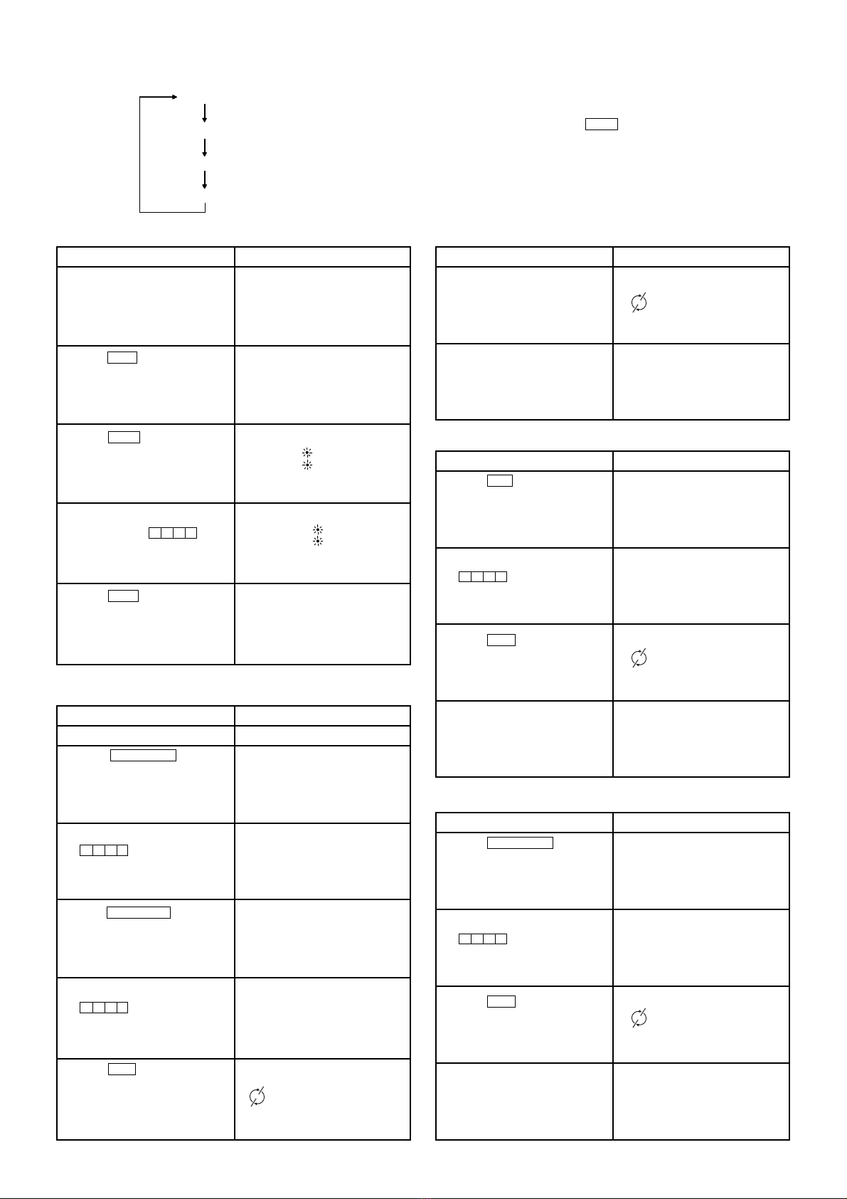
OPERATION AND DIGITAL PROGRAMMER
CIRCUIT TEST PROCEDURE ............................................................ 5
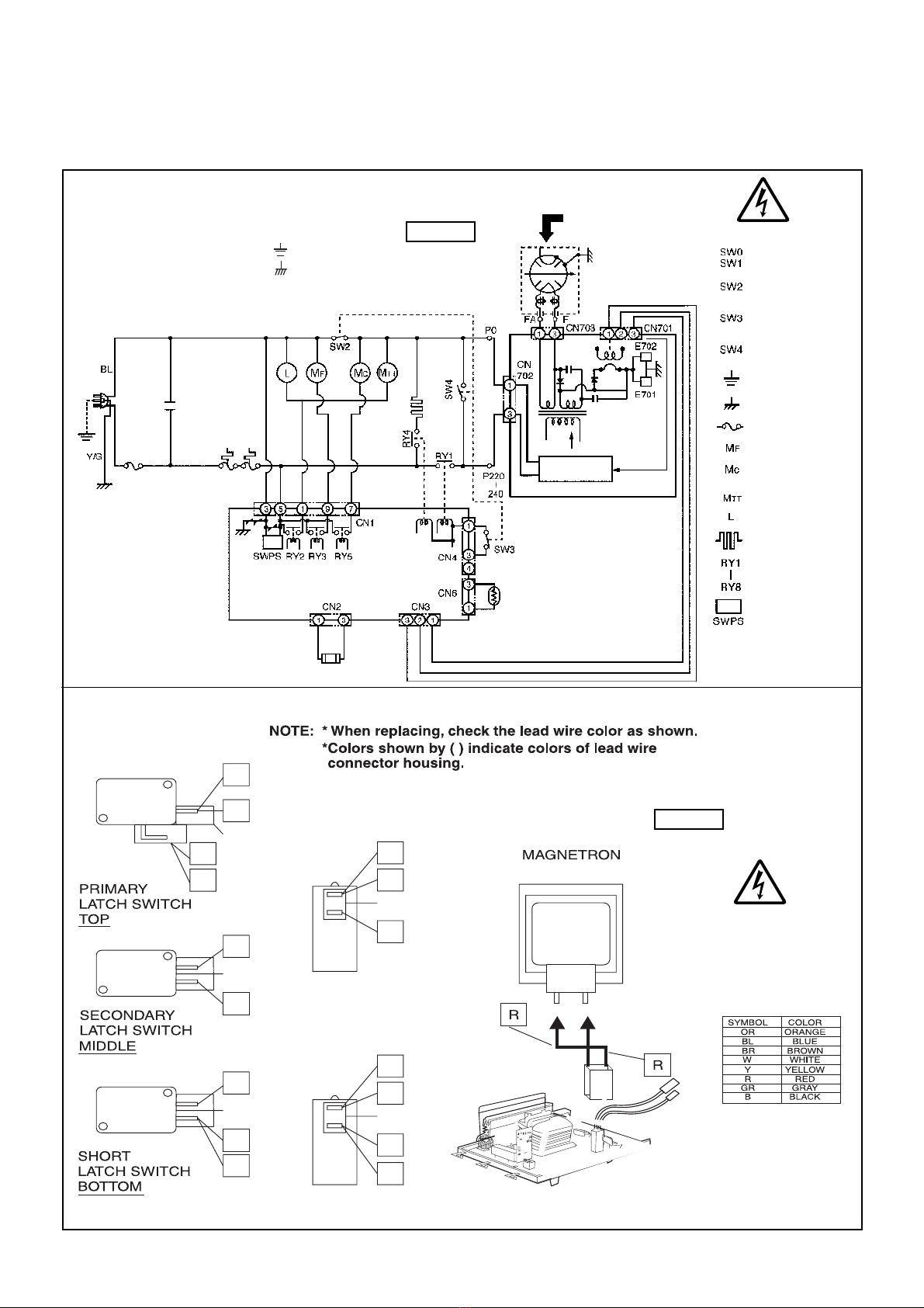
SCHEMATIC DIAGRAMS .................................................................... 7
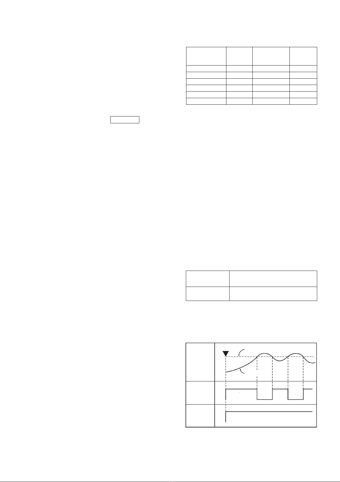
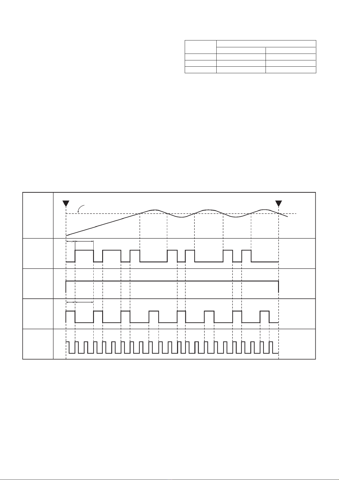
DESCRIPTION OF OPERATING SEQUENCE ................................... 9
CAUTIONS TO BE OBSERVED WHEN TROUBLESHOOTING ......... 11
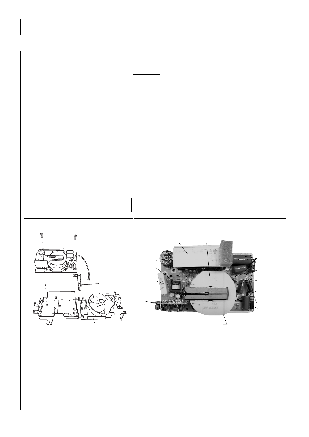
DISASSEMBLY AND PARTS REPLACEMENT PROCEDURE ........... 13
COMPONENT TEST PROCEDURE .................................................... 17
MEASUREMENTS AND ADJUSTMENTS ........................................... 20
PROCEDURE FOR MEASURING MICROWAVE ENERGY LEAKAGE ...
21
TROUBLESHOOTING GUIDE ............................................................ 22
EXPLODED VIEW AND PARTS LIST .................................................. 28
SCHEMATIC DIAGRAM &
PARTS LIST OF DIGITAL PROGRAMMER CIRCUIT ......................... 34
!
!


M Service manual")


