Neilsen CT3823 User manual

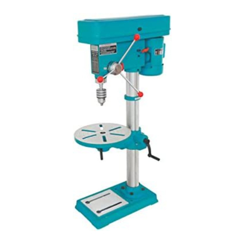
13MM BENCH DRILL CT3823
、
INSTRUCTION MANUAL
Read the operating instructions carefully before using the tool and observe
the safety instructions. Keep the operating instructions in a safe place.
Cannon Tools Limited
Address:20 Station Road, Rowley Regis, West Midlands, B65 0JU.UNITED KINGDOM

1
EC DECLARATION OF CONFORMITY
We CANNON TOOLS LTD
20 Station road, Rowley Regis, West Midlands,B65 0JU.U.K.
Declare that the following machine complies with the appropriate basic safety
and health requirements of the EC Directive based on its design and type, as
brought into circulation by us.
In case of alteration of the machine, not agreed upon by us, this declaration
will lose its validity.
Product description: BENCH DRILL
Model: CT3823
Applicable EC Directives:
EC Low Voltage Directive 2014/35/EU
EC Machinery Directive 2006/42/EU
EC Directive of Electromagnetic Compatibility 2014/30/EU
Harmonized standards
EN 62841-1:2015, EN ISO 12100:2010, EN 61000-6-3:2007+A1:2011,
EN 61000-6-1:2007, EN 61000-3-2:2014, EN 61000-3-3:2013,
EN 60204-1:2006+A1:2009
20 Station Road, Rowley Regis, West Midlands, B65 0JU.U.K.
Mr. Gurcharan Tony Singh Sanghera
Managing Director
CANNON TOOLS LTD
2016-5-11

2
1. SPECIFICATIONS
Model CT3823
Voltage 230V~
Frequency 50Hz
Power 350W
Spindle speed 5 speed
Motor no-load speed 1400/min
Chuck 1.5-13mm
Spindle taper B16
Max. Drilling depth 50mm
Table size 160x160mm
Table tilting range 0
o
-45
o
Base size 290x190mm
Column diameter 46mm
Distance spindle to column 104mm
Distance spindle to table 200mm
Distance spindle to base 290mm
Overall height 580mm
2. IMPORTANT SAFETY INFORMATION
WARNING! For your own safety, read this manual and the general safety
instructions carefully before using the appliance. Your power tool should only
be given to other users together with these instructions.
General Safety Instructions
WARNING
For your Own Safety Read Instructions Manual Before Operating Drill Press
1. Wear eye protection.
2. Do not wear gloves, necktie, or loose clothing.
3. Clamp workpiece or brace against column to prevent rotation.
4. Use recommended speed for drill accessory, and workpiece material.

3
5. KEEP GUARDS IN PLACE and in working order.
6. REMOVE ADJUSTNG KEYS AND WRENCHES. From habit of checking to
see that keys and adjusting wrenches are removed from tool before turning it
on.
7. KEEP WORK AREA CLEAN. Cluttered areas and benches invite accidents.
8. DON'T USE IN DANGEROUS ENVIRONMENT. Don' t use power tools in
damp or wet locations, or expose them to rain. Keep work area well lighted.
9. KEEP CHILDREN AWAY. All visitors should be kept safe distance from work
area.
10. MAKE WORKSHOP KID PROOF with padlocks, master switches, or by
removing starter keys.
11. DON'T FORCE TOOL. It will do the job better and safer at the rate for which
was designed.
12. USE RIGHT TOOL. Don' t force tool or attachment to do a job for which it
was not designed .
13. WEAR PROPER APPAREL, No loose clothing, gloves, neckties, rings,
bracelets, or other jewelry to get caught in moving parts. Nonslip footwear is
recommended. Wear protective hair covering to contain long hair.
14. ALWAYS USE SAFETY GLASSES. Also use face or dust mask if cutting
operation is dusty. Everyday eyeglasses only have impact resistant lenses, they
are NOT safety glasses.
15. SECURE WORK. Use clamps or a vise to hold work when practical. It's safer
than using our hand and it frees both hands to operate tools.
16. DON'T OVER REACH. Keep proper footing and balance at all times.
17. MAINTAIN TOOLS WITH CARE. Keep tools sharp and clean for best and
safest performance. Follow instructions for lubricating and changing accessories.
18. DISCONNECT TOOLS before servicing, when changing accessories such
as blades, bits,cutters, etc.
19. REDUCE THE RI SK OF UNINTENTIONAL STARTING. Make sure switch is
in off position before plugging in.
20. USE RECOMMENDED ACCESSORIES. Consult the owner's manual for
recommended accessories. The use of improper accessories may cause risk of
injury to persons.
21. NEVER STAND ON TOOL. Serious injury could occur if the tool is
unintentionally contacted .
22. CHECK DAMAGED PARTS. Before further use of the tools, a guard or other
part that is damaged should be carefully checked to determine that it will operated
properly and perform is intended function - cheek for alignment of moving parts,
binding of moving parts, breakage of parts, and any other conditions that may
affect its operation. A guard or other parts that is damaged
should be properly repaired or replaced before operating this tool.

4
23. DIRECTION OF FEED. Feed work into a blade or cutter against the eirection
of rotation of the blade or cutter .
24. NEVER LEAVE TOOL RUNNING UNATTENDED. TURN POWER OFF.
Don't leave tool until it comes to a complete stop.
Safety Instructions For Drill Press
1. Wear eve protection.
2. Do not wear gloves, necktie, or loose clothing.
3. Clamp workpiece or brace against column to prevent rotation.
4. Use recommended speed tor drill accessory, and workpiece material.
5. Be sure drill bit or cutting tools is securely locked in the chuck.
6. Be sure chuck key is removed from the chuck before turning on power.
7. Adjust the table or depth stop to avoid drilling into the table. Shut off the power
remove the drill bit on cutting tool and clean the table before leaving the
machine.
8. Do not operate until it is completely assembled and installed according to the
instructions.
9. If any part of your drill press in malfunction or has been damaged or broken, do
not operate until the part is properly repaired or replaced.
10. Never place your fingers in a position where they could contact the drill or
other cutting tool if the workpiece should unexpectedly shift.
11. Never use your hand to hole on the object while drilling, always screw the
object tight on the working table or use the drill vise to prevent accident injury.
12. Never perform any operation by moving the head or table with respect to one
another. Do not pull the motor switch “ON” or start any operation before
checking the head and the table lock handles are clamped tight to column,
and head and table support collars are correctly positioned.
13. Before pulling the motor switch "ON" be positive the belt guard is down the
chuck is installed properly.
14. Lock the motor switch when leaving the drill press. Do not perform layout,
assembly or setup work on the table while the cutting tool is rotating.
Voltage Warning
1. Before connecting the tool to a power source (receptacle, outlet, etc. ) Be sure
the voltage supplied is the same as the rating on the tool motor.
2. A power source with voltage greater than that specified for the tool can result in
serious injury to the user.
3. If you're unsure of the voltage rating do not use tool. Also using a power source
with voltage less than that required for the tool will harm the motor.

5
3. UNPACKING & CHECKING
Carefully remove the bench drill from the packaging and examine it for any sign of
damage that may have happened during shipping. Lay the contents out and
check them . If any part is damaged or missing, please contact the seller and do
not attempt to use the power tool.
If any of the packaging is to be thrown away, make sure they are disposed of
correctly, according to local regulations.
1. No-volt on/off switch
11. Motor/belt tension adjuster
2. Depth stop 12. Plunge handle assembly
3. Spindle 13. Geared chuck
4. Pulley cover 14. Work table tilt scale
5. Motor cut-out micro switch 15. Work table tilt locking bolt
6. Motor pulley 16. Work table
7. Spindle pulley
17. Work table height/rotation lock
8. Guard
18. Moulded plug & cable
9. Motor
19. Base
10. Column

6
4. OPERATION INSTRUCTIONS
GROUNDING INSTRUCTIONS
1. In the event of a malfunction or breakdown, grounding provides a path of least
resistance for electric current to reduce the risk of electric shock. This tools is
equipped with an electric cord having an equipment - grounding conductor and
a grounding plug. The plug must be plugged into a matching outlet that is
properly installed and grounded in accordance with all local codes and
ordinances.
2. Do not modify the plug provided, if it will not fit the outlet, have the proper outlet
installed by a qualified electrician.
3. Improper connection of the equipment - grounding conductor can result in a
risk of electric shock. The conductor with insulation having an outer surface that
is green with or without yellow stripes is the equipment - grounding conductor. If
repair or replacement of the electric cord or plug is necessary, do not connect
the equipment - grounding conductor to a live terminal.
4. Check with a qualified electrician or serviceman if the grounding instructions
were not completely understood, or if in doubt as to whether the tools is
properly grounded.
5. Use only 3 - wire extension cords that have 3 - prong grounding plugs and 3 -
pole receptacles that accept the tool's plug.
6. Repair or replace damaged or worn cord immediately.
7.This tool is intended for use on a circuit that has an outlet that looks like the one
illustrated in sketch A , and has a grounding plug that looks like the plug
illustrated in Sketch A, A temporary adapter, which looks like the adapter
illustrated in Sketches B and C may be used to connect this plug to a 2 - pole
receptacle as shown in Sketch B if a properly grounded outlet in not available.
The temporary adapter should be used only until a qualified electrician can
installed a property grounded outlet , the green colored rigid ear, lug, etc.
extending from the adapter must be connected to a permanent ground such as
a properly grounded outlet box.

7
ASSEMBLY
When assembling unit, refer to drawings for part location.
1. Place the base on a flat surface and fasten the column assembly.
2. Slip the table assembly onto the column and slide it down until it rests on the
base.
3. Install the table lock handle onto the table assembly.
4. Position the head assembly on top of the column and secure it in place by
tightening two headless screws.
5. Assemble handles into the feed shaft on the right side of the drill press head.
6. Thoroughly clean the inside of the chuck taper and the spindle taper with a
clean soft cloth and solvent. Insert the chuck onto the spindle. Tap sharply
using a piece of wood to prevent damage to the chuck.
7. Place the belt on the pulley, slide the motor until not the belt is moderately tight.
Tighten the slide bar belt on the drill press head.
8. Be sure the drill press switch is off and the unit plugged in. Rotate the pulleys
by hand to check the alignment.
9. Close the Cover. Plug the cord into a grounded outlet. "JOG" the drill press on
briefly to be sure that all parts are clearing the guards.
TABLE ADJUSTMENTS
1. Height adjustments: To adjust table, hold the table with one hand and loosen
table lock handle. Adjust the table to the desired position and retighten the lock
handle.
2. Tilting worktable: Loosen the pivot bolt. Remove the small locator pin. To do
this,"loosen" the nut until the pin easily slips out. Tilt the table to the desired
angle up to 45
o
and retighten bolt. Reinsert the locator pin when returning the
table to zero degree.
3. Rotation of worktable: Loosen the table (item 7 in assembly diagram). To obtain
more distance between the chuck and the table. The worktable can be rotated
180
o
and the base can be used as a worktable. This will permit the drilling of
larger objects.
INSTALLATION
1. After installing the drill press, use the kerosene to wash out the anti - rust oil
protective coating applied at the factory. Then wipe drill with lubrication oil.
2. Install your drill press in flat, sturdy floor or surface.
a. Check if the drill press in shaking when the motor is switch "ON".
b. Check if the spindle shaft moves smoothly.

8
OPERATION
1. Screw or clamp to piece to the drill table before drilling, This will prevent
injuries and precision workmanship.
2. Insert selected drill bit in the chuck that is located below the spindle shaft.
3. Plug the electric socket to the outlet and press "ON" the switch, then the
spindle shaft will rotate freely.
4. When drilling hold on the handle at the right side of the head frame and press
downward.
5. If the spindle shaft rotates counter clockwise it is probably caused by wrong
connection. Check and change wiring connection.
PRECAUTION
1. In changing the speed you have to turn off the switch and wait until the
machine is completely stop.
2. Take off the chuck key before starting the motor.
3. Never use your hand to hold an object while drilling it, always screw or clamp
the workpiece tight on the drill table or use drill press vise to secure material to
be drill.
4. Keep off your hand from the drill bit while drilling.
5. Wear protective eye goggle when operating.
CHANGING SPEEDS
To change spindle speed, loosen the slide bar bolt, on the right of the head. Slide
the motor toward the front of the drill press and then tighten the slide bar bolt.
This will loosen the belt and permit relocating the belt to the desired pulley for the
required spindle speed. After selection has been made,loosen the slide bar bolt,
slide the motor toward the rear of the drill press and tighten the slide bar bolt
again, check the belt for proper tension and make any final adjustment.
SPINDLE MOTOR 5SPEED
SPEED
1 2 3 4 5
50Hz 610
890
1230
1720
2560

9
6. MAINTENANCE
After using the machine, clean it completely and lubricate all sliding and moving
parts. For your own safety, turn switch "OFF" and remove plug from power source
outlet before maintaining or lubricating your drill press.
7. TROUBLESHOOTING
Warning: For your own safety, turn switch “Off “ or “ O” and always remove
plug from power source outlet before trouble shooting.
Trouble
Probable Cause
Remedy
Noisy operation
1. Incorrect belt tension
2. Dry spindle
3.Loose spindle pulley or motor
pulley
1. Adjust tension
2. Lubricate spindle
3.Tighten set screws in
pulleys
Bit burns or
smokes
1. Incorrect speed
2. Chips not coming out of hole
3. Dull it
4. Feeding too slow
5. Not lubricated
6. Bit running back - wards
1. Change speed
2. Retract bit frequently to
clear chips
3. Sharpen of replace bit
4. Feed fast enough allow
drill to cut.
5. Lubricate bit
6. Check motor rotation
Excessive drill
run - out or
wobble
1. Bent bit
2. Worn spindle bearings
3. Bit not properly installed in
chuck
4. Chuck not properly installed
1. Use a straight bit
2. Replace bearings
3. Install bit properly
4. Install chuck properly
Drill binds in
workpiece
1. Workpiece pinching bit
or excessive feed pressure
2. Improper belt tension
1. Support or re-clamp
workpiece
2. Adjust tension
Work piece tron
loose from hand
1. Not supported or clamp
properly
1. Support of clamp
workpiece
Motor running but
shaft does not
turn
1. Setscrew in trolley works
loose 1. Tighten setscrew
8. DISPOSAL GUIDELINES
At the end of the machine’s working life, or when it can no longer be repaired,
ensure that it is disposed of according to national regulations.
• Contact your local authority for details of collection schemes in your area.
In all circumstances:
• Do not dispose of power tools with domestic waste.

10
• Do not incinerate.
• Do not abandon in the environment.
• Do not dispose of WEEE* as unsorted municipal waste.
9. SYMBOLS
The following symbols are used in this manual and/or on the machine:
Warning
Do not wear loose
clothing
Warning!
Read the instruction
manual
In accordance with
essential safety
standards of
applicable European
directives
Warning!
Do not wear gloves.
Warning!
Wear ear defenders.
Wear googles.
Wear dust mask.
Keep hands away
from blade
Warning!
Disable the machine
before attempting to
maintain it.
WEEE
Do not dispose of
Waste Electrical
& Electronic
Equipment in with
domestic rubbish

11
10. EXPLODED VIEW

12
PARTS LIST
No Description Qty No Description Qty
1 Base 1 35 Shaft 1
2 Column holder 1 36 Ball bearing 1
3 Column 1 37 Ball bearing 1
4 Bolt 3 38 Retaining ring 1
5 Table bracket 1 39 Retaining ring 1
6 Headless set screw
1 40 Driving sleeve 1
7 Nut 1 41 Ball bearing 2
8 Set ring 1 43 Pulley set nut 1
9 Bolt set 1 44 Spindle pulley 1
10 Nut 2 45 Chuck 1
11 Scale 1 46 Motor 1
12 Pivot Bolt 1 47 Motor wire 1
13 Angle scale 1 48 Bolt 4
14 Set screw 2 49 Washer 4
15 Table lock handle 1 50 Nut 1
16 Table 1 51 Motor pulley 1
17 Head 1 53 Headless set screw 2
18 Headless screw 2 54 Wire insulator 2
19 Spring 1 55 Wire 1
20 Slide bar 1 56 Switch 1
21 Slide bar bolt 1 57 Switch cover 1
22 Motor base 1 58 Cross head set screw
3
23 Washer 1 59 Pulley cover 1
24 Bolt 2 60 Flat screw 4
25 Feed shaft 1 61 V-belt 1
26 Handle bar 1 62 Chuck key 1
27 Grip 1 63 Label 1
28 Coil spring 1 64 Speed label 1
29 Spring cover 1 65 Drive screw 4
30 Nut 2 66 Nut 1
31 Quill set screw 1 67 Nut 2
32 Nut 1
33 Quill 1
34 Rubber washer 1

13
Reference List of Drill ; Revolution and Various Materials
Drill
Dia(mm)
Rotating speed (/min)
Cast Iron Steel Iron Aluminum Gun Metal
Ф3 2650
3000
1880
2150
1880
2150
Ф4 1880
2150
1320
1320
1880
2150
Ф5 1320
1510
900
1040
1320
1510
Ф6 1320
2620
900
1040
900 1040
Ф7 900
1040
900
1040
900 1040
Ф8 900
1040
900
1040
900 1040
2650
3000
2650
3000
Ф9 900
1040
580
1040
900 1040
2650
3000
1880
2150
Ф10 580
585
580
585
580 585 1880
2150
1880
2150
Ф11 580
585
580
585
580 585 1880
2150
1800
2150
Ф12 580
585
580
585
580 585 1880
2150
1320
1510
Ф13 580
585
580
585
580 585 1320
1510
1320
1510
Hz 50Hz
60Hz
50Hz
60Hz
50Hz
60Hz
50Hz
60Hz
50Hz
60Hz

14
CANNON TOOLS LTD
Add: 20 station road, Rowley Regis, west midlands,B65 0JU.U.K.
Made in China
Table of contents
Other Neilsen Drill manuals

Neilsen
Neilsen CT3824 User manual

Neilsen
Neilsen CT1787 Operation instructions

Neilsen
Neilsen CT0584 Operation instructions

Neilsen
Neilsen CT3142 User manual

Neilsen
Neilsen CT2728 Operation instructions

Neilsen
Neilsen CT2729 Operation instructions

Neilsen
Neilsen CT0679 User manual

Neilsen
Neilsen CT1086 User manual

Neilsen
Neilsen CT0721 User manual