Neousys Technology PCIe-PoE550X User manual

Neousys Technology Inc.
PCIe-PoE550X
User Manual
Rev. 1.0

Table of Contents
Table of Contents
Table of Contents...................................................................................................................2
Legal Information...................................................................................................................3
Contact Information...............................................................................................................4
Declaration of Conformity.....................................................................................................4
Copyright Notice....................................................................................................................5
Safety Precautions.................................................................................................................6
Service and Maintenance ......................................................................................................7
ESD Precautions....................................................................................................................7
About This Manual.................................................................................................................8
1Introduction
1.1 PCIe-PoE550X Overview............................................................................................9
1.2 PCIe-PoE550X Specifications..................................................................................10
1.3 PCIe-10G550X Specifications..................................................................................10
1.4 Dimension................................................................................................................. 11
2System Overview
2.1 PCIe-PoE550X Packing List.....................................................................................12
2.2 PCIe-PoE550X...........................................................................................................12
2.3 PCIe-PoE550X Status LEDs.....................................................................................13
2.4 DIP Switches.............................................................................................................14
2.4.1 Switching Between PoE (af) and PoE+ (at) Mode ............................................14
2.4.2 Board ID Settings..............................................................................................15
3PCIe-PoE550X Card Installation
3.1 PCIe-PoE550X Installation.......................................................................................17
3.2 Software Installation ................................................................................................19
3.2.1 Installing Drivers UsingAutomatic Driver Installation........................................19
3.2.2 Installing Drivers Manually................................................................................19
4Driver and Network Settings
4.1 Jumbo Frame............................................................................................................20
4.2 Receive Buffers ........................................................................................................24
4.3 Transmit Buffers.......................................................................................................28
Appendix A Using Per-Port PoE On/ Off Control
Driver Installation.................................................................................................................32
PCI-GetStatusPoEPort...........................................................................................................35
PCI_EnablePoEPort...............................................................................................................36
PCI_DisablePoEPort..............................................................................................................37

Legal Information
Legal Information
All Neousys Technology Inc. products shall be subject to the latest Standard
Warranty Policy
Neousys Technology Inc. may modify, update or upgrade the software, firmware or
any accompanying user documentation without any prior notice. Neousys
Technology Inc. will provide access to these new software, firmware or
documentation releases from download sections of our website or through our
service partners.
Before installing any software, applications or components provided by a third party,
customer should ensure that they are compatible and interoperable with Neousys
Technology Inc. product by checking in advance with Neousys Technology Inc..
Customer is solely responsible for ensuring the compatibility and interoperability of
the third party’s products. Customer is further solely responsible for ensuring its
systems, software, and data are adequately backed up as a precaution against
possible failures, alternation, or loss.
For questions in regards to hardware/ software compatibility, customers should
contact Neousys Technology Inc. sales representative or technical support.
To the extent permitted by applicable laws, Neousys Technology Inc. shall NOT be
responsible for any interoperability or compatibility issues that may arise when (1)
products, software, or options not certified and supported; (2) configurations not
certified and supported are used; (3) parts intended for one system is installed in
another system of different make or model.

Contact Information / Declaration of Conformity
Contact Information
Headquarters
(Taipei, Taiwan)
Neousys Technology Inc.
15F, No.868-3, Zhongzheng Rd., Zhonghe Dist., New Taipei City, 23586, Taiwan
Tel: +886-2-2223-6182 Fax: +886-2-2223-6183 Email, Website
Americas
(Illinois, USA)
Neousys Technology America Inc.
3384 Commercial Avenue, Northbrook, IL 60062, USA
Tel: +1-847-656-3298 Email, Website
China Neousys Technology (China) Ltd.
Room 612, Building 32, Guiping Road 680, Shanghai
Tel: +86-2161155366 Email, Website
Declaration of Conformity
FCC This equipment has been tested and found to comply with the limits for a Class
A digital device, pursuant to part 15 of the FCC Rules. These limits are
designed to provide reasonable protection against harmful interference when
the equipment is operated in a commercial environment. This equipment
generates, uses, and can radiate radio frequency energy and, if not installed
and used in accordance with the instruction manual, may cause harmful
interference to radio communications. Operation of this equipment in a
residential area is likely to cause harmful interference in which case the user will
be required to correct the interference at own expense.
CE The product(s) described in this manual complies with all applicable European
Union (CE) directives if it has a CE marking. For computer systems to remain
CE compliant, only CE-
compliant parts may be used. Maintaining CE
compliance also requires proper cable and cabling techniques.

Copyright Notice
Copyright Notice
All rights reserved. This publication may not be reproduced, transmitted,
transcribed, stored in a retrieval system, or translated into any language or
computer language, in any form or by any means, electronic, mechanical,
magnetic, optical, chemical, manual or otherwise, without the prior written
consent of Neousys Technology, Inc.
Disclaimer This manual is intended to be used as an informative guide only and is subject
to change without prior notice. It does not represent commitment from Neousys
Technology Inc. Neousys Technology Inc. shall not be liable for any direct,
indirect, special, incidental, or consequential damages arising from the use of
the product or documentation, nor for any infringement on third party rights.
Patents and
Trademarks
Neousys, the Neousys logo, Expansion Cassette, MezIOTM are registered
patents and trademarks of Neousys Technology, Inc.
Windows is a registered trademark of Microsoft Corporation.
Intel®, Core™ is a registered trademark of Intel Corporation
NVIDIA®, GeForce®is a registered trademark of NVIDIA Corporation
Texas Instruments (TI) and Sitara are registered trademarks of Texas
Instruments Incorporated.
All other names, brands, products or services are trademarks or registered
trademarks of their respective owners.

Safety Precautions
Safety Precautions
Read these instructions carefully before you install, operate, or transport the
system.
Install the system or DIN rail associated with, at a sturdy location
Install the power socket outlet near the system where it is easily accessible
Secure each system module(s) using its retaining screws
Place power cords and other connection cables away from foot traffic. Do not
place items over power cords and make sure they do not rest against data
cables
Shutdown, disconnect all cables from the system and ground yourself before
touching internal modules
Ensure that the correct power range is being used before powering the device
Should a module fail, arrange for a replacement as soon as possible to
minimize down-time
If the system is not going to be used for a long time, disconnect it from mains
(power socket) to avoid transient over-voltage

Service and Maintenance/ ESD Precautions
Service and Maintenance
ONLY qualified personnel should service the system
Shutdown the system, disconnect the power cord and all other connections
before servicing the system
When replacing/ installing additional components (expansion card, memory
module, etc.), insert them as gently as possible while assuring connectors are
properly engaged
ESD Precautions
Handle add-on module, motherboard by their retention screws or the module’s
frame/ heat sink. Avoid touching the PCB circuit board or add-on module
connector pins
Use a grounded wrist strap and an anti-static work pad to discharge static
electricity when installing or maintaining the system
Avoid dust, debris, carpets, plastic, vinyl and styrofoam in your work area.
Do not remove any module or component from its anti-static bag before
installation

About This Manual
About This Manual
This manual introduces and describes how to setup/ install Neousys Technology
PCIe-PoE550X. As one of the first industrial grade dual port 10Gbit Ethernet PCIe
add-on card to incorporate IEEE 802.3at PoE+ capability, it features Intel’s X550-AT2
10GBASE-T controller chip.
Revision History
Version Date Description
1.0 Sep. 2020 Initial release
PCIe-PoE550X
9
1 Introduction
PCIe-PoE550X is one of the world’s first 10Gbit Ethernet NIC incorporating IEEE
802.3at PoE+ capability, featuring Intel’s X550-AT2 silicon, Neousys Technology’s
PCIe-PoE550X offers cost-effective 10GBAST-T solution for growing 10GbE
applications.
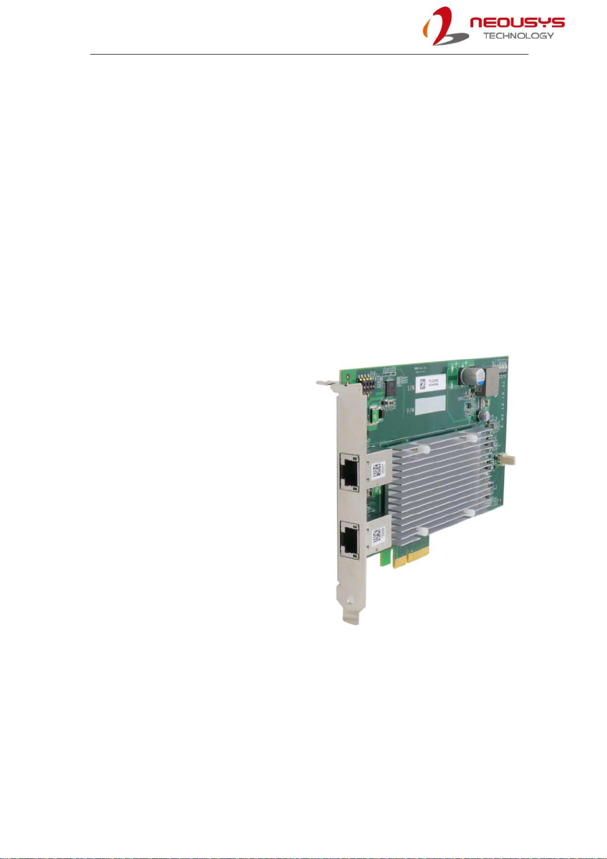
1.1 PCIe-PoE550X Overview
PCIe-PoE550X features 10GbE NIC incorporating Power over Ethernet (PoE+)
capability. It features Neousys’ proven 802.3at PoE+ technology and refined power
design to ensure optimal signal integrity over 10G PHY and maximal bandwidth. The
combination of 10GbE and PoE
opens the door to new applications
such as high-performance WiFi
access points and high-speed/
high-definition industrial cameras
over single Ethernet cable.
10GBAST-T leverages twisted-pair
copper cable and RJ-45 connector
that dramatically reduces the
deployment cost of 10G network.
PCIe-PoE550X provides 10Gbit/s
connections over a distance of up to
100 meters with CAT 6a cable or 55
meters with CAT 6 cable. It also
supports upcoming NBASE-T
standard as well as backward
compatibility with existing
1000BASE-T GbE network so you can easily implement it into your current network
infrastructure.

PCIe-PoE550X
10
1.2 PCIe-PoE550X Specifications
Bus Interface Gen3 PCI Express x4
# of 10 GbE Port 2x 10 GbE ports by Intel® X550-AT2 controller,
supporting 15.5 KB jumbo frame, teaming and IEEE 1588
Network Protocol
Support
IEEE 802.3 Ethernet interface for 10GBASE-T (IEEE 802.3an),
NBASE-T (IEEE 802.3bz) and 1000BASE-T (IEEE 802.3ab)
PoE Capability Compliant with IEEE 802.3at-2009 (PoE+), each port delivers up
to 25.5 W of power
Cable Requirement For 10GBASE-T: CAT 6a (100 meters) or CAT 6 (55 meters)
For 5Gbps NBASE-T: CAT 6 (100 meters)
For 2.5Gbps NBAST-T: CAT 5e (100 meters)
Power Requirement Maximum 11.5W for 2x 10 GbE operation
Maximum 51W for powering PoE+ devices
EMC CE Class A, according to EN 55024/55032
FCC ClassA, according to FCC Part 15, Subpart B
EMS IEC 61000-4-x Class/ Level 3
Operating Temperature 0℃~ 60℃with air flow
Dimension 167.7 mm (W) x 111.2 mm (H)
1.3 PCIe-10G550X Specifications
Bus Interface Gen3 PCI Express x4
# of 10 GbE Port 2x 10 GbE ports by Intel® X550-AT2 controller,
supporting 15.5 KB jumbo frame, teaming and IEEE 1588
Network Protocol
Support
IEEE 802.3 Ethernet interface for 10GBASE-T (IEEE 802.3an),
NBASE-T (IEEE 802.3bz) and 1000BASE-T (IEEE 802.3ab)
Cable Requirement For 10GBASE-T: CAT 6a (100 meters) or CAT 6 (55 meters)
For 5Gbps NBASE-T: CAT 6 (100 meters)
For 2.5Gbps NBAST-T: CAT 5e (100 meters)
Power Requirement Maximum 11.5W for 2x 10 GbE operation
EMC CE Class A, according to EN 55024/55032
FCC ClassA, according to FCC Part 15, Subpart B
EMS IEC 61000-4-x Class/ Level 3
Operating Temperature 0℃~ 60℃with air flow
Dimension 167.7 mm (W) x 111.2 mm (H)

PCIe-PoE550X
11
1.4 Dimension
NOTE
All measurements are in millimeters (mm).
PCIe-PoE550X
12
2 System Overview
Upon receiving and unpacking your system, please check immediately if the package
contains all the items listed in the following table. If any item(s) are missing or damaged,
please contact your local dealer or Neousys Technology.
2.1 PCIe-PoE550X Packing List
System
Pack PCIe-PoE550X Qty
1 PCIe-PoE550X 1
2 Neousys Drivers & Utilities DVD 1
2.2 PCIe-PoE550X

PCIe-PoE550X
13
2.3 PCIe-PoE550X Status LEDs
Item Description
10Gbit PoE+
Ethernet port
The two 10Gbit Ethernet ports are implemented via Intel®
X550-AT2 controller that supports 15.5K jumbo frame,
teaming and IEEE 1588
Active/Link LED (1)
LED Color
Status
Description
Green
Off
Ethernet port is disconnected
On
Ethernet port is connected and no data transmission
Flashing
Ethernet port is connected and data is transmitting/receiving
Speed LED (2)
LED Color
Status
Description
Green or
Orange
Off
100 Mbps
Orange
1000 Mbps
Green
10 Gbps
PCIe-PoE550X
14
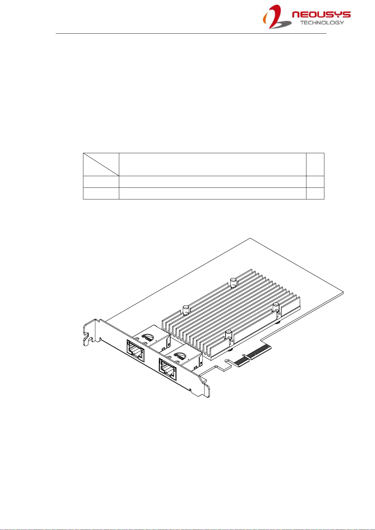
2.4 DIP Switches
PCIe-PoE550X features individual
per-port power on/off control via
Neousys’API so you may manually
cut off or resume the power delivery
to the connected PoE device. This
feature is designed for failure
recovery in the field to reset
connected devices. In case you have
installed multiple cards, there is a set
of DIP switches (shown below) for
users to configure board ID. The
board ID can be used as a parameter
in API to specify the card.
2.4.1 Switching Between PoE (af) and PoE+ (at) Mode
The PCIe-PoE550X offers two modes, users can choose between af mode (IEEE
802.3af) or high at mode (IEEE 802.3at) by configuring DIP switch 4.
Mode DIP Switch 4 Position Power Supplied
IEEE
802.3af
15.4W
Up to 350mA per port
IEEE
802.3at
25.5W
Up to 720mA per port

PCIe-PoE550X
15
2.4.2 Board ID Settings
The following illustrations describe DIP switch board ID settings. When installing
multiple cards, please remember to set a different ID for each card.
Board ID DIP Switch Position (P1 ~ P3)
0
1
2
3
4
5
6
7

PCIe-PoE550X
16
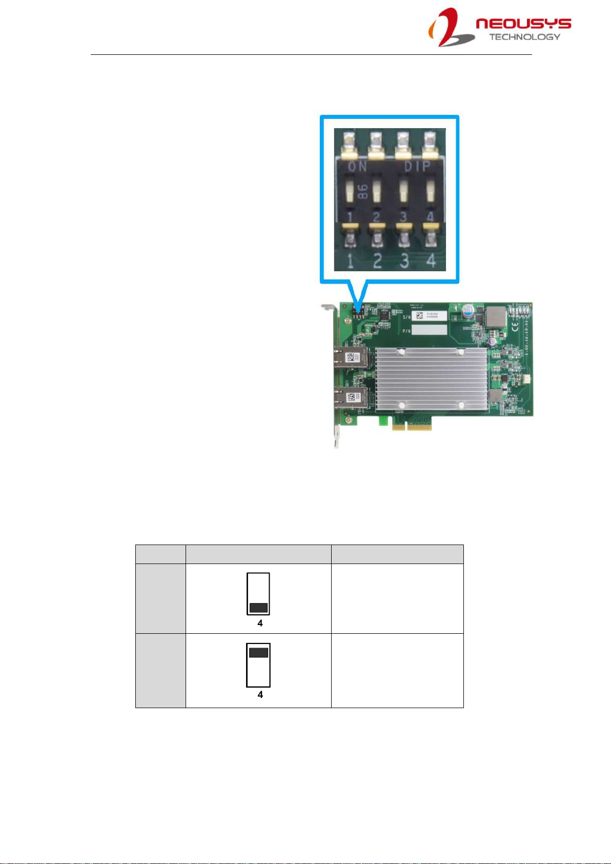
3 PCIe-PoE550X Card Installation
Before disassembling the system enclosure and installing the PCIe-PoE550X card,
please read the following instructions:
DO NOT remove the card out of the anti-static until you are ready to install it into
the system.
It is recommended that only qualified service personnel should install and service
this product to avoid injury or damage to the system.
Please observe all ESD procedures at all times to avoid damaging the equipment.
Before disassembling your system, please make sure the system has powered off,
all cables and antennae (power, video, data, etc.) are disconnected.
Place the system on a flat and sturdy surface (remove from mounts or out of
server cabinets) before proceeding with the installation/ replacement procedure.
PCIe-PoE550X
17
3.1 PCIe-PoE550X Installation
WARNING
DO NOT remove PCIe-PoE550X out of the anti-static bag until you are ready to install it
into the system.
1. Save and close all work in progress.
2. Power off and unplug the power cable from the system you wish to install to.
3. Open the chassis (side panel) of the computer you wish to install the
PCIe-PoE550X into.
4. Locate the x4 PCIe slot or a spare and compatible x8/ x16 PCIe slot.
5. Align and insert PCIe-PoE550X’s gold finger into PCIe slot while making sure the
panel is inserted into the hinge.
PCIe-PoE550X
18
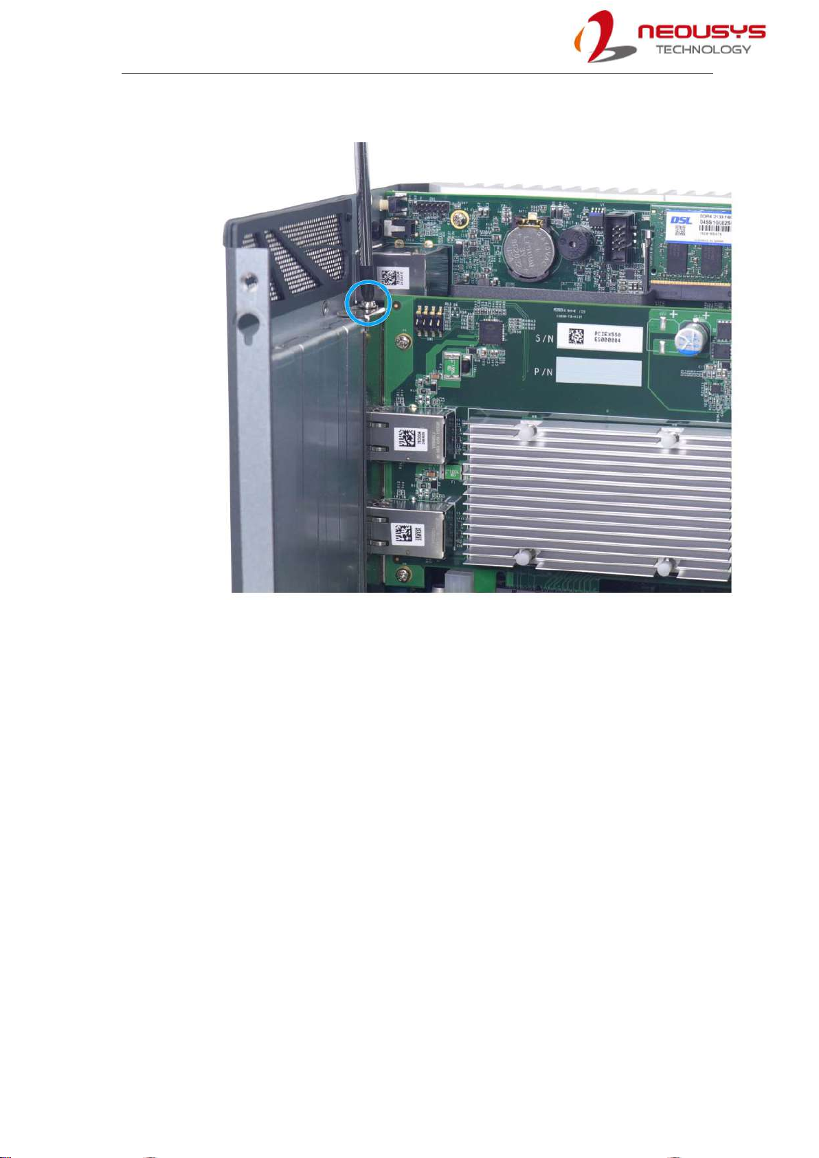
6. Secure PCIe-PoE550X to the chassis with a screw.
7. Reinstall the system’s chassis (panel) to complete the hardware installation
process.

PCIe-PoE550X
19
3.2 Software Installation
Some operating systems may have built-in drivers included and automatically complete
the installation upon entering the system. However, it is still recommended to run and
install drivers provided by Neousys to take advantage of all the functions offered. To
install the software component, please refer to the following procedure.
3.2.1 Installing Drivers Using Automatic Driver Installation
1. Plug in the power cable and power up the system.
2. Once you are in the system, insert the Neousys driver DVD included in the
package into the DVD-ROM.
3. A setup utility launches and the following dialog appears, Click on the “Automatic
Driver Installation”. The setup utility will automatically detect your operating system
and install corresponding driver for PCIe-PoE550X. The installation process takes
about 2 ~ 3 minutes and once all drivers have been installed, the setup utility will
automatically reboot your Windows to complete the installation process.
3.2.2 Installing Drivers Manually
You may also manually install the driver for PCIe-PoE550X. Please refer to the
following information about installing the driver for different operating system.
Windows 10 64-bit
x:\Driver_Pool\GbE_I210_I350\Win_10_64_CFL\APPS\PROSETDX\Winx64\DxSetu
p.exe

PCIe-PoE550X
20
4 Driver and Network Settings
PCIe-PoE550X offers 10-Gigabit Ethernet connectivity via Intel® X550-AT2 controller.
When connecting to a high-speed PoE device, such as a GigE camera, you can
configure driver settings for optimum transmission throughput and connection stability.
4.1 Jumbo Frame
Jumbo frames are Ethernet frames with more than 1500 bytes of payload. By
increasing the payload size, large data packets can be transferred with less interruption,
which reduces CPU utilization and increases overall data throughput. Intel® X550-AT2
10GbE controller supports jumbo frame size of up to 15.5 Kbytes. Once the Intel®
X550-AT2 controller driver is installed, you may configure jumbo frame settings by
executing the following steps:
1. On your keyboard, press Windows key + E, right click on Network and select
Properties.
Table of contents


