Neptune Technology TRICON SmartTrol Product manual
TRICON®SmartTrol™
TRICON SMARTTROL INSTALLATION AND MAINTENANCE GUIDE
INSTALLATION AND MAINTENANCE
GUIDE

TRICON®SMARTTROL™INSTALLATION AND MAINTENANCE GUIDE 2
This manual is an unpublished work and contains the trade secrets and confidential information of
Neptune Technology Group Inc., which are not to be divulged to third parties and may not be reproduced
or transmitted in whole or part, in any form or by any means, electronic or mechanical, for any purpose,
without the express written permission of Neptune Technology Group Inc. All rights to designs or
inventions disclosed herein, including the right to manufacture, are reserved to Neptune Technology
Group Inc.
Neptune engages in ongoing research and development to improve and enhance its products. Therefore,
Neptune reserves the right to change product or system specifications without notice.
Trademarks Used in this Manual
Neptune, TRICON, and SmartTrol are registered trademarks of Neptune Technology Group Inc.
Other brands or product names are the trademarks or registered trademarks of their respective holders.
neptunetg.com
Neptune Technology Group
1600 Alabama Highway 229
Tallassee, AL 36078
800-633-8754 f334-283-7293
© 2019 Neptune Technology Group Inc. All Rights Reserved. The trademarks, logos and service marks displayed in this
document herein are the property of Neptune Technology Group Inc., its affiliates or other third parties. Availability and
technical specifications are subject to change without notice.

TRICON®SMARTTROL™INSTALLATION AND MAINTENANCE GUIDE 3
INTRODUCTION ............................................................................................... 4
TYPICAL APPLICATION .................................................................................... 5
OPERATING THE SMARTTROL........................................................................... 6
GENERAL DESCRIPTION AND PRINCIPLES OF OPERATION................................. 7
SPECIFICATIONS ............................................................................................. 9
MOUNTING AND INSTALLATION...................................................................... 10
CONNECTIONS TO THE SMARTTROL ................................................................ 11
PROGRAMMING WORKSHEET.......................................................................... 18
USING THE WORKSHEET ................................................................................. 19
SETTING UP THE SMARTTROL......................................................................... 25
RS-232C SERIAL COMMUNICATION OPERATIONS............................................. 29
WARRANTY .................................................................................................... 32
APPENDIX A: TRICON/E SPECIFICATIONS........................................................ 33
APPENDIX B: TRICON/S PERFORMANCE DATA ................................................. 37
APPENDIX C: REGISTER TRACKING ................................................................. 38
1
2
3
4
5
6
7
8
9
10
11
12
CONTENTS

TRICON®SMARTTROL™INSTALLATION AND MAINTENANCE GUIDE 4
CHAPTER 1INTRODUCTION
CHAPTER 1INTRODUCTION
The Neptune SmartTrol™is a versatile microprocessor-based controller for use with TRICON/E®
electronic registers. The main function of the unit is to display rate and totalization values and
control relays for batching or alarming. TheSmartTrol allows two meter flows to be measured,
separately scaled for both rate and total, then combined into one overall rate and one total. This
dual input capability permits the SmartTrol to be used with TRU/FLO®and PROTECTUS®meters
having two separate measuring elements to monitor flow.

TRICON®SMARTTROL™INSTALLATION AND MAINTENANCE GUIDE 5
CHAPTER 2TYPICAL APPLICATION
CHAPTER 2TYPICAL APPLICATION
In the illustration below, the SmartTrol is used to power a single TRICON/E transmitter which, in
turn, provides digital pulses to the SmartTrol. TheSmartTrol scales the pulse input to determine rate
of flow and total quantity through the meter. The SmartTrol then uses the rate of flow or total values
to operate two relays which may be used for single or two-stage batching, or under/over alarming.
The SmartTrol may be ordered with optional RS-232C serial communications, or 4-20 mA analog
output, or both.
TRICONE/E
XMTR
COMPUTER
CHART
RECORDER
BATCHING
or
ALARMS
+12VDC
RS-232C
COMM*
4-20 mA
OUTPUT*
*OPTIONAL FEATURES
PULSE
OUTPUT
RELAY A
RELAY B
SmartTrol
TRICON®SMARTTROL™INSTALLATION AND MAINTENANCE GUIDE 6
CHAPTER 3OPERATING THE SMARTTROL
When power is initially applied, the SmartTrol is in the normal operating mode in which Total, Grand Total,
and Rate are available for view.
To view Total, Grand Total, or Rate, apply power.
Press Display
VER # . # (Displayed 1 second)
######## (Current value of Total)
When power is applied to the SmartTrol, the current value of Total is displayed as indicated. Total remains
on the display until another variable is selected. Total represents the volume of liquid through the meter
since Total was last reset. The value of Total is preserved when power is removed from the SmartTrol and is
restored when power is reapplied. Total is updated only while power is applied.
To display Grand Total,
Press Display
ENT GR TOTAL (Display 1 second)
######## (Current value of Grand Total blinks)
Grand Total also represents the volume of liquid through the meter since Grand Total was last reset. Like the
value of Total, Grand Total is preserved when power is removed form the SmartTrol, and is restored when
power is reapplied. Grand Total is updated only while power is applied.
To return the display to Total,
Press Display
ENT ######## (Current value of Total)
To display Rate,
Press Display
C (Rate Total) R ###### (Current value of Rate)
Notice when Rate is displayed, the first character position on the display is “R”. Rate represents the volume
of liquid passing through the meter in some unit of time such as gallons per minute.
To return the display to Total,
Press Display
C (Rate/Total) ######## (Current value of Total)
Before using the SmartTrol you must program several setup values from the Setup Menu. Fill out the
Worksheet (Page 18) using the instructions beginning on Page 19. Instructions for setting up the SmartTrol
begin on Page 25. To enter the Menu from the normal operating mode, press the “D” (MENU) key.
CHAPTER 3OPERATING THE SMARTTROL

TRICON®SMARTTROL™INSTALLATION AND MAINTENANCE GUIDE 7
CHAPTER 4GENERAL DESCRIPTION AND PRINCIPLES OF OPERATION
4.1 DISPLAY
The SmartTrol shows one of three different variables on its 8-digit, alphanumeric displays: Total, Grand Total,
or Rate. Total is typically the volume through the meter in units such as gallons, cubic feet, or cubic meters.
Grand Total is similar to Total but continues to count when Total is reset (very useful for many batching
operations). Rate is the volume flowing through the meter per unit of time. Since Rate and Total values are
scaled independently, different units may be used for each, e.g., Rate displayed in gallons/minute and Total in
cubic feet.
4.2 RESETS
Resets return the value of Total or Grand Total to a predetermined point to begin counting up to or counting
down from. Resets may be manually entered through the keypad by pressing the “CLR” key, remotely
entered by applying 3 to 30 VDC pulse for a minimum of 5 seconds to Pin 5, or by a host computer via
RS-232C communications. The SmartTrol may also be programmed to reset automatically when the
endpoint is reached.
4.3 PRESETS
Presets are the values of Total or Grand Total the totalizer must reach, or the Rate of flow the ratemeter must
register, to trigger relay operation. Total may be configured to count up from zero after a reset, or to count
down from the preset value to zero after reset. Grand Total will only count up from zero to the preset value
after a reset.
4.4 RELAYS
The SmartTrol may be used for monitoring or for control purposes, such as batching. There are two control
relays in the SmartTrol whose operations are based on preset values of Rate, Total, or Grand Total. Each relay
may be programmed to its own preset value. The presets can be programmed to allow two-stage stepping of
a process providing precise control of a dispensing or blending application. For batching applications, an Auto
Reset mode can be selected for continuous blending processes. When Total or Grand Total values are used,
relay duration may be set from 1 to 99 seconds or minutes. NOTE: RELAY OPERATION IS DISABLED WHEN
THE MENU FUNCTION IS ENTERED.
4.5 K FACTOR
The K Factor is divided into the input pulse to convert them into convenient units of measurement. Separate
K Factors are entered into the rate and counter sections of the SmartTrol for each input, and K Factors may be
mixed. Thus, you may batch (totalize) in gallons and display Rate in cubic feet per hour.
CHAPTER 4GENERAL DESCRIPTION AND PRINCIPLES OF OPERATION

TRICON®SMARTTROL™INSTALLATION AND MAINTENANCE GUIDE 8
4.6 RATEMETER
The ratemeter selection of the SmartTrol calculates Rate based on time between pulses from
a maximum of two inputs. The resulting value of input pulses per second is then divided by the
K Factor to display the Rate in units of volume per time.
4.7 COUNTER
The counter section of the SmartTrol divides pulses from a maximum of two inputs by the Count
K Factors to determine Total and Grand Total volumes through the meter in convenient units
of volume.
4.8 LOCKOUT
Once the SmartTrol is configured and operating, unauthorized changes can be prevented by use of
a lock-out code that must be entered to allow modification of the configuration. The code may be
modified periodically to maintain secure operations.
4.9 RS-232C COMMUNICATIONS
The SmartTrol may be ordered with RS-232C computer communications. This option allows the
SmartTrol to communicate with virtually any computer that has an RS-232C serial communications
port. The data in the SmartTrol may be read or modified by computer to allow customization of the
process. In addition, up to 15 SmartTrols may be tied to the same RS-232C port providing a path for
future expansion.
4.10 4-20 mA OUTPUT
The 4-20 mA option produces an analog output that is scaled based on Rate as calculated by the
SmartTrol. You may select the upper and lower limits of Rate corresponding to the 4-20 mA range
appropriate for the application.
4.11 ENTERING DECIMAL POINTS
To include a decimal point as part of the number entered through the keypad, press the “D” button
after the digit that you would like to place the decimal point. The decimal point will appear to the
right of that digit.
CHAPTER 4GENERAL DESCRIPTION AND PRINCIPLES OF OPERATION

TRICON®SMARTTROL™INSTALLATION AND MAINTENANCE GUIDE 9
CHAPTER 5SPECIFICATIONS
CHAPTER 5SPECIFICATIONS
n HOUSING: High-impact plastic case with NEMA 4X front panel.
n DIMENSIONS: Reference 6.2, Page 12.
nDISPLAY: 8-character, 0.55” high, 15 segment, red-orange LED.
nINPUT POWER: 110 VAC +/- 15% or 12 to 27 VDC.
nCURRENT: 5.3 VA at rated AC voltage or maximum 280 mA DC.
nOUTPUT POWER: (On AC power units only) +12 VDC at 100 mA
Separate isolated 12 VDC at 100 mA to allow +/- 12
VDC or +24 VDC, regulated +/- 5% worst case.
nTEMPERATURE: Operating: +32° F (0° C) to +130° F (+54° C).
Storage: -40° F (-40° C) to +200° F (+93° C).
nMEMORY: EEPROM stores all programming, display mode, and count data for a
minimum of 10 years if power is lost.
nRESET: Front panel push button – “CLR” resets displayed number and control output.
Remote input (Terminal 5) – Open or 0 to 1 VDC (low), 3 to 30 VDC (high),
10K ohm input impedance to ground. Minimum pulse on/off time 5 msec.
nPULSE INPUT: High impedance pulse input. Open or 0 to 1 VDC (low), 3 to 30 VDC (high),
10K ohm input impedance.
1KHz maximum speed (minimum on/off 25 usec).
nANALOG OUTPUT: 4-20 mA sinking output, 3-24 VDC +/- 100 uA worst case.
nRELAY CONTACTS: 10 amp, 120/240 VAC or 28 VDC.

TRICON®SMARTTROL™INSTALLATION AND MAINTENANCE GUIDE 10
CHAPTER 6MOUNTING AND INSTALLATION
6.1 PANEL MOUNTING
The SmartTrol can be mounted in any panel with a thickness between .047” (1.2 mm) and .187” (4.7mm). It is
shipped with two side mounting brackets and screws as well as a panel gasket. The gasket fits between the
SmartTrol bezel and the front panel to form a NEMA 4 splash-proof assembly when properly panel-mounted.
To install the SmartTrol into a panel, slip the gasket over the case of the SmartTrol and set the gasket against the
SmartTrol bezel. Insert the unit through the front of the panel until it engages the panel. Install the self-tapping
screws provided in the mounting brackets and insert the brackets into the side slots of the unit. Tighten the
screws firmly to attach the SmartTrol bezel to the panel.
6.2 DIMENSIONS
CHAPTER 6MOUNTING AND INSTALLATION

TRICON®SMARTTROL™INSTALLATION AND MAINTENANCE GUIDE 11
CHAPTER 7CONNECTIONS TO THE SMARTTROL
7.1 POWER CONNECTION FOR ALTERNATING CURRENT (AC)
(Refer to 7.5.1, Page 12)
Be certain all power is removed from the wire before connecting the power wiring to the SmartTrol. Also be
sure that the power is 120 VAC to prevent damage due to application of incorrect voltage. Connect the AC
power across terminals 17 and 18 on the large terminal block. Double-check all wiring before applying power to
the SmartTrol.
7.2 POWER CONNECTION FOR DIRECT CURRENT (DC)
(Refer to 7.5.5, Page 15)
You may choose to power the SmartTrol with DC. Be certain that all power is removed from the wire before
connecting the power wiring to the SmartTrol. Also be sure that the power is 12 to 27 VDC at .5 amp. Connect
+DC to terminal 14 and ground to terminal 12 on the large terminal block. Double-check all wiring before applying
power to the SmartTrol. If the SmartTrol is powered by DC, it cannot be used to provide DC power for TRICON/E
operation. Use the same DC source to power both the SmartTrol and associated TRICON/E transmitters.
7.3 RELAY OUTPUT CONNECTION
(Refer to 7.5.1, Page 12 and 7.5.5, Page 15)
Be certain that all power wiring is de-energized before connecting relay outputs to controlled devices. The relay
contacts are located on the six-pin terminal block. The relay associated with Preset A uses terminasl 1 (normally
open contact), 2 (normally closed contact), and 3 (common contact). The relay associated with Preset B uses
terminals 4 (normally open contact), 5 (normally closed contact), and 6 (common contact).
7.4 4-20 mA OPTION
(Refer to 7.5.4, Page 14)
The 4-20 mA output option is connected to terminal 10 of the large terminal block. The output sinks current from
a voltage source. The receiving instrument (Ammeter) must NOT be ground-referenced in order to be compatible
with this output.
7.5 SCHEMATICS
The following pages illustrate the SmartTrol in various configurations and wiring for each. Your specific application
may not be represented, but it may be a composite of several of the illustrations provided.
CHAPTER 7CONNECTIONS TO THE SMARTTROL

TRICON®SMARTTROL™INSTALLATION AND MAINTENANCE GUIDE 12
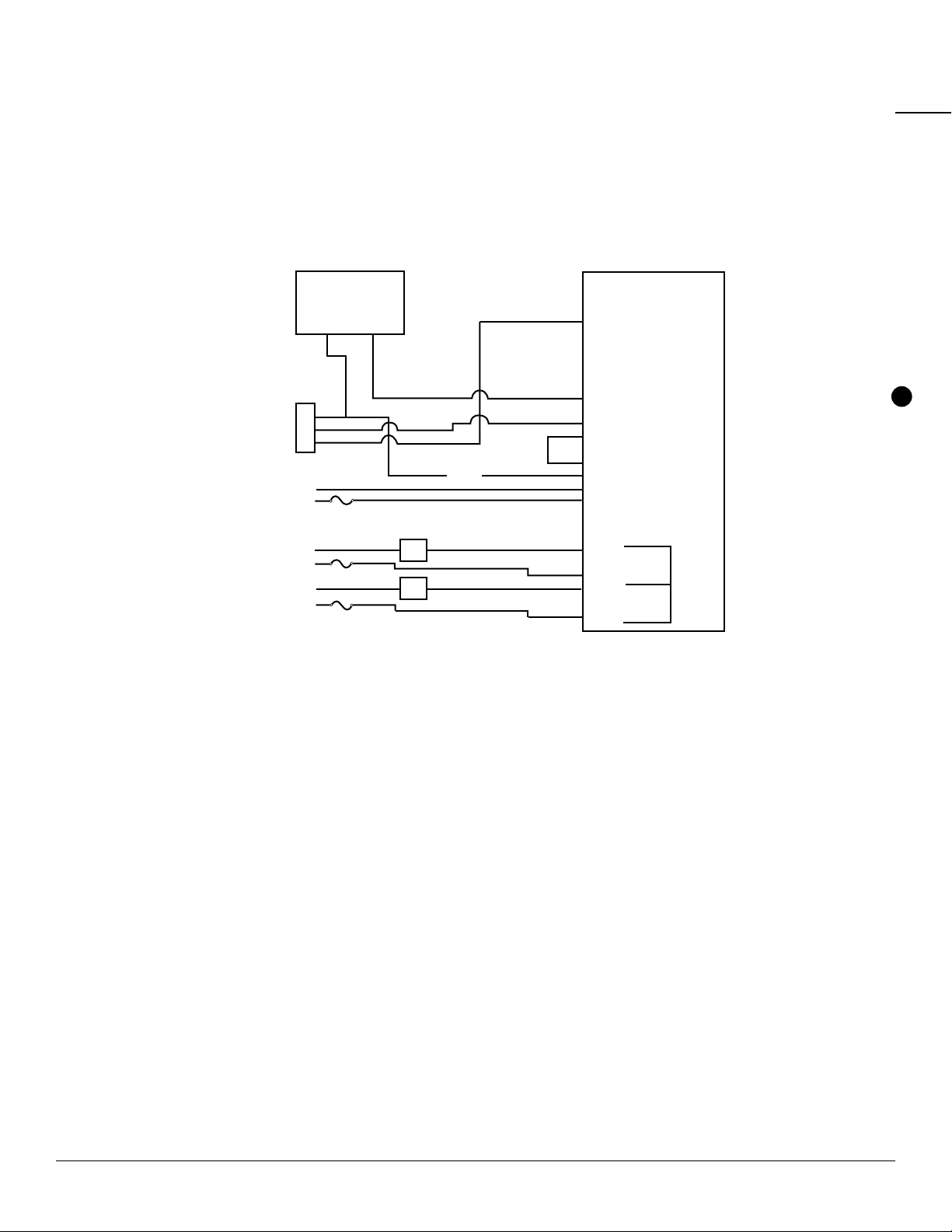
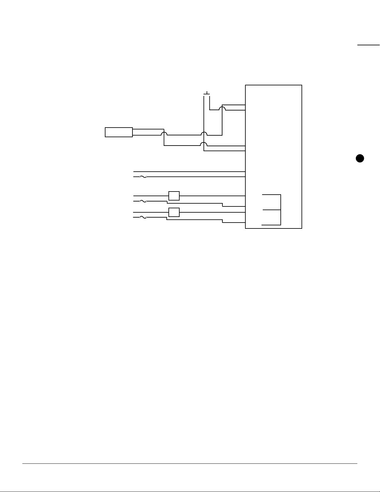
7.5.1 SmartTrol and Single TRICON/E Transmitter with Pulse Output and Remote Reset
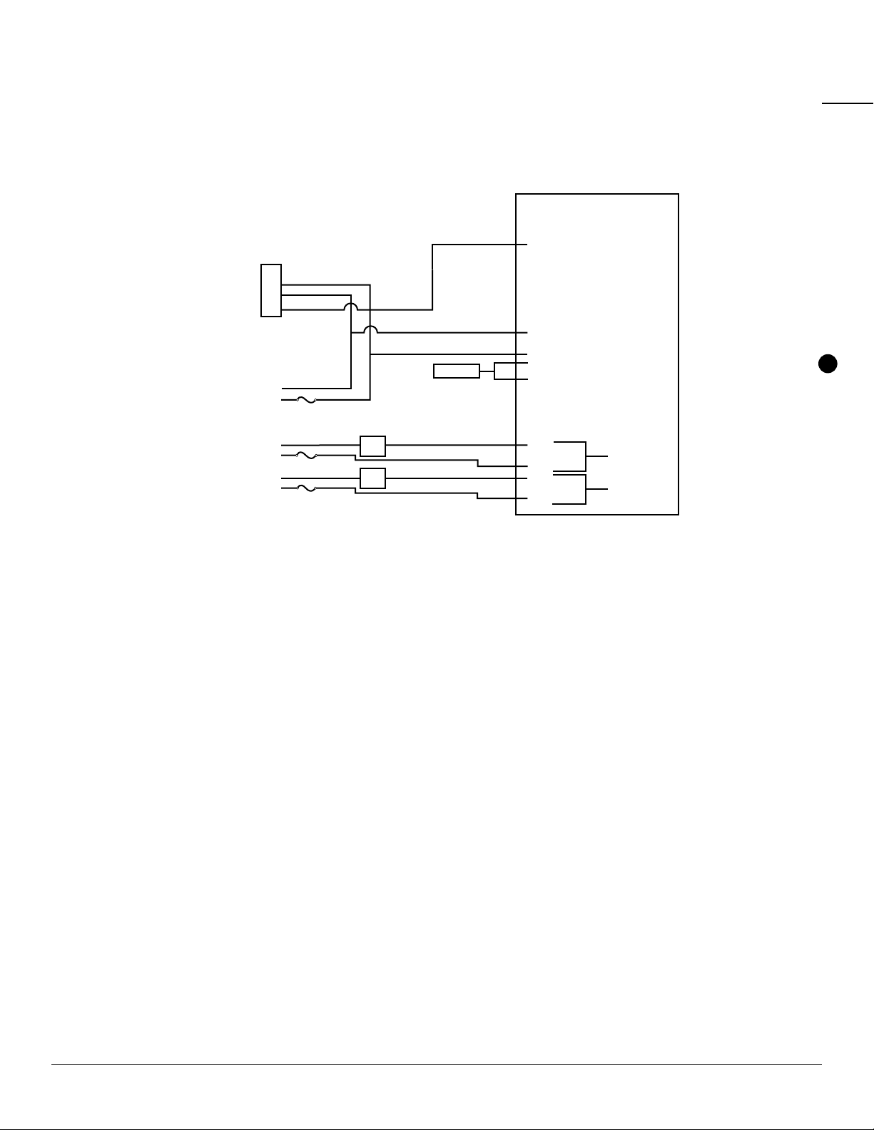
7.5.2 SmartTrol and Two TRICON/E Transmitters with Pulse Output and Remote Reset
7.5.1
SmartTrol
1 no
2 nc
3 common
4 no
5 nc
6 common
Relay A
Relay B
3
4
5
TRICON/E
+12V
GND
PULSE OUTPUT
USER
LOAD
USER
LOAD
AC-1
120 VAC
Neutral
Line
AC-2
Neutral
Line
AC-3
Neutral
Line
Fuse
Fuse
Fuse
REMOTE
RESET 1 Not Used
2 Scaled Output
3 Input B
4 Input A
5 Reset Input
6 Not Used
7 Not Used
8 Not Used
9 Not Used
10 No Connection (4-20 mA Output)
11 No Connection
12 Ground
13 +12 VDC Out
14 DC Power In
15 Isolated -12 VDC
16 Isolated +12 VDC
17 AC In
18 AC In
19 Preset B Transistor
20 Preset A Transistor
SmartTrol
1 Not Used
2 Scaled Output
3 Input B
4 Input A
5 Reset Input
6 Not Used
7 Not Used
8 Not Used
9 Not Used
10 No Connection
11 No Connection
12 Ground
13 +12 VDC Out
14 DC Power In
15 Isolated -12 VDC
16 Isolated +12 VDC
17 AC In
18 AC In
19 Preset B Transistor
20 Preset A Transistor
1 no
2 nc
3 common
4 no
5 nc
6 common
Relay A
Relay B
3
4
5
3
4
5
TRICON/E
TRICON/E
+12V
GND
PULSE OUTPUT
+12V
GND
PULSE OUTPUT
USER
LOAD
USER
LOAD
AC-1
120 VAC
Neutral
Line
AC-2
Neutral
Line
AC-3
Neutral
Line
Fuse
Fuse
Fuse
7.5.2
CHAPTER 7CONNECTIONS TO THE SMARTTROL

TRICON®SMARTTROL™INSTALLATION AND MAINTENANCE GUIDE 13
7.5.3 SmartTrol and 4-20 mA TRICON/E and SmartChart
4-20 mA TRICON/E must be powered by 24 VDC. The SmartTrol is able to produce 24 VDC by “stacking”
two independent 12 VDC power supplies. Configure the SmartTrol to provide +24 VDC by tying the
+12 VDC (PIN 15). This jumper causes +24 VDC to appear across PIN 16 referenced to ground (PIN 12).
1 Not Used
2 Scaled Output
3 Input B
4 Input A
5 Reset Input
6 Not Used
7 Not Used
8 Not Used
9 Not Used
10 No Connection (4-20 mA Output)
11 No Connection
12 Ground
13 +12 VDC Out
14 DC Power In
15 Isolated -12 VDC
16 Isolated +12 VDC
17 AC In
18 AC In
19 Preset B Transistor
20 Preset A Transistor
SmartTrol
1 no
2 nc
3 common
4 no
5 nc
6 common
Relay A
Relay B
1
2
3
4
5
TRICON/E
GND
PULSE OUTPUT
+24 VDC
AC-1
120 VAC
Neutral
Line
AC-2
Neutral
Line
AC-3
Neutral
Line
Fuse
Fuse
Fuse
USER
LOAD
USER
LOAD
CL+
CL-
Smart Chart
4-20mA
Source Return
+ -
7.5.3
+24V
CHAPTER 7CONNECTIONS TO THE SMARTTROL
TRICON®SMARTTROL™INSTALLATION AND MAINTENANCE GUIDE 14
7.5.4 SmartTrol with 4-20 mA Output Option and SmartChart and
Single TRICON/E Transmitter with Pulse Output
SmartTrol
1 Not Used
2 Scaled Output
3 Input B
4 Input A
5 Reset Input
6 Not Used
7 Not Used
8 Not Used
9 Not Used
10 No Connection (4-20 mA Output)
11 No Connection
12 Ground
13 +12 VDC Out
14 DC Power In
15 Isolated -12 VDC
16 Isolated +12 VDC
17 AC In
18 AC In
19 Preset B Transistor
20 Preset A Transistor
1 no
2 nc
3 common
4 no
5 nc
6 common
Relay A
Relay B
3
4
5
TRICON/E
+24V
GND
PULSE OUTPUT
+24 VDC
AC-1
120 VAC
Neutral
Line
AC-2
Neutral
Line
AC-3
Neutral
Line
Fuse
Fuse
Fuse
USER
LOAD
USER
LOAD
CL+
CL-
Smart Chart
4-20mA
Source Return
+ -
7.5.4
CHAPTER 7CONNECTIONS TO THE SMARTTROL
TRICON®SMARTTROL™INSTALLATION AND MAINTENANCE GUIDE 15
7.5.5 SmartTrol Powered by +24 VDC, Relays Controlling +24 VDC, and
Single TRICON/E Transmitter with Pulse Output
The SmartTrol may be powered by an external DC power supply. The supply must provide 12-27 VDC and
at least 250 mA of current. The positive side (+DC) of the supply should be connected to terminal 14 and
the negative (or ground) side to terminal 12. Units Powered by DC voltage do not have an isolated voltage
on terminals 15 and 16.
SmartTrol
1 Not Used
2 Scaled Output
3 Input B
4 Input A
5 Reset Input
6 Not Used
7 Not Used
8 Not Used
9 Not Used
10 No Connection (4-20 mA Output)
11 No Connection
12 Ground
13 +12 VDC Out
14 DC Power In
15 Isolated -12 VDC
16 Isolated +12 VDC
17 AC In
18 AC In
19 Preset B Transistor
20 Preset A Transistor
1 no
2 nc
3 common
4 no
5 nc
6 common
Relay A
Relay B
3
4
5
TRICON/E
GND
PULSE OUTPUT
DC-1
Ground
+24V
DC-2
Ground
+24V
DC-3
Ground
+24V
Fuse
DO NOT USE
Fuse
Fuse
USER
LOAD
USER
LOAD
7.5.5
+24V
CHAPTER 7CONNECTIONS TO THE SMARTTROL
TRICON®SMARTTROL™INSTALLATION AND MAINTENANCE GUIDE 16
7.5.6 SmartTrol and Single TRICON/S Transmitter with Pulse Output and Remote Reset
NOTE: The SmartTrol must be ordered from the factory configured for use with the TRICON/S.
1 Not Used
2 Scaled Output
3 Input B
4 Input A
5 Reset Input
6 Not Used
7 Not Used
8 Not Used
9 Not Used
10 No Connection
11 No Connection
12 Ground
13 +12 VDC Out
14 DC Power In
15 Isolated -12 VDC
16 Isolated +12 VDC
17 AC In
18 AC In
19 Preset B Transistor
20 Preset A Transistor
7.5.6
Smart Trol
1 no
2 nc
3 common
4 no
5 nc
6 common
Relay A
Relay B
USER
LOAD
USER
LOAD
CONTACTS
TRICON/S GND
PULSE OUTPUT
AC-1
120 VAC
Neutral
Line
AC-2
Neutral
Line
AC-3
Neutral
Line
Fuse
Fuse
Fuse
Remote
Reset
CHAPTER 7CONNECTIONS TO THE SMARTTROL

TRICON®SMARTTROL™INSTALLATION AND MAINTENANCE GUIDE 17
1 Not Used
2 Scaled Output
3 Input B
4 Input A
5 Reset Input
6 Not Used
7 Not Used
8 Not Used
9 Not Used
10 No Connection (4-20 mA Output)
11 No Connection
12 Ground
13 +12 VDC Out
14 DC Power In
15 Isolated -12 VDC
16 Isolated +12 VDC
17 AC In
18 AC In
19 Preset B Transistor
20 Preset A Transistor
SmartTrol
Smart Trol W/4-20mA Output Option and Remote Device and Battery Powered TRU/MAG
1 no
2 nc
3 common
4 no
5 nc
6 common
Relay A
Relay B
SmartTrol DIP Switch Settings for TRU/MAG
4.7KΩPull Up Resistors to +5 VDC on input for NPN open
collector transistors
ON ON ON
S1 S2 S3 S4
Fuse
AC - 1
120 VAC
Neutral Line
White ( - )
Green (+)
TRU/MAG
CABLE
Remote Device
4-20 mA
Source Return
+ -
7.5.7
7.5.7 SmartTrol with 4-20 mA Output Option and Remote Device and Battery-Powered TRU/MAG™
7.5.8 SmartTrol with 4-20 mA Output Option and Remote Device and DC-Powered TRU/MAG
CHAPTER 7CONNECTIONS TO THE SMARTTROL
1 Not Used
2 Scaled Output
3 Input B
4 Input A
5 Reset Input
6 Not Used
7 Not Used
8 Not Used
9 Not Used
10 No Connection (4-20 mA Output)
11 No Connection
12 Ground
13 +12 VDC Out
14 DC Power In
15 Isolated -12 VDC
16 Isolated +12 VDC
17 AC In
18 AC In
19 Preset B Transistor
20 Preset A Transistor
Smart Trol W/4-20mA Output Option and Remote Device and DC Powered TRU/MAG
SmartTrol
1 no
2 nc
3 common
4 no
5 nc
6 common
Relay A
Relay B
SmartTrol DIP Switch Settings for TRU/MAG
4.7KΩPull Up Resistors to +5 VDC on input for NPN open
collector transistors
ON ON ON
S1 S2 S3 S4
Fuse
AC - 1
120 VAC
Neutral Line
White ( - )
Green (+)
Black ( - )
Red (+)
TRU/MAG
CABLE
Remote Device
4-20 mA
Source Return
+ -
24 VDC/2 AMPS
Power Supply
24 VDC
+ -
7.5.8

TRICON®SMARTTROL™INSTALLATION AND MAINTENANCE GUIDE 18
CHAPTER 8PROGRAMMING WORKSHEET
CONFIGURED BY: ___________________ DATE: _____/ ______/ ______
MODEL NUMBER:___________________ APPLICATION: ____________
CALCULATION AREA________________
COUNTER
K FACTOR A ________________________
K FACTOR B ________________________
RESET TO 0 _____________RESET TO PRESET_______
AUTOMATIC RESET_________MANUAL RESET_______
DECIMAL LOCATION ___# ___# ___# ___# ___# ___# ___# ___#
8 7 6 5 4 3 2 1
RATEMETER
K FACTOR A ______________________
K FACTOR B_______________________
WEIGHT _________________________
WINDOW ________________________
SIG. FIG. _________________________
LOCK OUT CODE ____________________
RS-232C COMMUNICATIONS (SKIP IF UNIT DOES NOT HAVE OPTION)
UNIT NUMBER ______________________
BAUDRATE
300 ____ 600 _____ 1200 ____ 2400 ____ 4800 ____ 9600 ____
PARITY BIT
EVEN ___ ODD ____ SPACE ___ MARK____
4-20 mA OUTPUT (SKIP IF UNIT DOES NOT HAVE OPTION)
LOW LIMIT RATE VALUE ______________________
HIGH LIMIT RATE VALUE _______________
RELAY OPERATION
DURATION IN SEC. __________________ MIN. _______________
RELAY A COMPARISON TO:
RATE ______________ TOTAL _______________ GRAND TOTAL ___________
OUTPUT DURATION _______________
RELAY B COMPARISON TO:
RATE ______________ TOTAL _______________ GRAND TOTAL ___________
OUTPUT DURATION _______________
PRESET A __________________________
PRESET B __________________________
CHAPTER 8PROGRAMMING WORKSHEET

TRICON®SMARTTROL™INSTALLATION AND MAINTENANCE GUIDE 19
CHAPTER 9USING THE WORKSHEET
The worksheet is an aid to help in setting the operating configuration of the SmartTrol. By filling out the
worksheet first, all the data needed to program the unit is in front of you during programming. This makes
programming the unit as simple as selecting items from a menu. The following function definitions will aid in
the proper selection of setup values for the application. Refer to the TRICON/E specification sheet (Page 33)
as necessary for pulse output constants.
9.1 COUNTER
The counter takes up to two pulse inputs, A and B, scales each using separate K Factors, and sums the
resulting scaled counts into a single Total. (If only one input is active, then only the counts from that input
are used.) The scaled counts are then used to update the Total and Grand Total values in the SmartTrol. The
counter is set up by entering selections for five parameters.
9.1.1 K Factor A and K Factor B (Counter)
These factors are divided into the associated incoming pulses to develop the overall Total in the
desired units of volume. The K Factor is the number of TRICON/E output pulses per unit of volume. The
SmartTrol uses the K Factor for the following calculation:
Input pulses Input pulses
—————— = —————————— = Total and Grand Total displayed in
K Factor Pulses per unit of volume units of volume
Using the 4” Trident Turbine as an example, the TRICON/E produces a pulse output for each 1.6 gallons
through the meter (reference the TRICON/E specification sheet). Using 1.6 as the K Factor, Total, and
Grand Total values would then be displayed as gallons.
Input pulses
——————— = Total and Grand Total displayed in gallons
1.6 pulses/ gallons
9.1.1.1 Fractional Units of Volume
You may want to display Total and Grand Total in fractional quantities such as tenths or
hundredths of gallons. To change the display, divide the K Factor by 10 or 100 respectively and
enter the new value (including the new decimal point). (The physical location of the display
decimal point is set in a later step, 9.1.4, Page 21.) In the previous example, suppose you wanted
Total Grand Total to be displayed in tenths of gallons.
K Factor 1.6
—————— = —————————— = 1.6
10 10
Notice the decimal point to the left. Total and Grand Total will be displayed in tenths of gallons.
CHAPTER 9USING THE WORKSHEET

TRICON®SMARTTROL™INSTALLATION AND MAINTENANCE GUIDE 20
9.1.1.2 Changing Units of Volume
The K Factor also may be modified so that the displayed values of Total or Grand Total are in
units of measurement instead of gallons. To change the display from gallons to cubic feet,
multiply the K Factor by 7.4805, which is the number of gallons per cubic foot. To change
the display from gallons to cubic meters, multiply the K Factor by 264.172, the number of
gallons per cubic meter.
In the previous example of the 4” Trident Turbine, to display Total or Grand Total in cubic
feet, the K Factor of 1.6 pulses per gallon is multiplied by 7.4805. So:
1.6 pulses/gallon x 7.4805 gallons/cubic foot = 11.9688 pulses/cubic foot
Setting the K Factor to 11.9688 would then display Total and Grand Total in cubic feet for
the 4” Trident Turbine.
9.1.1.3 “Datalost”
If the value of the K Factor is less than .0001, or the factored counts exceed 30,000 per
second, the counter will be unable to keep up with the counts and “DATALOST” will appear
on the display during operation of the SmartTrol. If this message appears, the appropriate
K Factor must be increased in value.
9.1.2 Reset to Zero or Set to Preset
The selection of the counter operation depends on the application. For simple monitoring of
volume through the meter, the selection would be “Reset to Zero”. This mode is normal for volume
measurement where the Total would be reset to zero, then increase, as water passes through
the meter.
For some batching applications, it is preferable to inject a fixed amount of water into some
process. It may be easier to track the process if, upon reset, the Total is set to the batch volume
and decremented as the water is injected. The end point of the batch, zero, would be the
same no matter the injected volume. This mode is chosen by selecting “Set to Preset” for the
counter operation.
9.1.3 Automatic or Manual Reset
This function determines what happens to the Total upon reaching the end point (preset value for
counting up, zero for counting down). If “Manual” mode is selected, the Total will continue to be
updated after reaching the end point. The reset, either from panel or external input, would have
to be active to reset the counter. In the Automatic mode, the counter is automatically reset upon
reaching the endpoint (reset to zero if counting up, reset to the preset value if counting down).
CHAPTER 9USING THE WORKSHEET
Other manuals for TRICON SmartTrol
1
Table of contents
Popular Controllers manuals by other brands

Siemens
Siemens North American Electric 3RW30-40 Series quick start guide

Intel
Intel 6 SERIES CHIPSET - UPDATE 01-2011 datasheet

Weiss Instruments
Weiss Instruments Dixell XR03CX operating manual

SMC Networks
SMC Networks AS-FS A Series Operation manual

Synapse
Synapse DIM10-087-00 installation guide

Froling
Froling Lambdatronic S 3200 operating instructions


