NET 3iCUBE Quick start guide

Operational Manual
USB3.0 CMOS cameras
Operational Manual - Rev. 2.0.1.2
Please note that all data and illustrations are subject to error, change and omissions without notice. 3iCube

2 / 52
Please note that all data and illustrations are subject to error, change and omissions without notice. 3iCube
Operational Manual - Rev. 2.0.1.2
Table of Contents
TABLE OF CONTENTS ............................................................................................................................................. 2
LIST OF FIGURES .................................................................................................................................................... 4
LIST OF TABLES ...................................................................................................................................................... 5
GENERAL INFORMATION ....................................................................................................................................... 6
SCOPE OF THE MANUAL................................................................................................................................................... 6
RELATED DOCUMENTS .................................................................................................................................................... 6
OVERVIEW ............................................................................................................................................................ 6
SCOPE OF DELIVERY .............................................................................................................................................. 7
CONTENT ..................................................................................................................................................................... 7
OPTIONS...................................................................................................................................................................... 7
OPTIONALLY AVAILABLE HARDWARE ACCESSORIES ................................................................................................................. 7
3ICUBE CAMERA MOUNTING PLATE ................................................................................................................................... 7
AUXILIARY CONNECTION CABLE......................................................................................................................................... 7
USB3.0 CABLE ............................................................................................................................................................. 8
USB 3.0 INTERFACE CARD .............................................................................................................................................. 8
USB 3.0 HUB............................................................................................................................................................... 8
C-MOUNT LENSES AND ILLUMINATION................................................................................................................................ 9
OPTIONALLY AVAILABLE SOFTWARE ACCESSORIES.................................................................................................................. 9
STANDARD CONFORMITY ...................................................................................................................................... 9
SAFETY PRECAUTIONS..........................................................................................................................................10
USAGE NOTES.......................................................................................................................................................13
SYSTEM REQUIREMENTS ......................................................................................................................................16
HARDWARE REQUIREMENTS........................................................................................................................................... 16
SOFTWARE REQUIREMENTS............................................................................................................................................ 16
ICUBE ICONTROL–VIEWER SOFTWARE ............................................................................................................................ 16
SYNVIEW –SOFTWARE DEVELOPMENT KIT (SDK).............................................................................................................. 16
SPECIFICATIONS....................................................................................................................................................17
OUTLINE DIMENSIONS ................................................................................................................................................. 17
CAMERA MOUNT ........................................................................................................................................................ 18
LENS MOUNT ............................................................................................................................................................. 18
C-MOUNT.................................................................................................................................................................. 18
CS-MOUNT................................................................................................................................................................ 18
INTERFACES ................................................................................................................................................................ 18
CONNECTOR PIN ASSIGNMENT ....................................................................................................................................... 19

3 / 52
Please note that all data and illustrations are subject to error, change and omissions without notice. 3iCube
Operational Manual - Rev. 2.0.1.2
MICRO BUSB 3.0 CONNECTOR ..................................................................................................................................... 20
AUXILIARY I/O CONNECTOR........................................................................................................................................... 20
I/O SPECIFICATION....................................................................................................................................................... 21
DIGITAL IO INTERFACES ................................................................................................................................................. 21
DIGITAL DATA INPUT..................................................................................................................................................... 21
DEBOUNCING OF THE TRIGGER INPUT .............................................................................................................................. 22
DIGITAL DATA OUTPUT ................................................................................................................................................. 22
IMAGE SENSORS .......................................................................................................................................................... 24
IR-CUT OR AR FILTER.................................................................................................................................................... 27
TYPICAL SPECTRAL RESPONSE......................................................................................................................................... 28
SOFTWARE ...........................................................................................................................................................35
SOFTWARE CD ............................................................................................................................................................ 35
WINDOWS............................................................................................................................................................... 35
LINUX ...................................................................................................................................................................... 36
SOFTWARE INSTALLATION (WINDOWS) ............................................................................................................................ 37
SOFTWARE AND DRIVER UPDATE ..................................................................................................................................... 38
PROBLEMS ................................................................................................................................................................. 38
APPLICATIONS ............................................................................................................................................................. 39
CALIBRATION (OPTIONAL).............................................................................................................................................. 40
ICUBE SDK SAMPLES (WINDOWS) .................................................................................................................................. 41
OVERVIEW STANDARD CAMERA FUNCTIONS ..................................................................................................................... 43
ERROR CODES ............................................................................................................................................................. 45
DIRECTSHOW INTERFACES ............................................................................................................................................. 46
SUPPORTED STANDARD-DIRECTSHOW-INTERFACES............................................................................................................. 46
ICUBE DIRECTSHOW INTERFACE...................................................................................................................................... 46
ICUBE DIRECTSHOW SETTING ......................................................................................................................................... 47
CAMERA CONTROL PARAMETERS .................................................................................................................................... 49
VIDEO STREAM CONTROL PARAMETERS............................................................................................................................ 50
TECHNICAL SUPPORT ...........................................................................................................................................51
IMPRINT...............................................................................................................................................................52

4 / 52
Please note that all data and illustrations are subject to error, change and omissions without notice. 3iCube
Operational Manual - Rev. 2.0.1.2
List of Figures
FIGURE 1: C-MOUNT LENS......................................................................................................................................... 15
FIGURE 2: 3ICUBE HOUSING DIMENSION ...................................................................................................................... 17
FIGURE 3: CAMERA REAR VIEW WITH AUX PIN ORDER ..................................................................................................... 19
FIGURE 4: DIGITAL DATA INPUT ................................................................................................................................... 21
FIGURE 5: INTERNAL TRIGGER DELAY WITH DEBOUNCE FILTER ............................................................................................ 22
FIGURE 6: DIGITAL DATA OUTPUT ................................................................................................................................ 22
FIGURE 7: DIGITAL OUTPUT TIMING DIAGRAM............................................................................................................... 23
FIGURE 8: IR CUT FILTER CHARACTERISTICS FOR COLOR CAMERAS ....................................................................................... 27
FIGURE 9: AR FILTER CHARACTERISTICS FOR BW/IR CAMERAS........................................................................................... 27
FIGURE 10: MT9V032 BW......................................................................................................................................... 28
FIGURE 11: MT9V032 COLOR ..................................................................................................................................... 29
FIGURE 12: MT9M001 BW ....................................................................................................................................... 29
FIGURE 13: MT9M131 COLOR.................................................................................................................................... 30
FIGURE 14: EV76C560 BW ........................................................................................................................................ 30
FIGURE 15: EV76C560 COLOR .................................................................................................................................... 31
FIGURE 16: EV76C661 NIR ........................................................................................................................................ 31
FIGURE 17: EV76C570 COLOR +BW ........................................................................................................................... 32
FIGURE 18: MT9T001 COLOR ..................................................................................................................................... 32
FIGURE 19: MT9P031 BW......................................................................................................................................... 33
FIGURE 20: MT9P001 COLOR ..................................................................................................................................... 33
FIGURE 21: MT9J003 BW.......................................................................................................................................... 34
FIGURE 22: MT9J003 COLOR ...................................................................................................................................... 34
FIGURE 23: DEVICE MANAGER ...................................................................................................................................... 37
FIGURE 24: ICONTROL VIEWER SOFTWARE ....................................................................................................................... 39
FIGURE 25: MACBETH STANDARD COLOR CHECKER ............................................................................................................ 40
FIGURE 26: ICUBE DX REGISTRATION............................................................................................................................... 41
FIGURE 27: ICUBE SDK SAMPLE .................................................................................................................................... 42
FIGURE 28: VIDEO CONTROL PARAMETERS....................................................................................................................... 47
FIGURE 29: CAMERA CONTROL PARAMETERS.................................................................................................................... 49
FIGURE 30: VIDEO STREAM CONTROL PARAMETERS ........................................................................................................... 50

5 / 52
Please note that all data and illustrations are subject to error, change and omissions without notice. 3iCube
Operational Manual - Rev. 2.0.1.2
List of Tables
TABLE 1: 3ICUBE IMAGE SENSORS .................................................................................................................................... 6
TABLE 2: OVERVIEW .................................................................................................................................................... 18
TABLE 3: USB 3.0 INTERFACE CONNECTOR MICRO B.......................................................................................................... 20
TABLE 4: AUXILIARY I/O CONNECTOR PIN ASSIGNMENT ...................................................................................................... 20
TABLE 5: DIGITAL INPUT CHARACTERISTICS....................................................................................................................... 21
TABLE 6: DIGITAL OUTPUT CHARACTERISTICS.................................................................................................................... 23
TABLE 7: IMAGE SENSORS WVGA AND SXGA.................................................................................................................. 24
TABLE 8: IMAGE SENSORS SXGA AND UXGA ................................................................................................................... 25
TABLE 9: IMAGE SENSORS QXGA AND WQUXGA ............................................................................................................ 26
TABLE 10: STANDARD CAMERA FUNCTION CONTROL ........................................................................................................ 43
TABLE 11: ERROR CODES ............................................................................................................................................ 45
TABLE 12: VIDEO CONTROL PARAMETERS ...................................................................................................................... 48
TABLE 13: CAMERA CONTROL PARAMETERS................................................................................................................... 49
TABLE 14: VIDEO STREAM CONTROL PARAMETERS ........................................................................................................... 50

6 / 52
Please note that all data and illustrations are subject to error, change and omissions without notice. 3iCube
Operational Manual - Rev. 2.0.1.2
General information
Scope of the manual
This manual introduces the 3iCube camera series and covers all common aspects of work with these
cameras. Technical specifications and other model-specific data are listed in section Specifications p.17 .
Related documents
-SDK manual
-SynView Quick Start Guide —SynView SDK package overview, installation instructions and quick
start guide
-SynView Programmers Guide —SynView API reference guide with programming examples
Overview
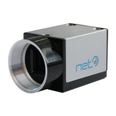
NET s easy to use compact camera with USB 3.0 interface taps the full potential of the latest CMOS
image sensors to set new standards in regard of achievable frames rates and image quality. It supports
24-bit RGB true color while offering a high speed interface to meet the most challenging applications like
multi-camera systems.
Table 1: 3iCube Image Sensors
Model
b/w - NIR - color
Sensor
Image Sensor
Resolution (H*V)
[pixel]
Sensor size
Shutter
Frame rate
[fps]
IC1044CU
CMOS
MT9V032
752 x 480 / WVGA
1/3"
global
86
IC1044BU
CMOS
IC1130CU
CMOS
MT9M131
1280 x 1024 / SXGA
1/3”
rolling
24
IC1130BU
CMOS
MT9M001
1/2"
23
IC4133CU
CMOS
EV76C560
1280 x 1024 / SXGA
1/1.8"
global;
rolling; global
reset
60
IC4133BU
CMOS
IC4133IR
CMOS
EV76C661
1280 x 1024 / SXGA
1/1.8"
IC4203CU
CMOS
EV76C570
1600 x 1200 / UXGA
1/1.8"
global;
rolling; global
reset
47
IC4203BU
CMOS
IC1300CU
CMOS
MT9T001
2048 x 1536 / QXGA
1/2"
rolling with
global reset
12
IC1500CU
CMOS
MT9P001
2592 x 1944 / QSGA
1/2.5"
12
IC1500BU
CMOS
MT9P031
2592 x 1944 / QSGA
1/2.5"
14
IC11000CU
CMOS
MT9J003
3664 x 2748 / WQUXGA
1/2.3"
7.5
IC11000BU
CMOS

7 / 52
Please note that all data and illustrations are subject to error, change and omissions without notice. 3iCube
Operational Manual - Rev. 2.0.1.2
Scope of Delivery
Content
-3iCube is offered as follows
image sensor: see Table 1: 3iCube Image Sensors
versions: industrial (housing) or board-level
mount: C-/CS mount
-CD-ROM including
3iCube iControl viewer software
3iCube USB Driver Windows and Linux (32/64bit)
3iCube Software Development Kit (SDK)
3iCube SDK Manual
3iCube Operational Manual (this document)
Options
-3iCube can be further customized with the following configuration options:
Customized firmware
Real-time processing
Optionally available hardware accessories
The 3iCube camera product does not include any accessories. Other equipment must be provided
separately. System components necessary for using this camera series are listed below:
3iCube camera mounting plate
The mounting plate can be attached to the bottom of the camera and allows the camera to be mounted
on a tripod with a 1/4” screw. The 3iCube camera mounting plate comes with four 6mm M3 screws
(screw acceleration M3 / 2/54 = 0.3Nm / 1/4” = 7Nm)
-CA-Base-Plate-: Order number 05005600xx (*1)
Auxiliary connection cable
This cable allows you to connect digital IO and auxiliary power to the camera. The cable is 5m long with a
header on one side fitting into the 3iCube auxiliary I/O connector.
-CA-iCube-TRIGGER-5m: Standard cable Order number 06087600xx (*1)
-ZY-iCube-TRIGGER-TC-5m: trailer chain cable Order number 06091100xx (*1)

8 / 52
Please note that all data and illustrations are subject to error, change and omissions without notice. 3iCube
Operational Manual - Rev. 2.0.1.2
USB3.0 Cable
This cable is used to connect the camera to host equipment. USB packets (stream and control) are
transmitted via this cable. Please use a USB 3.0 cable that supports USB 3.0 super speed. This product is
able to connect a USB3.0 cable that is equipped with screw lock mechanism.
-CA-USB3/A-microB/screw/2m/Metric: Order number 06092601xx (*1)
-CA-USB3/A-microB/screw/3m/Metric: Order number 06092600xx (*1)
-CA-USB3/A-microB/screw/5m/Metric: Order number 06092602xx (*1)
-CA-USB3/A-microB/screw/8m/Metric: Order number 06092604xx (*1)
Trailer chain USB 3.0 cables are on request.
USB 3.0 Interface Card
This is the interface card to connect to the camera. Usually this card is installed to a PCIe expansion slot
of host PC etc. Please use an USB3.0 interface card with USB 3.0 controller, which support s USB 3.0
super speed.
for PCI Express slot
-IP-PCI-Express-2x-USB3.0: Order number 14002300xx (*1)
-IP-PCI-Express-4x-USB3.0: Order number 14002700xx (*1)
for Express Card slot (for Notebook)
-IP-ExpressCard-2x-USB3.0: Order number 14002500xx (*1)
USB 3.0 Hub
standard hub incl. power supply
-IP-HUB-4x-USB3.0: Order number 14002400xx (*1)
Hub with DIN RAIL Mounting Kit
-IP-ExpressCard-2x-USB3.0: Order number 14002600xx (*1)
*1: Optional part. Contact your NET sales contact for details of option units.

9 / 52
Please note that all data and illustrations are subject to error, change and omissions without notice. 3iCube
Operational Manual - Rev. 2.0.1.2
C-mount lenses and Illumination
NET offers a wide variety of suitable lenses & illumination. Contact your NET sales partner for details.
Optionally available software accessories
-3iCube calibration tool (see chapter Calibration (optional))
Standard Conformity
Legal Notice
The cameras fully implement theUSB3.0 standard.
RoHS II
The product fulfills the requirements of the EU directive RoHS 2011/65/EU in the currently valid version
from 8 June 2011 regarding the restrictive use of certain hazardous materials in electric applications
within the allowable limits.
FCC
This equipment has been tested and found to comply with the limits for a class A digital device,
pursuant to Part 15 of the FCC Rules. These limits are designed to provide reasonable protection against
harmful interference when the equipment is operated in a commercial environment.
This equipment generates, uses, and can radiate radio frequency energy and, if not installed and used in
accordance with the instruction manual, may cause harmful interference to radio communication.
Operation of this equipment in a residential area is likely to cause harmful interference in which case
the user will be required to correct the interference at his own expense.
CE
This apparatus has been certified to meet or exceed the standards for CE compliance per Council
Directives. Pertinent testing documentation is available for verification. This product following the
provision of directive 2004/108/EC.

10 / 52
Please note that all data and illustrations are subject to error, change and omissions without notice. 3iCube
Operational Manual - Rev. 2.0.1.2
Safety Precautions
Before using this product read these safety precautions carefully. Important information is shown in this
Operational Manual to protect users from injuries and property damages and to enable them to use the
product safely and correctly.
Please be sure to thoroughly understand the meanings of the following signs and symbols before reading
the main text that follows, and observe the instructions given herein.
[Definition of Safety Signs]
Notes
*1:“Serious injury” refers to cases of loss of eyesight, wounds, burns (high or low temperature), electric
shock, broken bones, poisoning, etc., which leave after-effects or which requires hospitalization or a long
period of outpatient treatment of cure.
*2:"Light to moderate injuries" refers to injuries, burns, electric shock etc. that do not require
hospitalization or long-term treatment.
*3:"Property damage" refers to cases of extensive damage involving damage to buildings, equipment,
farm animals, pet animals and other belongings.
[Explanation of Safety Symbols]
Safety Signs
Description
WARNING
Indicates a potentially hazardous situation that may result in death or
serious injury (*1) in the event of improper handling.
CAUTION
Indicates a potentially hazardous situation that may result in light to
moderate injuries (*2) or only in property damage (*3) in the event of
improper handling.
Safety Symbols
Description
PROHIBITED
This sign indicates PROHIBITION (Do not).
The content of prohibition is shown by a picture or words beside the symbol.
MANDATORY
This sign indicates MANDATORY ACTION (You are required to do).
The content of action is shown by a picture or words beside the symbol.

11 / 52
Please note that all data and illustrations are subject to error, change and omissions without notice. 3iCube
Operational Manual - Rev. 2.0.1.2
General Handing
WARNING
Unplug
Stop operation immediately when any abnormality or defect occurs.
If abnormal conditions are present, such as smoke, a burning smell, ingress of water
or foreign matter, or if the equipment is dropped or malfunctions, fire or electric
shock may result. Be always sure to disconnect the power cable from the wall
socket at once and contact your dealer.
Do not
wet
Do not use the equipment in locations subject to water splashes. Otherwise, fire
or electric shock may result.
Never pull
apart
Do not disassemble, repair, or modify the equipment. Otherwise, fire or electric
shock may result. For internal repair, inspection or cleaning, contact your sales
representative.
Avoid
Do not place anything on the equipment.
If metallic objects, liquid, or other foreign matter enters the equipment, fire or
electric shock may result.
Avoid
Do not install the equipment in an unstable or inclined location or locations
subject to vibration or impact. Otherwise, the equipment may topple over and
cause personal injury.
Do not touch
During an electrical storm, do not touch the power cable and the connection
cable. Otherwise, an electric shock may result.
Instruction
Use the specified voltage. Use of an unspecified voltage may result in fire or electric
shock.

12 / 52
Please note that all data and illustrations are subject to error, change and omissions without notice. 3iCube
Operational Manual - Rev. 2.0.1.2
Avoid
Do not handle roughly, damaged, fabricated, bent forcefully, pulled, twisted,
bundled, placed under heavy objects or heated the power cable and the
connection cable. Otherwise, fire or electric shock may result.
CAUTION
Instruction
Observe the following when installing the equipment:
Do not cover the equipment with a cloth, etc.
Do not place the equipment in a narrow location where heat is likely to accumulate.
Otherwise, heat will accumulate inside the equipment, possibly resulting in a fire.
Avoid
Do not place the equipment in locations subject to high moisture, oil fumes,
steam, or dust. Otherwise, fire or electric shock may result.
Avoid
Do not install the equipment in locations exposed to direct sunlight or humidity.
Otherwise, the internal temperature of the equipment will rise, which may cause a
fire.
Instruction
Use only specified the power cable and the connection cables. Otherwise, fire or
electric shock may result.
Avoid
Do not give strong impact against the equipment. It may cause the trouble.
Instruction
When performing connection, turn off power. When connecting the power cable
and the connection cable, turn off the equipment power. Otherwise, fire or electric
shock may result.
Avoid
Do not expose the camera head to any intensive light (such as direct sunlight).
Otherwise, its inner image pickup device might get damaged.

13 / 52
Please note that all data and illustrations are subject to error, change and omissions without notice. 3iCube
Operational Manual - Rev. 2.0.1.2
Avoid
Avoid short-circuiting signal output. Otherwise, a malfunction may occur.
Avoid
Avoid giving a strong shock against the camera body. It might cause a breakdown
or damage. If your camera is used in a system where its camera connector is
subjected to strong repetitive shocks, its camera connector is possible to break
down. If you intend to use your camera in such a situation, if possible, bundle and
fix a camera cable in the place near the camera, and do not transmit a shock to the
camera connector.
Usage Notes
Read the documentation
Read the camera documentation before using the camera.
Camera power
Incorrect power input can damage the camera. Do not reverse power polarity. Do not connect or
disconnect other cables when the camera power is on. Use always a USB 3.0 cable as power supply
supported by USB 3.0 port.
Opening the camera
Do not open the camera. Do not let liquid, dust, flammable or metallic material get inside the camera.
Environmental storage conditions
Temperature: -20°C ~ 60°C (- 4°F …. 140°F)
Humidity: 90% or less (no condensation)
Environmental operating conditions
Always use the camera in conditions meeting the specification in this chapter. Do not use the product in
locations where the ambient temperature or humidity exceeds the specifications. In a thermal
challenging environment the customer needs to ensure sufficient heat dissipation with a thermal
connection to the bottom of the camera housing and sufficient airflow.
Non-adequate thermal connection may increase heat induced noise or degrade image quality in other
ways and internal components may be adversely affected up to camera outages due to overheating.

14 / 52
Please note that all data and illustrations are subject to error, change and omissions without notice. 3iCube
Operational Manual - Rev. 2.0.1.2
Temperature
Range
Measurement
Environmental
0°C ~ 45°C (32°F …. 113°F)
close to the camera case
Camera housing
≤ 50°C
at camera case
Humidity
(non-condensing)
Relative
Environmental
20 %–90 %
The conditions for shock and vibrations can be requested from NET.
Maintenance
Turn off power to the equipment and wipe it with a dry cloth. If it becomes severely contaminated,
gently wipe the affected areas with a soft cloth dampened with diluted neutral detergent. Never use
alcohol, benzene, thinner, or other chemicals because such chemicals may damage or discolor the paint
and indications.
Cleaning the sensor window
Avoid cleaning the sensor window if possible. Keep lens cap closed as long as no lens is attached, avoid
touching the sensor. If necessary, clean the sensor window using compressed air. If further cleaning is
required, use lint-free, ESD-safe cloth wiper. Avoid cloth that could generate static charge or that could
scratch the window. The camera should be cleaned in an ESD-safe area. The person performing cleaning
should be earthed.
Connectors
Take care when handling the camera so that no damage can be done to the connectors. Prevent contact
with foreign objects.
Handle carefully
Always transport the camera in its original packaging. Do not drop the equipment or allow it to be
subject to strong impact or vibration, as such action may cause malfunctions. Do not damage the
connection cable, since this may cause wire breakage. If the camera is not in use, attach the lens cap to
the camera to protect the image pickup surface. If the equipment is not to be used for a long duration,
turn off power to the camera for safety.

15 / 52
Please note that all data and illustrations are subject to error, change and omissions without notice. 3iCube
Operational Manual - Rev. 2.0.1.2
Check compatibility of lens
Depending on lens and lighting an image can be reflected as a ghost into the imaging area. This is not a
fault of the camera. Depending on the lens the performance of the camera might not be brought out
fully due to deterioration in resolution and brightness in the peripheral area, aberration and other side
effects. Be sure to check lens and lightning you plan to use for compatibility with your camera. When
installing a lens in the camera make sure that it is not tilted. Use a mounting screw free from defects and
dirt. Otherwise the lens might not be removable from the camera.
Install lenses with a protrusion from bottom of the screw equal or less than 10 mm. If a lens does not
fulfill this condition it might damage the camera when trying to be installed.
10mm or less
C-mount lens Bottom of
the screw
Figure 1: C-Mount Lens
Dropping Frames
Depending on your computer or USB3.0 interface board configurations, images may not be captured
properly (e.g. dropping frames). In this case, change pixel clock setting to lower value.
Occurrence of moiré
If you shoot thin stripe patterns, moiré patterns (interference fringes) may appear. This is not a
malfunction.
Electromagnetic fields
Keep the camera away from strong electromagnetic fields. Avoid static charging and handle the camera
in ESD protected area. If an intense magnetic or electromagnetic field is generated near the camera or
connection cable, noise may be generated on the screen. If this occurs, move the camera or the cable.
Following information is only for EU-member states:
The use of the symbol indicates that this product may not be treated as household waste. By
ensuring this product is disposed correctly, you help to prevent potential negative
consequences for the environment and human health, which could otherwise be caused by
inappropriate waste handling of this product. For more detailed information about the take-
back and recycling of this product, please contact your supplier where you purchased the
product.

16 / 52
Please note that all data and illustrations are subject to error, change and omissions without notice. 3iCube
Operational Manual - Rev. 2.0.1.2
System Requirements
Hardware requirements
-USB 3.0 on board Interface. NET successfully tested USB 3.0 adapters, which use the Renesas
chipset µPD720202 or µPD720200A. Please be sure that you installed the latest USB 3.0 adapter
driver.
-lockable SuperSpeed USB 3.0 cable up to 3m. If you want to use your own USB 3.0 cables, you
have to ensure that the data quality and shielding of the cable is sufficient. Better cable qualities
which go alongside with thicker cable diameter will allow longer distances. We recommend using
the cables that we supply.
-state of the art computer or notebook. (minimum Pentium IV processor with a clock frequency of
at least 1.5 GHz or higher)
Software requirements
iCube iControl–Viewer Software
The iControl software allows you to test the functionalities of the 3iCube camera on your own
application. Apart from controlling the 3iCube camera, you can grab images and save them as jpg, bmp
and tiff files
SynView –Software Development Kit (SDK)
compliancy
USB 3.0 standard
supported image processing
libraries
Adaptive Vision Studio, Halcon, Imaging Library, VisionPro, LabView Vision,
Matlab (and all GenTL consumer)
supported operating systems
Windows XP (32 bit), Windows 7 (32/64 bit), Windows 8 (32/64 bit),
Linux (32/64 bit)
All necessary drivers for Windows and Linux are contained on the CD-ROM. For newer driver versions we
recommend to visit NET´s website www.net-gmbh.com.

17 / 52
Please note that all data and illustrations are subject to error, change and omissions without notice. 3iCube
Operational Manual - Rev. 2.0.1.2
Specifications
Outline Dimensions
Figure 2: 3iCube Housing Dimension
CAD files on request.
(screw acceleration M3 / 2/54 = 0.3Nm / 1/4” = 7Nm)

18 / 52
Please note that all data and illustrations are subject to error, change and omissions without notice. 3iCube
Operational Manual - Rev. 2.0.1.2
Camera Mount
4 mounting screw holes are available on the camera's bottom side to mount the camera on the 3iCube
camera mounting plate, two close to the front side and two close to the back side of the camera as
outlined in Figure 2: 3iCube Housing Dimension. The holes are M3 and screw length of 3mm is allowed.
Lens Mount
C-Mount
All 3iCube models are equipped in the factory with a C-mount adapter (1-inch thread diameter, 32
threads per inch, 17.526 mm flange back) which is adjusted to precisely fulfill the C-mount flange back
distance. Modifications to this adjustment are strongly discouraged since the factory precision is lost.
CS-Mount
The 3iCube camera supports CS-Mount with 12.5 mm flange back after removing the C-Mount adapter
from the camera head. To remove the C-Mount adapter the two 1mm hex-socket screws on the top and
bottom side of the camera's head can be released. After the two screws in the mounting points are
loosened the C-mount adapter can be released. The CS-Mount lens can then be installed directly into the
cameras head. When finished with adjusting fasten the flange back position of the lens with the two
screws again to fix your adjustments.
Interfaces
Table 2: Overview
standard USB 3.0
connector
USB 3.0 micro B with screw locking
USB 3.0 cable
3 twisted pair (shielded), 1 pair unshielded, cable full shielded, super speed
(for up to 5Gbit/s)
USB 3.0 cable length
up to 3m (longer cables on request by NET)
auxiliary cable
connector
8 pin connector,
digital input/output
external trigger input (Line0) = opto coupled (open collector)
external strobe output (Line1) = opto coupled (open collector)
3x GPIO (optional)

19 / 52
Please note that all data and illustrations are subject to error, change and omissions without notice. 3iCube
Operational Manual - Rev. 2.0.1.2
Note:
Please heck if the power supply of the camera is switched off before plugging in or pulling out the I/O
connector. Always use a USB 3.0 cable with a lock screw and secure the camera cable as close as possible
to the camera body in order to avoid physical damage to the camera connector and electronics.
Connector Pin Assignment
Figure 3: Camera rear view with AUX pin order

20 / 52
Please note that all data and illustrations are subject to error, change and omissions without notice. 3iCube
Operational Manual - Rev. 2.0.1.2
Micro B USB 3.0 Connector
The camera uses the USB 3.0 interface and is fully compatible with the USB 3.0 standard.
Table 3: USB 3.0 Interface Connector micro B
Pin No.
I/O
Signal
Function
1
-
VBUS
Power
2
I/O
D-
USB 2.0 differential pair
3
I/O
D+
USB 2.0 differential pair
4
I/O
ID
DPWR
5
-
GND
Ground
6
I/O
SSTX-
Super speed transmitter differential pair
7
I/O
SSTX+
Super speed transmitter differential pair
8
-
GND
Ground for signal
9
I/O
SSRX-
Super speed receiver differential pair
10
I/O
SSRX+
Super speed receiver differential pair
shell
-
GND
shield
Auxiliary I/O Connector
The camera has an 8pin connector to connect digital IO
Table 4: Auxiliary I/O Connector pin assignment
Pin No.
I/O
Signal
Function
1
I
LINE 0
Trigger Input
2
I
LINE 0 GND
Trigger Input GND
3
O
LINE 1
Strobe 1 Output
4
O
LINE 1 GND
Strobe 1 Output GND
5
I/O
GPIO 1
(optional)
6
I/O
GPIO 2
(optional)
7
I/O
GPIO 3
(optional)
8
-
GND
Power GND
Table of contents
Other NET Digital Camera manuals
