Net2Edge PB-TDM1-CONTRA User manual

Contra-Directional G.703 to IP
Converter
Quick Setup Guide
33604 Rev. A

Transition Networks Contra Converter Quick Setup Guide
Trademarks
All trademarks and registered trademarks are the property of their respective owners.
Copyright Notice/Restrictions
Copyright © 2014 Transition Networks
All rights reserved.
No part of this work may be reproduced or used in any form or by any means (graphic, electronic or
mechanical) without written permission from Transition Networks.
The information contained herein is confidential property of Transition Networks, Inc. The use,
copying, transfer or disclosure of such information is prohibited except by express written agreement
with Transition Networks, Inc.
Printed in the U.S.A.
PB-TDM1-CONTRA-W-AC Contra-Directional G.703 to IP Converter
Quick Setup Guide, 33604 Rev. A
Contact Information
Transition Networks
10900 Red Circle Drive
Minnetonka, MN 55343 USA
Tel: 952- 941-7600 or 1-800-526-9267
Fax: 952-941-2322
Revision History
Rev Date Description
A
11/24/14
Initial release.
See the related Install Guide manual for Cautions, Warnings, and Important Safety Notice.
33604 Rev. A www.transition.com Page 2 of 72

Transition Networks Contra Converter Quick Setup Guide
Contents
Introduction..............................................................................................................................................5
Applications.........................................................................................................................................5
Initial Configuration / Setup.....................................................................................................................6
1. Local IP Address/Subnet Mask/Default Gateway.......................................................................6
2. Logical Link Configuration...........................................................................................................7
3. G.703 Port...................................................................................................................................8
4. Clocking.......................................................................................................................................9
5. Additional Configuration............................................................................................................10
Startup Screen ......................................................................................................................................10
Configuration Menu...............................................................................................................................11
Configuration > CES > Port Settings ................................................................................................11
Configuration > CES > Link > Settings .............................................................................................12
Configuration > CES > Link > VLAN.................................................................................................14
Configuration > CES > Link > Automatic Jitter Adjust ......................................................................16
Configuration > CES > Link > Schedule ...........................................................................................18
Configuration > CES > Protocol........................................................................................................19
Configuration > CES > Multicast.......................................................................................................21
Configuration > CES > Event Reporting...........................................................................................22
Configuration > CES > Clock Priorities.............................................................................................23
Monitoring..............................................................................................................................................24
Monitor > System Information...........................................................................................................24
Monitor > Log....................................................................................................................................24
Monitor > CES > Ports > State..........................................................................................................25
Monitor > CES > Ports > Loops........................................................................................................26
Monitor > CES > Links > Summary...................................................................................................27
Monitor > CES > Links > Detailed.....................................................................................................28
Monitor > CES > Report....................................................................................................................31
Monitor > CES > Calls.......................................................................................................................32
Monitor > CES > Clocking > Summary.............................................................................................33
CES Clocking Status.........................................................................................................................33
CES Clocking Streams......................................................................................................................33
Monitor > CES > Clocking > History > Table....................................................................................35
Monitor > CES > Clocking > History > Graph...................................................................................36
Monitor > CES > Temperature..........................................................................................................38
Diagnostics............................................................................................................................................39
Diagnostics > VeriPHY......................................................................................................................39
Maintenance..........................................................................................................................................39
Maintenance > Software > Image Select..........................................................................................39
Maintenance > Configuration > Backup Binary ................................................................................40
Maintenance > Configuration > Restore Binary................................................................................40
CLI Command Summary.......................................................................................................................41
Login and Help (?) Commands.........................................................................................................41
CES Commands ...................................................................................................................................42
List the command groups using the Help command.........................................................................42
List the CES commands....................................................................................................................43
CES Command Groups ....................................................................................................................43
CES Port Commands....................................................................................................................44
CES Link Commands....................................................................................................................46
CES LAN Commands ...................................................................................................................55
CES Clock Commands .................................................................................................................58
CES Status / Event Commands....................................................................................................60
33604 Rev. A www.transition.com Page 3 of 72

Transition Networks Contra Converter Quick Setup Guide
CES Debug Commands................................................................................................................66
Related CLI Commands....................................................................................................................71
33604 Rev. A www.transition.com Page 4 of 72
Transition Networks Contra Converter Quick Setup Guide
Introduction
The Contra Converter supplies a clock-locked 64K G.703 circuit over Ethernet, IP, or MPLS networks.
The following sections detail the Contra Converter applications, IP address setup, Logical Link setup,
G.703 port config, Clock config, some additional configuration, and Monitoring, Diagnostics, and
Maintenance. See the related Install Guide for features, models, specifications and documentation
Applications
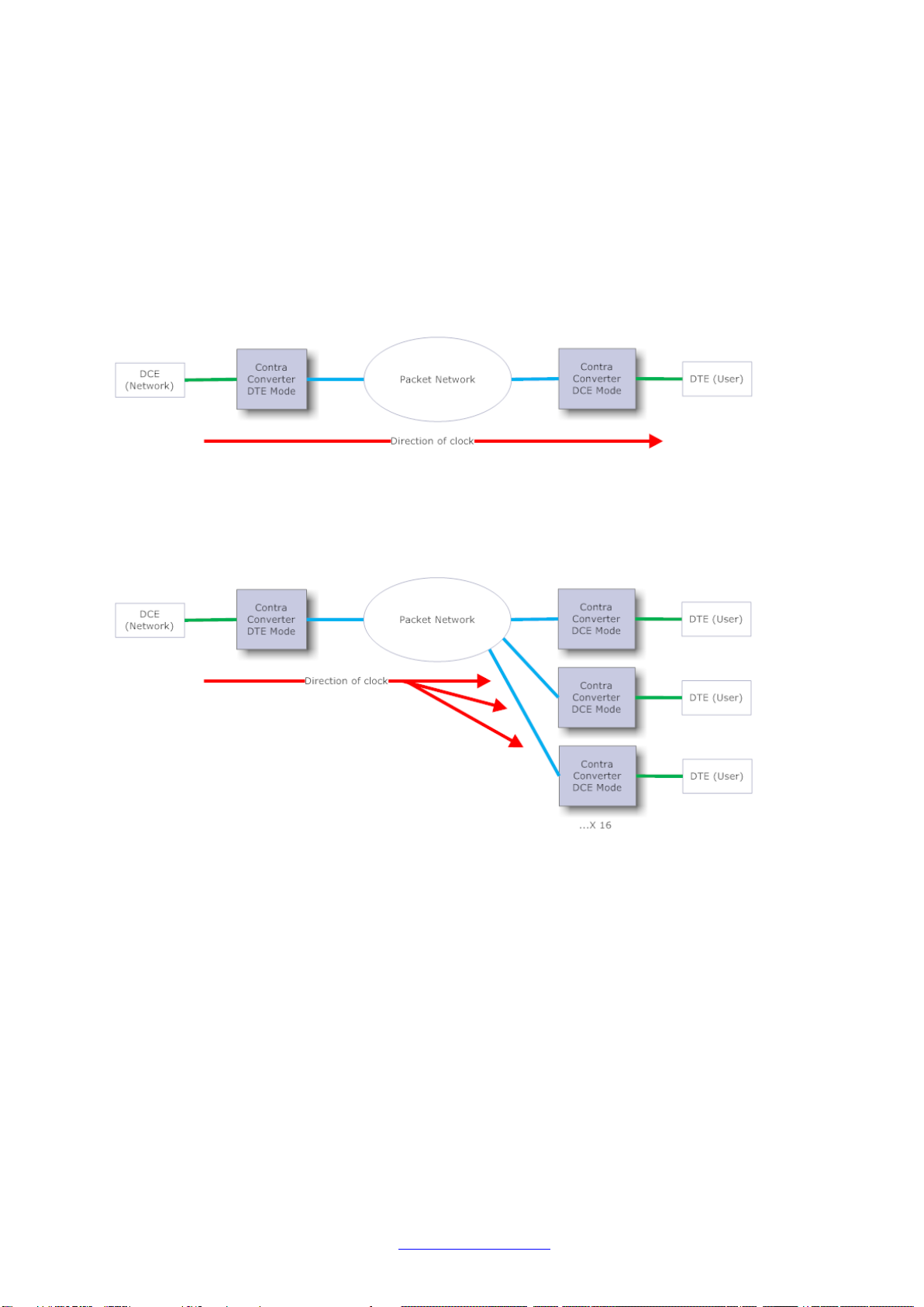
Contra Converters need to be configured in order to communicate and work with each other.
A typical, two device, Point-to-point system might look as below:
This system involves two Contra Converters, and clocked data is passed from the DCE Network
across the system to the DTE User via the packet network.
There are also situations where Point-to-Multipoint operation may be required. In this instance, up
to 16 remote endpoints may be included:
In this configuration, data is split from one Contra Converter to the remote destination Contra
Converters. In this example the DTE Contra Converter would be configured with multiple Logical
Links; each one pointing to the IP Address of an individual remote Contra Converter. The remote
units are each configured in just the same way as in the Point-to-point application example.
Here the separation of the data between the endpoints and the interleaving of the data into the
central unit happen automatically.
In order to create a 64K circuit between two Contra Converters via a packet network, there are four
key settings which must be configured for any application. These are:
1. Local IP Address/Subnet Mask/Default Gateway
2. Logical Link Configuration
3. G.703 Port
4. Clocking
33604 Rev. A www.transition.com Page 5 of 72

Transition Networks Contra Converter Quick Setup Guide
Initial Configuration / Setup
1. Local IP Address/Subnet Mask/Default Gateway
Contra Converter can initially be connected to using either CLI or via web browser using the default
IP settings. Please see the Contra Converter Install Guide manual for details on how to connect via
one of these methods.
If connected via the Web GUI, go to Configuration >System >IP and configure the details to match
those provided by your Network Administrator.
Click Save when this is complete.
If connected via the CLI, the command for setting the IP details is as follows:
ip setup [<ip_addr>] [<ip_mask>] [<ip_router>]
The first option is the IP Address, the second is the Subnet Mask and the third is the Default
Gateway. Type ? for a full list of commands. Please see the related CLI Reference manual for more
information on using the CLI.
33604 Rev. A www.transition.com Page 6 of 72
Transition Networks Contra Converter Quick Setup Guide
2. Logical Link Configuration
The Logical Link is the data connection between the two devices which will carry the 64K traffic
across the packet network. The Contra Converter’s Logical Link must be configured with the remote
Converter’s IP address in order for the traffic to be sent there. The number of TDM frames per
packet and Jitter Buffer Length can also be configured here.
Via the Web GUI, the Logical Link settings can be found in Configuration >CES >Link >Settings
Configure Link 1 with a Name, single Remote IP (the IP Address of the remote Contra Converter),
then click Save at the bottom of the page.
Note that the Frames per Packet and Jitter Buffer Length settings both default to 1, which gives the
absolute minimum latency across the link. These settings can be changed if required in order to
decrease bandwidth overheads.
If using the CLI, the command to enable the Logical Link is:
CES link setup remote 1 both [<remoteip>]
The <remoteip> element should be the IP address of the remote Contra Converter, or its publicly
visible gateway address. A name for the Link can optionally be set using this command:
CES link setup name 1 [<name>]
When the device is connected to two or more remote Contra Converters in a Point-to-Multipoint
application, a second Logical Link can be added here in the same way. The IP Addresses of the
destination remote Contra Converter should be configured on the relevant Link.
33604 Rev. A www.transition.com Page 7 of 72

Transition Networks Contra Converter Quick Setup Guide
3. G.703 Port
This setting can be found via the Web GUI in Configuration >CES > Port Settings.
The G.703 Contra port must be configured as either DCE or DTE. DCE mode is Network presentation.
In this mode, Contra Converter’s G.703 port is acting as a Network which a User (DTE) presentation
device will connect to. Clocking is provided from Contra Converter to the DTE device.
DTE mode is User presentation and should be used when Contra Converter is connected to a
Network interface such as a Leased Line. Clocking is provided from the DCE Network into the DTE
Contra Converter.
Select the appropriate Port Type and click Save.
From the CLI, the command to select DTE or DCE mode is:
ces port setup 1 [dce|dte]
33604 Rev. A www.transition.com Page 8 of 72
Transition Networks Contra Converter Quick Setup Guide
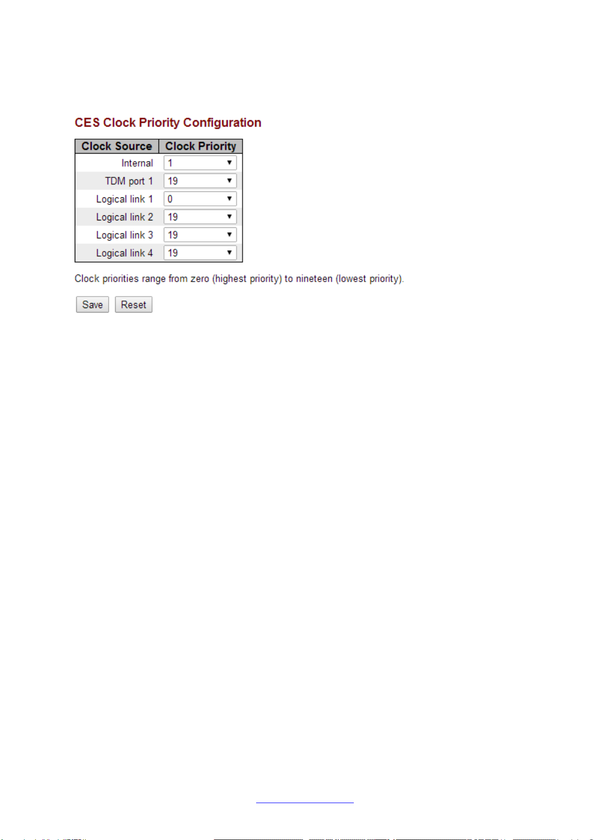
4. Clocking
From the Web GUI, the Clocking configuration can be found in Configuration >CES >Clock Priorities.
For any synchronous-based system, it is important that the devices follow a common clock
reference. Typically, a DCE device or network provides clock for a DTE device to use. The Contra
Converter can be configured to clock from its G.703 port, its Logical Link, or use its own internal
reference.
Contra Converter is able to dynamically switch between clock sources as they are made available.
The priority window allows a priority to be set against each clock source. The highest available
priority value is 0, while the lowest is 19. Assign values to the sources which will be used; the unused
ports can be left set at 19.
Note that by default, the Internal source is set to 0 (highest priority).
From the CLI, the commands needed to set up the clocking priorities are:
CES clock priority internal <priority>
CES clock priority port 1 <priority>
CES clock priority stream 1 <priority>
where:
<priority> is the assigned priority value 0-19.
“port 1” is the G.703 port,
“stream 1” is the Logical Link between the devices.
33604 Rev. A www.transition.com Page 9 of 72

Transition Networks Contra Converter Quick Setup Guide
5. Additional Configuration
The PacketBand+ Web User Guide documents the PacketBand+ family Web GUI operation. Functions
specific to the Contra Converter are described below. See the PacketBand+ Web User Guide manual
for information not covered here.
Startup Screen
At initial GUI startup, the Port State Overview page displays with the current port state and status.
From this page you can navigate to the Contra Converter main menus and sub-menus.
33604 Rev. A www.transition.com Page 10 of 72
Transition Networks Contra Converter Quick Setup Guide
Configuration Menu
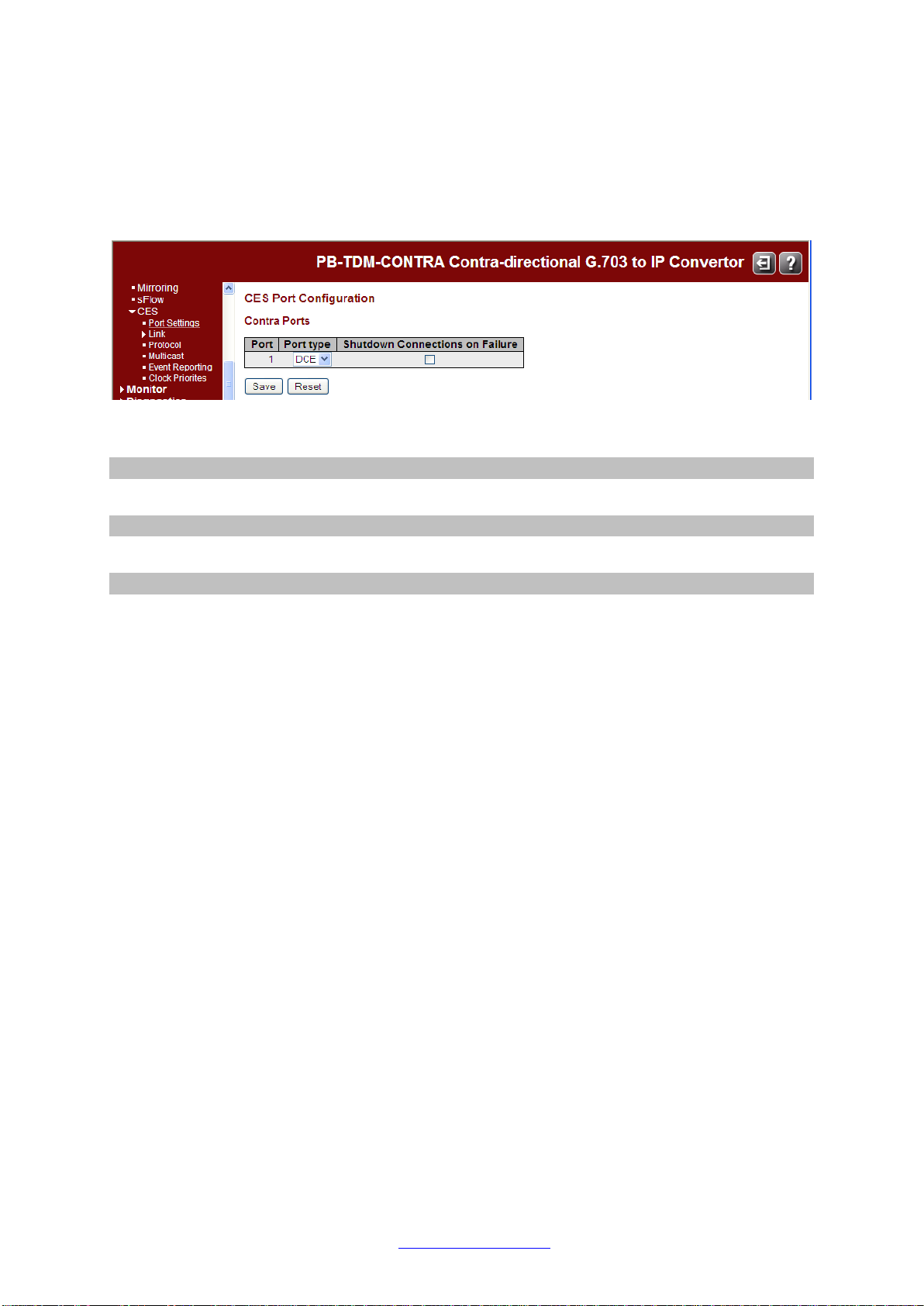
Navigate to Configuration > CES > Port Settings to configure the Contra Converter’s TDM ports.
Configuration > CES > Port Settings
This page shows the configuration of the TDM ports.
The Contra Ports parameters are described below.
Port
The TDM port number.
Port type
The type of the Port (DTE - Terminal or DCE - Network).
Shutdown Connections on Failure
Check the checkbox to elect to close connections when a failure occurs.
Buttons
Save: Click to save the new configuration for the Port(s).
Reset: Click to reset the new configuration back to the current configuration.
33604 Rev. A www.transition.com Page 11 of 72
Transition Networks Contra Converter Quick Setup Guide
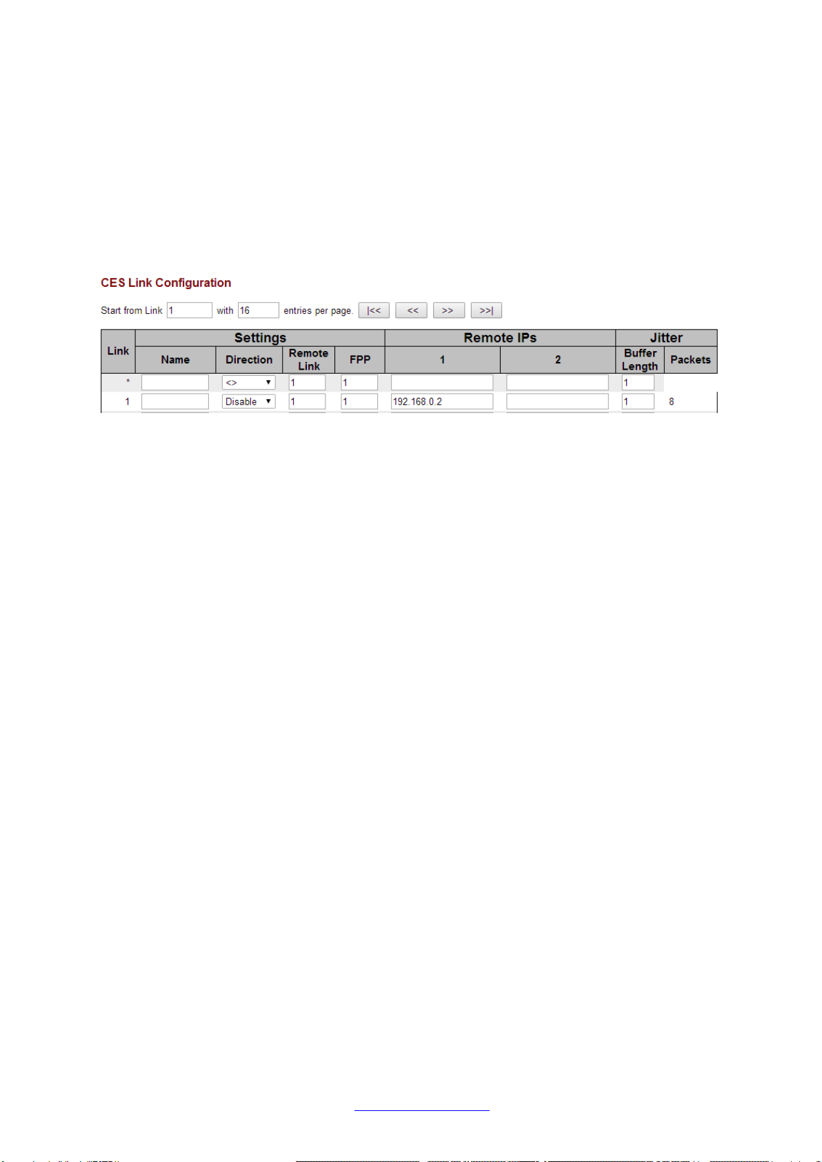
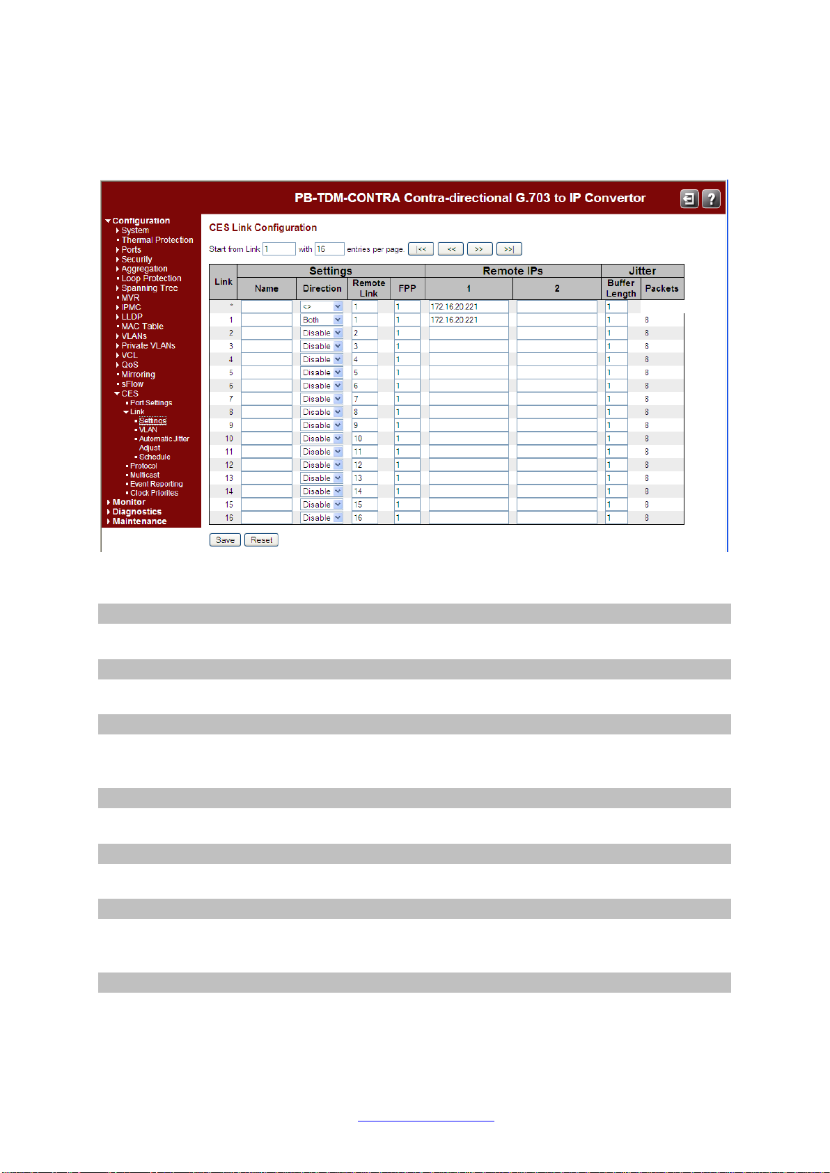
Configuration > CES > Link > Settings
This page shows the Configuration for all Logical Links.
The displayed items are:
Link
The logical link number.
Name
The optional name the user can configure for the logical link.
Direction
This allows the Link to be configured for Receive only, Transmit only, or allow both directions.
The default is Disabled.
Remote Link
The Link number for the Remote Link.
FPP (Frames Per Packet)
The number of frames per packet on the link.
Remote IP 1
The IP address of the remote end of the link (can be IPv4 or IPv6). This may be a multicast
group address when the direction is transmit only.
Remote IP 2
Optional second Remote IP address (can be IPv4 or IPv6). Only allowed when the direction is
Receive only.
33604 Rev. A www.transition.com Page 12 of 72

Transition Networks Contra Converter Quick Setup Guide
Jitter Buffer Length
The Length of the Jitter Buffer. The default is 1.
Jitter Packets
Number of Jitter Packets (calculated from the Frames Per Packet and the Jitter Buffer
Length).
Start from Link
The start Link number for the list of Links to be displayed on the page.
entries per page
The number of Link entries to be listed on the page.
Buttons
Save: Click to save changes.
Reset: Click to undo any changes made locally and revert to previously saved values.
|<<: Click to display the first page. NB Unsaved changes on the current page will be lost.
<<: Click to display the previous page. NB Unsaved changes on the current page will be lost.
>>: Click to display the next page. NB Unsaved changes on the current page will be lost.
>>|: Click to display the last page. NB Unsaved changes on the current page will be lost.
33604 Rev. A www.transition.com Page 13 of 72

Transition Networks Contra Converter Quick Setup Guide
Configuration > CES > Link > VLAN
This page lets you configure QOS and VLAN for all Logical Links.
The displayed items are:
Link
The logical link number.
Settings Name
The optional name the user can configure for the logical link.
QOS Type
Type of Quality of Service for each Link (Diffserv or Type of Service).
QOS Value
The Quality of Service Value for each Link.
For Diffserv, this value is a Diffserv CodePoint (DSCP) in the range 0 - 63.
For Type of Service, this value is in the range 0 - 255.
VLAN Tagging State
Enable or Disable VLAN Tagging per each Link. Note: If any logical link has VLAN tagging
enabled, then the ingress Ethernet port(s) must be configured in a VLAN aware mode in order
to allow VLAN tagged address resolution frames to be recognised and processed.
VLAN Tagging Identifier
The VLAN Id for each Link.
VLAN Tagging Priority
VLAN Tagging Priority value for each Link. The default is priority 0.
33604 Rev. A www.transition.com Page 14 of 72

Transition Networks Contra Converter Quick Setup Guide
Buttons
Save: Click to save changes.
Reset: Click to undo any changes made locally and revert to previously saved values.
|<<: Click to display the first page. NB Unsaved changes on the current page will be lost.
<<: Click to display the previous page. NB Unsaved changes on the current page will be lost.
>>: Click to display the next page. NB Unsaved changes on the current page will be lost.
>>|: Click to display the last page. NB Unsaved changes on the current page will be lost.
33604 Rev. A www.transition.com Page 15 of 72

Transition Networks Contra Converter Quick Setup Guide
Configuration > CES > Link > Automatic Jitter Adjust
This page displays the current CES auomatic jitter buffer adjustment configuration for logical links and
allows the configuration to be modified.
The parameters are described below.
Link
The logical link number.
Mode
The mode in which automatic jitter buffer adjustment is to be run. Choose one of:
•None - No automatic adjustment of the jitter buffer will be carried out for this logical
link.
•Always on - Automatic jitter buffer adjustment is carried out periodically for this
logical link while it is active.
•Schedule - Automatic jitter buffer adjustment is carried out while this link is active
when a schedule stop time is reached.
•Once only - Automatic jitter buffer adjustment is carried out once after this logical link
becomes active.
Adjust after
In 'Always on' and 'Once only' modes, how long to wait in minutes before doing any jitter
buffer adjustment once the logical link has become active.
Schedule / Day / Start
In 'Schedule' mode, the time of day to start doing periodic jitter buffer adjustment when the
logical link is active. The first field is hours, the second is minutes.
Schedule / Day / Stop
In 'Schedule' mode, the time of day to stop doing periodic jitter buffer adjustment when the
logical link is active. The first field is hours, the second is minutes.
33604 Rev. A www.transition.com Page 16 of 72

Transition Networks Contra Converter Quick Setup Guide
Buttons
Save: Click to save changes.
Reset: Click to undo any changes made locally and revert to previously saved values.
|<<: Click to display the first page. NB Unsaved changes on the current page will be lost.
<<: Click to display the previous page. NB Unsaved changes on the current page will be lost.
>>: Click to display the next page. NB Unsaved changes on the current page will be lost.
>>|: Click to display the last page. NB Unsaved changes on the current page will be lost.
33604 Rev. A www.transition.com Page 17 of 72

Transition Networks Contra Converter Quick Setup Guide
Configuration > CES > Link > Schedule
This page displays the current CES schedule configuration for logical links and allows the
configuration to be modified. Schedules are used to control when a logical link will be active. Note that
other factors may also affect making the link active (e.g., network connectivity and TDM port
availability).
The parameters are described below.
Link
The logical link number.
Schedule?
Whether to enable scheduling. Choose one of:
•Always on - No scheduling.
•Schedule - The logical link is only active during the specified schedule times.
Schedule / Day / Start
In 'Schedule' mode, the time of day to activate the logical link. The first field is hours, the
second is minutes.
Schedule / Day / Stop
In 'Schedule' mode, the time of day to decativate the logical link. The first field is hours, the
second is minutes.
Buttons
Save: Click to save changes.
Reset: Click to undo any changes made locally and revert to previously saved values.
|<<: Click to display the first page. NB Unsaved changes on the current page will be lost.
<<: Click to display the previous page. NB Unsaved changes on the current page will be lost.
>>: Click to display the next page. NB Unsaved changes on the current page will be lost.
>>|: Click to display the last page. NB Unsaved changes on the current page will be lost.
33604 Rev. A www.transition.com Page 18 of 72
Transition Networks Contra Converter Quick Setup Guide
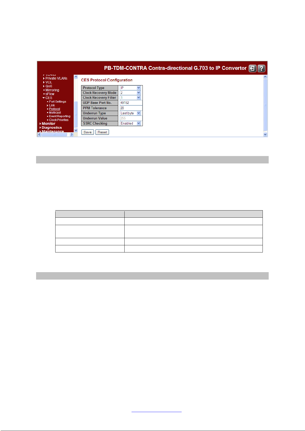
Configuration > CES > Protocol
This page shows the Protocol Configuration of the LAN ports.
The displayed items are:
Protocol Type
The protocol type used for CES frames (UDP/RTP, IP, or Ethernet). Changing this setting
requires a reboot. Different IP networks will often support different operating protocol.
PacketBand can be configured to operate with four different network types. Please consult a
Network Administrator if you are unsure about the protocol of an IP network. In some
situations, the default setting on PacketBand will interface with a different network type and
not require alteration. The four different options are:
Protocol
Description
Pseudo-wire over IP
Standard layer 3 Internet Protocol
Pseudo-wire over IP
including UDP/RTP
RTP IP + UDP + RTP for UDP port number mapping
Pseudo-wire over MPLS
MPLS for multi-protocol packet switched networks
Pseudo-wire over Ethernet
Standard layer 2 Ethernet Protocol
Some protocol types will make new options available elsewhere in the PacketBand
configuration menus. These are explained later in this manual.
Clock Recovery Mode
Clock Recovery Mode (1to 3). PacketBand has three modes which can be used. The clock
recovery modes have different characteristics, and are each suited to specific types of IP
network. Please read through the information below to make sure that the correct Clock
Recovery Mode is selected for the IP network in use. Using the correct Clock Recovery Mode
will optimize clock recovery performance for a system.
Mode 1: Known as Adaptive mode. It is best suited to fairly heavily loaded, busy networks.
This mode will quickly adapt to network conditions and adjust the Derived Clock Offset (DCO)
regularly to adapt to network conditions. This mode can be thought of as the least fastidious.
Mode 2: Known as Enhanced Adaptive mode. It is suited to high quality, low user networks.
If prioritization via QoS or VLAN is in use as well, this mode will particularly excel at clock
recovery. The DCO is adjusted much less frequently when using this protocol in comparison
to Mode 1. This makes the clocking more stable, and clock changes are less drastic. There
are some precautions to take when using mode 2:
•During extensive profiling and testing using Mode 2 it has been proved that this clock
system provides exceptional performance on the majority of "real” networks. However, it
has also been discovered that network simulators and network simulation packages do not
33604 Rev. A www.transition.com Page 19 of 72

Transition Networks Contra Converter Quick Setup Guide
provide a true representation of the network and do not generate the specific packet profile
required by Mode 2. Users of simulator and simulation packages should be aware that
Clock Mode 2 may not be suitable.
•It is recommended that the Frames per Packet value on each Logical Link be set to a
value of less than 40 when using mode 2 to ensure optimum clock recovery performance.
Mode 3: Known as Adaptive Frequency. It is suited to low quality networks, and networks
where changes to the clock recovery offset have a greater impact on the system devices.
The DCO value is changed very infrequently. Please consult the below table for information
on how long PacketBand takes to go into each clock recovery state using the different modes
available.
Clock
Recovery
Mode
Time to go to
Acquiring state (s) Time to go to
Acquired state (s)
1
20
50
2
200
800
3
-1
300
All times shown are approximate, and can be affected by the Clock Recovery Filter, Jitter
Buffer, Frames per Packet and Network conditions on a system.
Clock Recovery Filter
Clock Recovery filter (1or 2). The Clock Recovery Filter is used to set the size of the window
which PacketBand uses to look for clocking information received from the master
PacketBand. Using Filter 2 narrows the search window, so that clocking information can be
found more quickly and the unit will enter the Acquired state faster. The downside to using
Filter 2 is that an increase in jitter or network latency will have a greater effect on PacketBand.
It is recommended that Filter 2 is only used on high quality IP networks with very low Jitter
and a latency of 10ms or less.
UDP Base Port No.
Base Port Number for the UDP. The first logical link uses this port number. The second
logical link uses this port number plus one, the third uses this port number plus two, etc.
For logical links that are not idle, changes take effect the next time the link is restarted.
PPM Tolerance
Clock recovery tolerance in parts per million. The PPM tolerance option can be used to offset
the frequency of PacketBand's on-board oscillator. This can be used for fine tuning
clock recovery within a system. This is an advanced feature, and should not be adjusted
without a full understanding of the consequences. Please contact Transition Networks if fine
clocking adjustments are required.
Underrun Type
Underrun type (Fixed Byte or Last Byte). Specifies what value to use for a TDM timeslot
when an underrun occurs. Fixed Byte uses a specified value, Last Byte uses the last known
value. For logical links that are not idle, changes take effect the next time the link is restarted.
Underrun Byte Value
Underrun Byte Value if Fixed Byte selected. When the underrun type is Fixed Byte, this is the
value that will be used for a TDM timeslot when an underrun occurs. For logical links that are
not idle, changes take effect the next time the link is restarted.
33604 Rev. A www.transition.com Page 20 of 72
Table of contents
Other Net2Edge Media Converter manuals


