Net2Edge LIB-306 User manual

LIB-306 Carrier Ethernet (CE)
Network Interface Device (NID)
Install Guide
Rev. D

Net2Edge LIB-306 Install Guide
Install Guide Rev. D www.net2edge.com Page 2 of 25
Safety Warnings and Cautions
These products are not intended for use in life support products where failure of a product could reasonably be
expected to result in death or personal injury. Anyone using this product in such an application without express written
consent of an officer of Net2Edge does so at their own risk, and agrees to fully indemnify Net2Edge for any damages
that may result from such use or sale.
Attention: this product, like all electronic products, uses semiconductors that can be damaged by ESD
(electrostatic discarge). Always observe appropriate precautions when handling.
Warning: Potential for damage to equipment or personal injury.
Warning: Risk of Electrical Shock
Functional grounding point
Protective grounding point
Special considerations
LIB-306 Install Guide -
Record of Revisions
Rev
Date
Description of Changes
A
12th December 2014
Initial release for LIB-306 software v 2.0.x.
B
1st May 2015
Updated to v 2.1.3 which adds DDMI, HQoS, JSON, LLDP-MED, MEP BFD, MPLS-TP,
PFC, Traffic Test Loop, UDLD, and Y.1564 support.
C
25th September 2015
Update the Rack Mount Installation information.
D
26th January 2017
Re-Branded Manual
Trademark notice
All trademarks and registered trademarks are the property of their respective owners. All other products or
service names used in this publication are for identification purposes only, and may be trademarks or
registered trademarks of their respective companies. All other trademarks or registered trademarks
mentioned herein are the property of their respective holders.
Copyright restrictions
© 2017, Net2Edge Ltd. All rights reserved. No part of this work may be reproduced or used in any form or
by any means (graphic, electronic, or mechanical) without written permission from Net2Edge.
Address comments on this product or manual to:
Net2Edge
Kulite House, Stroudley Road,
Basingstoke, RG24 8UG, UK.
Tel: +44 345 0130030
E-Mail: support@net2edge.com

Net2Edge LIB-306 Install Guide
Install Guide Rev. D www.net2edge.com Page 3 of 25
Table of Contents
Safety Warnings and Cautions......................................................................................................................2
1. Introduction.................................................................................................................................................4
Product Description.......................................................................................................................................4
Models...........................................................................................................................................................4
Applications...................................................................................................................................................4
Features........................................................................................................................................................6
Specifications................................................................................................................................................7
Related Manuals and Help............................................................................................................................7
2. Installation...................................................................................................................................................8
Unpacking / Package Contents.....................................................................................................................8
Install Cautions and Warnings......................................................................................................................8
Installation Location ......................................................................................................................................8
Rack Mount Installation.............................................................................................................................8
Grounding and Wiring Recommendations....................................................................................................9
Back Panel....................................................................................................................................................9
Front Panel..................................................................................................................................................10
Connecting Power.......................................................................................................................................12
Installing SFP Modules and Fiber Cables...................................................................................................13
Installing SFPs.........................................................................................................................................13
Installing Copper Cables.............................................................................................................................14
Copper Cable Configuration....................................................................................................................14
Connecting Ethernet Cables ...................................................................................................................14
Connecting Via the Serial CONSOLE / CLI................................................................................................15
Connecting Via the MGMT Port / Web GUI................................................................................................15
Factory Defaults..........................................................................................................................................16
Login using PuTTY Terminal Emulator Software........................................................................................16
Login Using Telnet......................................................................................................................................17
Login Using the Web Interface....................................................................................................................17
Re-Access the Web GUI via CLI Commands.............................................................................................17
Switching MGMT / PORT 1 Modes.............................................................................................................18
Configure the Default Management Port as a Data Port ........................................................................18
Product Registration....................................................................................................................................19
3. Troubleshooting .......................................................................................................................................19
4. Service, Warranty and Tech Support......................................................................................................22
Contact Us ..................................................................................................................................................22
Warranty......................................................................................................................................................22
One-Year Limited Hardware Warranty ...........................................................................................22
Return Authorization .........................................................................................................................22
Return Instructions.............................................................................................................................22

Net2Edge LIB-306 Install Guide
Install Guide Rev. D www.net2edge.com Page 4 of 25
European Regulations.............................................................................................................................24
Electrical Safety Warnings..........................................................................................................................25
1. Introduction
Product Description
Net2Edge’s managed LIB-306 NID provides advanced packet performance metering and service creation
aimed directly at customer premises and cell sites. The LIB-306 is optimized for business Ethernet and
mobile backhaul deployments.
The LIB-306 is a multi-service NID that provides SLA assurance and advanced fault management that is
MEF CE2.0 compliant. IEEE 802.1ag Service OAM, ITU Y.1731 Performance Monitoring and IEEE 802.3ah
Link OAM are standard features.
The LIB-306 supports advanced features such as IPv6 and IPv4, VLANs, QoS, bandwidth allocation, ring
protection, jumbo frames and numerous security features. The LIB-306 can be managed and provisioned
with Net2Edge Converge™EMS or via Web, CLI and SNMP (v1, v2c & v3). The LIB-306 supports
SSL/SSH, RADIUS, TACACS+, Management VLAN and ACL rules.
The LIB-306 offers AC or DC power inputs for operation in a variety of environments. The SFP ports are
triple speed and support 100Mbps, 1000Mbps or SGMII SFPs. CWDM and Bi-Di SFPs are also supported,
allowing for flexible network architectures.
Models
The LIB-306 models are described below.
Model
Description
LIB-306-24
2xTP 4xSFP NID: Two 10/100/1000Mbps RJ45 ports with four 100/1000Mbps SFP
ports. Includes IEEE 1588v2 with RFC 2544 Traffic Generation.
LIB-306-42
4xTP 2xSFP NID: Four 10/100/1000Mbps RJ45 ports with two 100/1000Mbps SFP
ports. Includes IEEE 1588v2 with RFC 2544 Traffic Generation.
Applications
The LIB-306 is designed to support a wide range of MEF-based Carrier Ethernet services to include:
MEF CE 2.0 Certified Services (E-LINE, E-LAN, E-ACCESS, E-TREE)
Mobile Backhaul
Business Ethernet
Fiber to the Premise (FTTP)
SLA Enforcement Performance Statistics
Migration to Packet Networks
QoS for Differentiated Services
Several LIB-306 application examples are provided below.

Net2Edge LIB-306 Install Guide
Install Guide Rev. D www.net2edge.com Page 5 of 25
CE Services Example
Cloud Services Example
E-LAN Services Example
E-Line Services Example

Net2Edge LIB-306 Install Guide
Install Guide Rev. D www.net2edge.com Page 6 of 25
Features
Two/four 10/100/1000Mbps Base–T ports. Four/two 100/1000Mbps SFP ports. Any port can be
network (NNI) or client (UNI).
Two of the SFP ports support a proprietary 2.5Gbps mode.
TP ports support IEEE 802.3az Energy Efficient Ethernet for power saving.
Full bandwidth 1000Mbps switching, non blocking.
SNMP v1, v2c, and v3.
IPv6 and IPv4 support.
VLAN (802.1Q) Q-in-Q (C-Tag / S-Tag).
RMON and Syslog.
OAM Support: IEEE 802.3ah Link OAM, IEEE 802.1ag Service OAM, ITU-T Y.1731 Performance
Monitoring, and MEF E-LMI.
Loop Protection: ITU G.8032 and IEEE RSTP, MSTP.
G.8031 Linear Protection switching
IEEE 1588v2 PTP (Precision Time Protocol).
DC or AC power input (12VDC Barrel connector or 2-Pin, 21-60VDC Terminal block).
Jumbo Frame Support (10240 bytes maximum).
Wire speed loopbacks.
RFC 2544 Traffic Generation and Reports.
Last Gasp/Dying Gasp notification via SNMP trap. Monitor Rx and Tx Dying Gasp for each port.
SNMP traps configurable: System (Warm Start, Cold Start); Interface (Link Up. Link Down, LLDP);
AAA (Authentication Fail); Switch (STP, RMON).
Alarm inputs/outputs: RJ-45 connector with 2-IN and 2-OUT, 10-30VDC, 40mA maximum; optically
isolated from main board. Alarm indications via Syslog and SNMP.
E-LINE (EPL and EVPL) / E-LAN (EP-LAN and EVP-LAN) / E-ACCESS (ACCESS EPL and EVPL)
/ E-TREE (EP-TREE and EVP-TREE).
UNI or NNI configuration.
TOS (Type of Service) and Diffserv (Differentiated services).
QoS (802.1p Quality of Service): 8 queues; strict priority and DWRR, shaping, policing, P-bit and
DSCP.
Management via Industry standard CLI, Web, SSH/SSL & SNMP (v1, v2c, v3).
Port configuration, status, statistics, and monitoring.
RADIUS, TACACS+ and ACL.
Remote backup / restore configuration / firmware upgrades.
L2CP (Layer 2 Control Protocol).
LLDP (Link Layer Discovery Protocol).
Port Mirroring and Remote Mirroring.
Link Aggregation Control Protocol (LACP).
DDMI (Digital Diagnostics Monitoring Interface).
HQoS (Hierarchical Quality of Service) with Guaranteed Bandwidth Rate.
JSON (JavaScript Object Notation) RPC.
LLDP-MED per TIA-1057.
MEP BFDs (Bidirection Forwarding Detections).
MEP Route Trace.
MPLS-TP (Multiprotocol Label Switching).
PFC (802.1Qbb Priority Flow Control)
Traffic Test Loop (Y.1564, RFC2544, and TT-Loop functions).
UDLD (Uni Directional Link Detection) protocol support (RFC 5171).
Y.1564 Tests and Reports.

Net2Edge LIB-306 Install Guide
Install Guide Rev. D www.net2edge.com Page 7 of 25
Specifications
Standards: IEEE 802.3 for 10Base-T, IEEE 802.3u for 100Base-TX IEEE 802.3z for 1000Base-X, IEEE
802.3ab for 1000Base-T, IEEE 802.3x for Flow control, IEEE 802.3ad for LACP, (Link Aggregation Control
Protocol) IEEE 802.1p for COS (Class of Service), IEEE 802.1Q for VLAN Tagging, IEEE 802.1w for RSTP
(Rapid Spanning Tree Protocol), IEEE 802.1s for MSTP (Multiple Spanning Tree Protocol), IEEE 802.1x for
Authentication, IEEE 802.1AB for LLDP (Link Layer Discovery Protocol), IEEE 802.3ah Link OAM, IEEE
802.1ag SOAM FM, IEEE 1588-2008 (v2) Precision Time Protocol (PTP), ITU Y.1731 PM.
Maximum MAC Addresses: 8K
Maximum VLANs: 4K VLANs
Maximum Frame Size: 1518-10240 bytes including FCS.
Memory: 8Mbit shared buffer memory
Data Rate Copper ports: (RJ-45): 10/100/1000 Mbps. SFP ports (empty): 100/1000 Mbps or SGMII.
Status LEDs: Power, Port Activity and Port Duplex
Dimensions Width: Width: 190mm, Depth: 217mm, Height: 43.5mm
Weight: (excluding packaging) 1Kg
Input Power AC: 1 x 100-240 VAC; 47-63Hz Auto-sensing PSU
DC: 1 x -18VDC to -75VDC PSU
Power Consumption: nominal power measurements with all interfaces connected and active, using
standard 1G MM SFP modules:
Maximum power consumption 10 watts
Environment: Operating Temperature -20°C to +55°C, Storage Temperature -40°C to +70°C, Humidity 5-
85% non-condensing
Warranty: 1 Year Hardware warranty, 90 days Software warranty.
Support: Support packages available for Technical Support, Hardware Support, Training, and Consulting.
Related Manuals and Help
The LIB-306 ships with a printed documentation postcard that points you to the online product
documentation. The LIB-306 documentation set includes:
LIB-306 Install Guide (this manual)
LIB-306 Web User Guide
LIB-306 CLI Reference

Net2Edge LIB-306 Install Guide
Install Guide Rev. D www.net2edge.com Page 8 of 25
2. Installation
Unpacking / Package Contents
Carefully unpack the contents and verify that you have received these items in the packaging:
One LIB-306 NID
One country specific AC power cord (specific country variant chosen at time of order)
Save the packaging for future use.
Install Cautions and Warnings
Warning: Risk of Electrical Shock. Disconnect power before installing the LIB-306. Failure to
observe this warning could result in an electrical shock.
CAUTION Only qualified persons should install the LIB-306. Failure to observe this caution could
result in poor performance or damage to the equipment.
CAUTION Install the LIB-306 in an operating environment where the temperature range is from
-20°C to +55°C, with relative humidity of 5% to 85% non-condensing. Failure to observe this caution could
result in poor equipment performance.
CAUTION DO NOT install the LIB-306 in areas where strong electromagnetic fields (EMF) exist.
Failure to observe this caution could result in poor equipment performance and data corruption.
WARNING Disconnect power before installing and wiring the LIB-306 for power. Failure to observe
this warning could result in an electrical shock.
Attention: this product, like all electronic products, uses semiconductors that can be damaged by
ESD (electrostatic discarge). Always observe appropriate precautions when handling.
Installation Location
Deciding where to install the LIB-306 can greatly affect its performance. When selecting an installation
location, consider the following:
Install the LIB-306 in a fairly cool and dry place. See the “Specifications” section (page 7) and the
cautions below for the acceptable temperature and humidity ranges.
Install the LIB-306 where it will not be exposed to liquid.
Install the LIB-306 in a location free from strong electromagnetic field generators (such as motors).
Do not expose or subject the LIB-306 to excessive vibration, dust, or direct exposure to sunlight.
Leave at least 5 cm (1.97 in) of space around the LIB-306 for ventilation purposes.
Rack Mount Installation
The LIB-306 can be rack mounted in a 19” rack via optional rack mount Kit.

Net2Edge LIB-306 Install Guide
Install Guide Rev. D www.net2edge.com Page 9 of 25
Grounding and Wiring Recommendations
The LIB-306 can eliminate the effects of noise due to EMI via proper grounding. Always run the ground
connection from the ground screw to the grounded surface before connecting power.
The following wiring considerations are recommended:
Use separate paths to route wiring for power and device data cables. If power wiring and device
data cables must cross, make sure that the wires are perpendicular at the intersection points.
DO NOT run signal or communications wiring and power wiring in the same conduit. To avoid
interference, wire with different signal characteristics should be wired separately.
Keep input and output wires separated.
Label the wiring to all devices in the system for clarity.
No power ON/OFF Switch: The LIB-306 does not include a power ON/OFF switch; therefore, when power
is applied to the switch, it immediately powers Up.
Back Panel
The LIB-306 back panel is shown and described below.
RESET: The RESET button functions include:
1) Press and immediately release the RESET button to :
a. Restart the device.
2) Press and hold the RESET button for more than 5 seconds to:
a. Load the factory default configuration,
b. copy the running-configuration to the startup-configuration,
c. restart the device in factory default config.
d. Note that this resets the unit IP address.
The RESET button can be disabled (ignored) via the CLI. Refer to the LIB-306 CLI Reference manual.
Note: Restoring factory default can also be performed by making a physical loopback between port 1 and
port 2 within the first minute after switch reboot. In the first minute after boot, 'loopback' packets will be
transmitted at port 1. If a 'loopback' packet is received at port 2, then the switch will do a restore to defaults.
Press the Enter key to display the logon sequence, and then enter your User Name and Password.
DC INPUT:-18VDC to -75VDC PSU.
AC Input: 1 x 100-240 VAC; 47-63Hz Auto-sensing PSU
Net2Edge LIB-306 Install Guide
Install Guide Rev. D www.net2edge.com Page 10 of 25
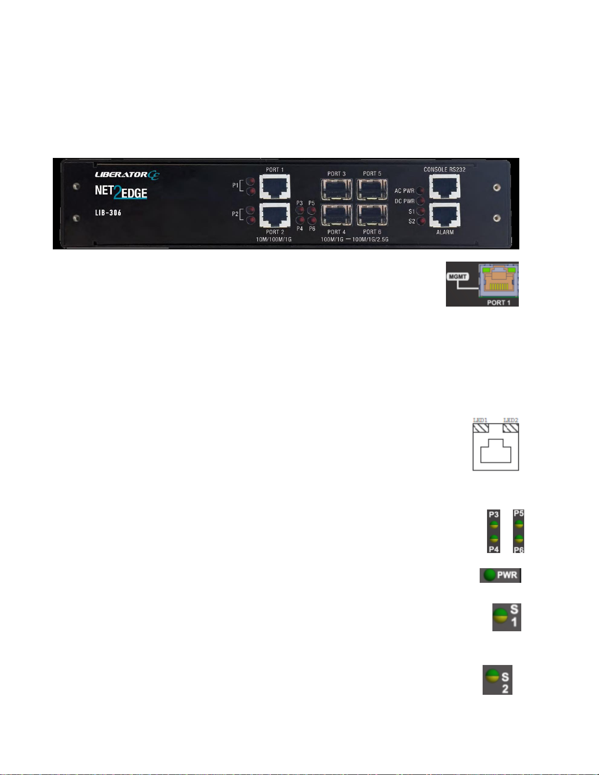
Front Panel
The LIB-306 front panels are shown and described below.
MGMT / PORT 1: Port1 (MGMT) is a normal data port, but by default it will be in a
separate private VLAN (PVLAN 1) that you can remove. You can enable or disable out-
of-band management on PORT 1. PORT 1 can be optionally configured to support
either out-of-band management or it can be used as a normal data UNI/NNI port.
See Connecting Via the MGMT Port / Web GUI on page 15. By default, PORT 1 is enabled as a
Management port with a default IP and subnet mask. See Factory Defaults on page 16. Full instructions for
disabling the management function and how to use the port as a normal data port are provided in the CLI
Reference and Web User Guide manuals.See also Switching MGMT / PORT 1 Modes on page 18.
GigabitEthernet 1/1 (Port 1) is configured by default to act as a management port. This is achieved by
placing Port 1 in Private VLAN 6 which isolated traffic at layer 2 on this port from other front ports which are
by default placed into Private VLAN 1.
PORT 2 - PORT 4 (or PORT 1 & 2): Ethernet RJ-45 (10M/100M/1 Gbps) twisted pair ports (IEEE
10/100/1000Base-T interfaces). The Port 1 and Port 2 (or PORT 1-4) LEDs are shown and
described below:
LED1: Link/Activity/Duplex: ON = Link, OFF= No link
BLINK = Activity
Green = Full duplex, Yellow = Half duplex
LED2: Speed: Green = 1000Mbs, Yellow = 100Mbs, OFF = 10Mbs
PORT 5 & 6 (or PORT 3 - PORT 6 on the LIB-306-42): Two (or four) SGMII interfaces. The Serial Gigabit
Media-independent Interface (SGMII) interfaces can operate at multiple speeds of 100M/1G/2.5G bps.
P3 - P6 LED (P5 - P6 on the LIB-306-42): fiber link status. When lit in green,indicates a 1G fiber
link / activity. When lit in amber, indicates a 100M fiber link / activity. When off indicates no fiber
link established.
PWR LED: Green Power LED: On = power applied to the PC board. Flashes Green during LIB-306 boot up.
S1 LED: System Status LED (Bi-color Green and Amber):
During boot up –Amber
Normal operation –Green
Firmware upgrade –Flashes Green
Fatal condition logged –Flashes Amber
S2 LED: S2 is used for alarms. You can set the alarm severity to Info, Warning, or Error.
The severity is included in the alarm message and also sets the S2 LED color when the alarm is
triggered. The S2 LED is amber for an Info alarm, red for a Warning alarm, and blinking red for
an Error alarm. If not set, the default alarm severity is Info. See the back panel ALARMS port

Net2Edge LIB-306 Install Guide
Install Guide Rev. D www.net2edge.com Page 11 of 25
description on page 13.
S2 LED is green when at least one alarm source is being monitored (enabled) if the severity level is Info.
S2 LED is amber when at least one event source has triggered if the severity level is Warning.
S2 LED is flashing amber when at least one event source has triggered if the severity level is Error.
S2 LED is off when all event sources are disabled if the severity level is Error.
CONSOLE:RJ-45 serial port 115200 baud CLI port. The LIB-306 RJ-45 console port allows root access to
its CLI (Command Line Interface) via a computer, regardless of the state of the switch (unless it is
completely dead). By connecting to the console port, out-of-band remote access to the CLI of the switch is
possible. This creates a secondary path to the switch outside the bandwidth of the network, which needs to
be secured without relying on the primary network.
ALARMS:Alarm inputs and outputs are RJ-45 connector with 2-IN and 2-OUT; 10-30VDC, 40mA
maximum; optically isolated from main board. You can connect up to two alarm inputs from external devices
in your environment (e.g., a fire alarm, a door, a temperature gauge) to the alarm input port on the switch
front panel. The figure below shows the location of the alarm pinouts. For each alarm input, you can
configure an open or closed circuit to trigger an alarm and configure the severity of the alarm. A triggered
alarm generates a system message. If you enter a descriptive name for the alarm, that name is included in
the system message. A triggered alarm also turns on the LED display. The LED is normally off, meaning no
alarm condition exists.
You can set the alarm severity to Info, Warning, or Error. The severity is included in the alarm message and
also sets the S2 LED color when the alarm is triggered. The S2 LED is amber for an Info alarm, red for a
Warning alarm, and blinking red for an Error alarm. If not set, the default alarm severity is Info.
You can use the LIB-306 web GUI or CLI to configure alarm contacts; see the related manual for details.
The ALARMS port pinning and basic block diagram are shown below.
The Alarm Input and Output truth tables are provided below.
Alarm Outputs
Alarm State & LED
behavior
Trigger
setting
Alarm relay out state
Asserted & Active
Close
relay closed
De-asserted & Not active
Close
relay open
Asserted & Active
Open
Relay open
De-asserted & Not active
Open
Relay closed

Net2Edge LIB-306 Install Guide
Install Guide Rev. D www.net2edge.com Page 12 of 25
Alarm Inputs
Wire state
Trigger
setting
Alarm state & LED
behavior
Energized
Close
Asserted & Active
De-energized
Close
De-asserted & Not active
Energized
Open
De-asserted & Not active
De-energized
Open
Asserted & Active
Connecting Power
You can connect LIB-306 power can be powered either via a DC or AC Source –or both.
Note that when power is initially applied (or when power is recycled) the LIB-306 front panel LEDs all light
for approximately 10 seconds. Some LEDs will remain lit, depending on the LIB-306 operating status and
port connections.
Notes:
The range of suitable wire for the DC power terminal screws is 12 to 26 AWG.
The DC power source must be safety certified.
Connecting Power Wires to the DC power connectors
1. Strip the wires to the proper length.
2. Insert the positive and negative power wires into the two outer screws on the DC power supply input
(the DC power supply is polarity insensitive, so there is no designated V+ or V– screw connector).
Make sure the wires are secure.
3. Insert the power wires from the LIB-306 into V+ and V- contacts in the power source—make sure the
wires are secure.
4. Turn the power source ON and observe that the green front panel PWR (power) LED is lit, indicating
that power is applied to the LIB-306.

Net2Edge LIB-306 Install Guide
Install Guide Rev. D www.net2edge.com Page 13 of 25
Installing SFP Modules and Fiber Cables
Warning
Visible and invisible laser radiation when open: DO NOT stare into the beam or view the beam directly with
optical instruments. Failure to observe this warning could result in an eye injury or blindness.
Use of controls, adjustments or the performance of procedures other than those specified herein may result
in hazardous radiation exposure.
Avoid bending fiber-optic cable beyond its minimum bend radius—any arc smaller than a few inches in
diameter can damage the cable and cause problems that are difficult to diagnose.
Installing SFPs
1. Attach an ESD-preventive wrist strap to your wrist and to a bare-metal grounded surface.
2. Have a replacement SFP or a transceiver-cage plug ready, as well as an antistatic mat and a rubber
safety cap for the SFP.
3. Locate the proper fiber cable.
4. Position the cable at the SFP as shown below.
Caution: Disconnect all cables before removing or installing an SFP module to prevent damage to the fiber
cable.
5. Insert the fiber cable ends completely into the SFP as shown below.
6. Insert the SFP fully into the cage as shown below.
Removing SFPs
7. Attach an ESD-preventive wrist strap to your wrist and to a bare-metal grounded surface.
8. Have a replacement SFP or a transceiver-cage plug ready, as well as an antistatic mat and a rubber
safety cap for the SFP.
9. Disconnect the LC cable for the SFP.
10. Pull the bale clasp handle out from the SFP to unlock the SFP.
11. Grasp the SFP bale clasp and pull the SFP approximately 0.5 inches (1.3 cm) out of the cage.
12. Using your fingers, grasp the body of the SFP and pull it completely from the cage.
13. Insert the rubber protector into the SFP module to protect it.
14. Place the SFP module in an antistatic bag or other protective environment.
LC Fiber
Cable
SFP
Switch
Fully Inserted SFP
Switch

Net2Edge LIB-306 Install Guide
Install Guide Rev. D www.net2edge.com Page 14 of 25
Installing Copper Cables
Copper Cable Configuration
Depending on the equipment type, data terminal equipment (DTE) or data communication equipment
(DCE), use a crossover or straight-through cable. See figure below.
Connecting Ethernet Cables
1. Locate or build an IEEE 802.3 compliant cable with male RJ-45 connectors installed at both ends as
shown below.
Pin
Out Jack Pin Assignments
1
Outgoing Data 1 (+)
2
Outgoing Data 2 (-)
3
Incoming Data 1 (+)
4
Not Connected
5
Not Connected
6
Incoming Data 2 (-)
7
Not Connected
8
Not Connected
2. Connect the RJ-45 connector at one end of the cable to the LIB-306 RJ-45 port.
3. Connect the RJ-45 connector at the other end of the cable to the RJ-45 Ethernet network port.
1
2
3
6
Straight-Through Cable Crossover Cable
1
2
3
6
1
2
3
6
1
2
3
6
Twisted Pair #1
Twisted Pair #2
Twisted Pair #1
Twisted Pair #2

Net2Edge LIB-306 Install Guide
Install Guide Rev. D www.net2edge.com Page 15 of 25
Connecting Via the Serial CONSOLE / CLI
The LIB-306 CLI interface is an Industry standard CLI and consists of different configuration commands
structure with ability to configure and view the configuration using the Serial Console, Telnet, or SSH.
Connecting Via the MGMT Port / Web GUI
The LIB-306 supports these Web browsers:
Internet Explorer
Firefox
Google Chrome
See the LIB-306 Web User Guide or the LIB-306 CLI Reference manual for details on configuration and
management methods.
To login using the serial interface (e.g., HyperTerminal) use the setup 115200, 8, none, 1, none.
See the LIB-306 CLI Reference manual for details.
Type help, ?, or press the Enter key to display the commands as shown below.

Net2Edge LIB-306 Install Guide
Install Guide Rev. D www.net2edge.com Page 16 of 25
Factory Defaults
The LIB-306 comes with the following defaults:
DHCP
Ipv4 Address
Ipv6 Address
Enabled
192.168.0.1
::192.0.2.1
Note: after power up, the LIB-306 has DHCP enabled. If a DHCP server is available, the LIB-306 will obtain
an IP address from the DHCP server. If no DHCP server is available, after 70 seconds, the LIB-306 will fall
back to the default IP address of 192.168.0.1/24.
Static IP configuration
You can change the defaults via the CLI. Note: you may want to save the existing config to startup config
first by using the copy running-config command. See the CLI Reference manual for details. To manually
configure the IP address:
1. At the command prompt type # configure terminal and press the Enter key to enter config mode.
2. Enter the command (config)# interface vlan 1 and press the Enter key to enter the interface config
mode.
3. Set the IP to 192.168.1.110 and subnet to 255.255.255.0 (substitute what you would like the static IP
and subnet to be). You can change the current IP address using the following command:
(config-if-vlan)# ip address 192.168.1.110 255.255.255.0
See the LIB-306 CLI Reference manual for CLI command information for CLI details.
4. To verify the change, you can log in to the LIB-306 Web GUI using IP address 192.168.1.110. See the
LIB-306 Web User Guide for more information.
Login using PuTTY Terminal Emulator Software
1. Start a PuTTY session. In the PuTTY dialog box in the “Host Name {or IP Address}” field, enter the IP
address of the switch (e.g., 192.168.1.110). In the Port field, enter 22.
2. Name the session in the “Saved Sessions” field (e.g., as LIB-306 SW).
3. Click the Save button and the dialog box displays.
4. Click the Open button to launch the login screen.
Note: If a Security Alert displays, click YES, if you trust the host and the key will be added to the
PuTTY cache. Click NO if you do not want to register the key for this session.
5. At the login prompt, type “admin” (default/lowercase).
6. Press the Enter key twice to bring up the Root (top) level commands as shown below.
See the LIB-306 CLI Reference manual for CLI command information for CLI details.

Net2Edge LIB-306 Install Guide
Install Guide Rev. D www.net2edge.com Page 17 of 25
Login Using Telnet
1. Use the Windows Start > Command Prompt menu path to display the command.
2. At the command prompt type Telnet and then 192.168.1.110 and press the Enter key
3. At the Username prompt, enter admin (lower case) and press the Enter key.
4. At the Password prompt press the Enter key to display the # prompt.
5. At the # prompt enter CLI commands as desired.
See the LIB-306 CLI Reference manual for CLI command information for CLI details.
Login Using the Web Interface
1. Launch a web browser (Internet Explorer/FireFox).
2. Enter the LIB-306 IP address (e.g., 192.168.0.1) in the browser URL field.
3. Press the Enter key to launch the login dialog box.
4. In the user name field type “admin” (lowercase) and leave the password field empty (no password).
5. Press the Enter key to launch the LIB-306 web GUI.
6. See the LIB-306 Web User Guide manual for web GUI configuration, monitoring, diagnostics, and
maintainance.
Re-Access the Web GUI via CLI Commands
You can use the following CLI commands to regain web GUI access (e.g., after a Software Upload).
# show ip int brief
Vlan Address Method Status
---- -------------------- -------- ------
# conf term
(config)# int vlan 1
(config-if-vlan)# ip addr 192.168.1.110 255.255.255.0
(config-if-vlan)# end
# show ip int brief
Vlan Address Method Status
---- -------------------- -------- ------
1 192.168.1.110/24 Manual UP
#
You can then access the web GUI via the IP address and netmask entered (e.g., 192.168.1.110 and
255.255.255.0 in the example above). See the LIB-306 CLI Reference manual for details.

Net2Edge LIB-306 Install Guide
Install Guide Rev. D www.net2edge.com Page 18 of 25
Switching MGMT / PORT 1 Modes
The LIB-306 MGMT / PORT 1 is a normal data port, but by default it will be in a separate private VLAN that
you can remove. You can enable or disable out-of-band management on Port 1. Port 1 can be optionally
configured to support either out-of-band management or it can be used as a normal data UNI/NNI port.
By default, Port 1 is enabled as a management port with a default IP (192.168.0.1/24) and subnet mask.
By default, all ports are VLAN unaware and members of VLAN 1 and Private VLAN 1.
To configure Port 1 as a normal front panel data port, use the settings below.
Normal front port:
interface GigabitEthernet 1/1
!
Management Port:
interface GigabitEthernet 1/1
no pvlan 1
pvlan 6
no ip dhcp forwarding
no spanning-tree
!
Configure the Default Management Port as a Data Port
The GigabitEthernet 1/1 (MGMT / PORT 1) is configured as a Management Port by default:
Alternatively, any port can be designated as a Management port. To change GigabitEthernet 1/1 to act as a
data port:
1. Disable spanning-tree on the port designated for Management. Remove pvlan 1 from the new interface
and disable dhcp forwarding, and add pvlan6:
(config)# int Gi 1/2
(config-if)# no spanning-tree
(config-if)# no pvlan 1
(config-if)# no ip dhcp forwarding
(config-if)# pvlan 6
2. Physically connect to the newly designated Management port.
3. Enable pvlan 1 for the new port designated as a data port.
4. If necessary enable spanning-tree on the new data port.
Additional instructions for disabling management are provided in CLI and Web manuals.

Net2Edge LIB-306 Install Guide
Install Guide Rev. D www.net2edge.com Page 19 of 25
Product Registration
It is important to register the product for the following reasons:
Software/Firmware/Driver updates.
Have access to all of our training tools, videos, content and downloads.
Technical documentation and information about support assistance.
Receive email alerts of new products according to personal interest.
3. Troubleshooting
This section provides basic LIB-306 troubleshooting procedures.
1. Verify the Product Description, Models, Applications, Features, and Specifications in the “Introduction”
section starting on page 4 of this manual.
2. Verify the procedures in section 2. Installation starting on page 8 of this manual.
3. Make sure your particular model supports the function attempted.
4. Verify the Installation. Check the Operating System, Web Browser, Telnet Client, and/or Terminal
Emulation package support.
5. Respond to any LIB-306 error messages (see the Error Messages section of the LIB-306 CLI
Reference or the LIB-306 Web User Guide.
6. Run the LIB-306 Diagnostics tests and verification functions (e.g., Ping, VeriPHY). See the
“Diagnostics” section of the LIB-306 Web User Guide manual.
7. Check the LIB-306 operating parameters (e.g., Information, CPU Load, Log, Detailed Log). See the
“Operation” section of the LIB-306 Web User Guide manual.
8. If you can access the LIB-306 via PuTTY or HyperTerminal but not via the web interface, in config
mode, enter the default keep_ip CLI command and try accessing the LIB-306 web interface again.
9. If you have problems displaying the LIB-306 web interface in IE, try displaying in Compatibility View
from the IE Tools > Compatibility View menu path.
10. Record the error condition. See “Recording Model and System Information” below.
11. Contact Net2Edge Tech Support. See section“4. Service, Warranty and Tech Support” on page 22.

Net2Edge LIB-306 Install Guide
Install Guide Rev. D www.net2edge.com Page 20 of 25
Recording Model and System Information
After performing the troubleshooting procedures, and before calling or emailing Technical Support, please
record as much information as possible in order to help the Net2Edge Tech Support Specialist.
1. Select the LIB-306 Configuration > System > Information menu path. (From the CLI, use the show
commands needed to gather the information below or as requested by the Net2Edge Support
Specialist).
2. Record LIB-306 Model Information:
Serial #: ___________________________ MAC Address: __________________________
System Uptime: _____________________ Software Version: ________________________
3. Record the Monitor menu information:
Monitor > System > Information: _____________________________________________________
Monitor > System > IP Status: ________________________________________________________
LED Status: ______________________________________________________________________
4. Provide additional Model and System information to your Technical Support Specialist. See the
“Troubleshooting” section above.
Your Net2Edge service contract number: _____________________________________
A description of the failure: _________________________________________________________
________________________________________________________________________________
________________________________________________________________________________
A description of any action(s) already taken to resolve the problem (e.g., changing mode, rebooting,
etc.): ____________________________________________________________________________
_________________________________________________________________________________
________________________________________________________________________________
The serial and revision numbers of all involved Net2Edge products in the network:
_________________________________________________________________________________
_________________________________________________________________________________
A description of your network environment (layout, cable type, etc.): _________________________
_________________________________________________________________________________
________________________________________________________________________________
Network load and frame size at the time of trouble (if known): ______________________________
Table of contents
Other Net2Edge Media Converter manuals

Popular Media Converter manuals by other brands


Mondial Designs Limited
Mondial Designs Limited Aragon D2A2 user guide

Anschutz
Anschutz 101-533.NG001 Operator's and service manual

Snell Advanced Media
Snell Advanced Media IQUDC30 User instruction manual
Runco
Runco ViViX PIXEL FOR PIXEL PFP-7 Owner's operating manual

Comnet
Comnet CNGEMC4+2/M Installation and operation manual

Lenze
Lenze TML operating instructions


