NETASQ NA-F25 User manual

INSTALLATION GUIDE
Copyright NETASQ 2010 Page 1/65
P
PR
RE
ES
SE
EN
NT
TA
AT
TI
IO
ON
N
A
AN
ND
D
I
IN
NS
ST
TA
AL
LL
LA
AT
TI
IO
ON
N
O
OF
F
N
NE
ET
TA
AS
SQ
Q
P
PR
RO
OD
DU
UC
CT
TS
S
Date Version Author Details
April 2010 V1.0 NETASQ Creation
September 2010 V1.1 NETASQ Update
Reference: naengde_product-installation

INSTALLATION GUIDE
Copyright NETASQ 2010 Page 2/65
You are strongly advised to read this document in full before installing any NETASQ UTM product.
This guide aims to facilitate the quick integration of a NETASQ firewall into your network, but does not
provide information on how to configure it. Please consult the relevant help file on the CD-ROM provided for
configuration matters.

INSTALLATION GUIDE
Copyright NETASQ 2010 Page 3/65
Copyright © NETASQ 2010. All rights reserved.
Any reproduction, adaptation or translation of this current document without prior written permission is
prohibited, except where expressly allowed by copyright laws.
NETASQ applies a method of constant development and as such reserves the right to modify and improve
any product described in the document without prior notice.
Under no circumstances shall NETASQ be held liable for any loss of data or revenue, or any special damage
or incident, resulting from or indirectly caused by the use of the product and its associated documentation.
The contents of this document relate to the developments in NETASQ’s technology at the time of its writing.
With the exception of the mandatory applicable laws, no guarantee shall be made in any form whatsoever,
expressly or implied, including but not limited to implied warranties as to the merchantability or fitness for a
particular purpose, as to the accuracy, reliability or the contents of the document. NETASQ reserves the
right to revise this document, to remove sections or to remove this whole document at any moment without
prior notice.
To ensure the availability of products, which may vary according to your geographical locations, contact your
nearest NETASQ distributor.
Products concerned
U30, U70, U120, U250, U450, U1100, U1500 and U6000,
NG1000-A, NG5000-A.

Copyright NETASQ 2010 Page 4/65
INSTALLATION GUIDE: CONTENTS
C
CO
ON
NT
TE
EN
NT
TS
S
CONTENTS 4
1INTRODUCTION 7
2USAGE PRECAUTIONS 8
3UPON RECEIVING YOUR FIREWALL 10
3.1INTEGRITY OF THE PRODUCT 10
3.1.1LABELS 10
3.1.2QUALITY SEAL 11
3.1.3FIREWALL SEAL 12
3.2CONTENTS OF THE PACKAGING 12
3.2.1THE CHASSIS 13
3.3WARRANTY AND DISMANTLING THE APPLIANCE 13
4PRESENTATION OF THE APPLIANCES 14
4.1FRONT PANELS OF PRODUCTS IN THE URANGE 14
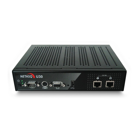
4.2THE U30 APPLIANCE 14
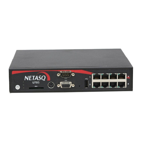
4.3THE U70 APPLIANCE 16
4.4THE U120 APPLIANCE 17
4.5THE U250 APPLIANCE 18
4.6THE U450 APPLIANCE 20
4.7THE U1100 APPLIANCE 21
4.7.1FRONT PANEL 21
4.7.2REAR PANEL 22
4.8THE U1500 APPLIANCE 22
4.8.1FRONT PANEL 23
4.8.2REAR PANEL 24
4.9THE U6000 APPLIANCE 25
4.9.1FRONT PANEL 25
4.9.2REAR PANEL 26
4.10THE NG1000-A APPLIANCE 27
4.10.1FRONT PANEL 27
4.10.2REAR PANEL 28
4.11THE NG5000-A APPLIANCE 28
4.11.1FRONT PANEL 28
4.11.2REAR PANEL 30
5CONNECTIONS 31
5.1INSTALLATION PRECAUTIONS 31
5.1.1LOCATION 31
5.2POWER PLUG 31
5.3CONNECTION FOR ADMINISTERING THE APPLIANCE 32
5.4CONNECTING TO THE NETWORK 32
5.4.1U30 32
5.4.2U70 33

Copyright NETASQ 2010 Page 5/65
INSTALLATION GUIDE: CONTENTS
5.4.3U120 33
5.4.4U250 33
5.4.5U450 34
5.4.6U1100 34
5.4.7U1500 34
5.4.8U6000 35
5.4.9NG1000-A 35
5.4.10NG5000-A 36
5.4.11USING A STRAIGHT CABLE 36
5.4.12USING A CROSSOVER CABLE (CABLE PROVIDED WITH THE PRODUCT) 36
5.4.13ANTISPOOFING MECHANISM 37
6PHYSICAL INSTALLATION OF THE APPLIANCE 37
6.1PREPARATION BEFORE INSTALLATION 37
6.1.1PREPARATION OF THE NETWORK CABLES 37
6.1.2PREPARATION OF THE RACKING CABINET OR BAY 38
6.1.3PREPARATION OF INTERNET ACCESS 38
6.2PLACING THE APPLIANCE IN A BAY 38
6.2.1INSTALLING A U30 OR U70 38
6.2.2INSTALLING A U120, U250 OR U450 39
6.2.3INSTALLING A U1100, U1500 OR U6000 40
6.2.4PRECONFIGURING A FIREWALL 41
7INITIAL CONNECTION TO THE PRODUCT 42
7.1PREREQUISITES 42
7.1.1MINIMUM CONFIGURATION FOR CONFIGURING A NETASQ FIREWALL 42
7.1.2PREPARATION OF INTERNET ACCESS 42
7.2CONFIGURATION 43
7.3REGISTERING AND INSTALLING THE PRODUCT 44
APPENDIX A: UPDATING THE LICENSE 45
INSTALLING THE LICENSE 48
APPENDIX B: RESETTING THE FIREWALL 49
APPENDIX C: ADDING AN ADDITIONAL U6000 NETWORK CARD 51
GENERAL POINTS 51
AUTHORIZATION 51
WARNING 51
APPLIANCES CONCERNED 52
DESCRIPTION OF THE CARDS 52
STEPS TO FOLLOW 52
INTRODUCTION 52
PROCEDURE FOR ADDING A CARD 53
7.3.1ADDING A PCI-E NETWORK CARD 54
7.3.2ADDING A 2ND PCI-E NETWORK CARD 56
7.3.3ADDING A PCI-X NETWORK CARD 56
7.4SCENARIOS FOR ADDING PCI-X CARDS 58
7.4.1SCENARIO IN WHICH A 6-PORT PCI-X CARD IS ADDED TO A DEFAULT CONFIGURATION 59
7.4.2SCENARIO IN WHICH A 2-PORT PCI-X CARD IS ADDED TO A DEFAULT CONFIGURATION 60
7.4.3SCENARIO IN WHICH A 6-PORT PCI-X CARD IS ADDED AFTER A PCI-E CARD 61
APPENDIX D: ADDING AN NG1000-A AND NG5000-A EXTENSION MODULE 62

Copyright NETASQ 2010 Page 6/65
INSTALLATION GUIDE: CONTENTS
GENERAL POINTS 62
APPLIANCES CONCERNED 62
DESCRIPTION OF THE CARDS 62
PROCEDURE FOR ADDING A CARD 62
APPENDIX E: INSTALLING VIA THE CD-ROM 64
GLOSSARY 65

Copyright NETASQ 2010 Page 7/65
INSTALLATION GUIDE : 1. INTRODUCTION
1
1
I
IN
NT
TR
RO
OD
DU
UC
CT
TI
IO
ON
N
Thank you for choosing NETASQ. Designed to protect structures of all sizes, NETASQ’s UTM appliances
are pre-configured: no hardware or software installation is needed and no UNIX knowledge is necessary, just
a user-friendly configuration via a graphical interface. There are currently 10 products in the range: U30,
U70, U120, U250, U450, U1100, U1500, U6000, NG1000-A and NG5000-A.
The NETASQ UTM appliance allows the definition of incoming or outgoing access control rules. Its concept
is simple: any incoming or outgoing transmission passing through the NETASQ Firewall is monitored,
authorized or denied according to the rules, packet by packet.
The NETASQ Firewall is based on an upgraded packet filtering mechanism which brings a high level of
security. All NETASQ Firewalls integrate the ASQ (Active Security Qualification) technology developed by
NETASQ. This technology allows detection and blocking of hacking attempts in real time – illegal packets,
denial of service attempts, anomalies in a connection, port scans, buffer overflows, etc.
In the case of an intrusion attempt, depending on the instructions given in the security policy, the NETASQ
Firewall blocks the transmission, generates an alarm and stores the information linked to the packet which
had set off the alarm. As such, you would be able to analyze the attack and trace its source.
The Firewall not only allows preventing, or restricting to just certain services, incoming connections on your
network, but also allows monitoring the use of the internet by your internal users (HTTP, FTP, SMTP...). You
may also monitor your users by authenticating them via an internal or external authentication database.
The NETASQ Firewall also manages port and address translation mechanisms. These mechanisms provide
security (by masking your internal address range) and flexibility (by enabling the use of any private internal
addressing range) and reduce costs (by enabling the provision of several servers on the internet with a
single public IP address).
With ASQ, NETASQ’s IPS (Intrusion Prevention System) engine, a NETASQ firewall offers all the more
security. Its plugin architecture allows monitoring most of the traffic circulating through the Firewall even at
the application layer. Its performance in terms of throughput, number of rules and number of tunnels, has
been increased tenfold.
Thanks to its Windows-based user interface, it allows the rapid and simple definition of your network's
security rules, from a local workstation running under Windows. You may also monitor your Firewall’s
activity in real time.
The NETASQ Firewall is also equipped with advanced log functions. In an intrusion attempt, the network
administrator may access all data sent before the attack and see how it had been prepared. NETASQ
EVENT REPORTER provides you with a graphical view and fine analysis of logs generated on the Firewall.
Lastly, the NETASQ Firewall includes VPN gateway functions allowing you to establish encrypted tunnels
with other VPN equipment. In this way, your communications between sites or with your mobile users
(“Road Warriors”) may be secured even while using an insecure communication infrastructure like the
internet.
This installation guide presents the products (front and rear panels), explains the physical installation
process and lastly allows you to configure your product in order to integrate it into the desired network
architecture. It also explains how to insert additional network cards to the U6000 product or to insert
extension modules to the NG1000-A and NG5000-A products.

Copyright NETASQ 2010
Page 8/65
INSTALLATION GUIDE : 2. USAGE PRECAUTIONS
2
2
U
US
SA
AG
GE
E
P
PR
RE
EC
CA
AU
UT
TI
IO
ON
NS
S
WARNING
Using the wrong type of lithium batteries may cause the components to explode. Please follow the
indications given by the manufacturer of the lithium batteries (these are used in your firewall) on how
to recycle used batteries.
WARNING
Ensure that you place heavier equipment in the lower racks of the cabinet, and the lighter appliances
in the higher racks.
WARNING
Most NETASQ appliances require a land-based connection. Ensure that your power grid has good
ground conductivity, which meets NETASQ’s specifications concerning the power supply of firewalls.
It would be even better to protect the power supply with UPS devices.
WARNING
NETASQ appliances do not have power supply switches. In all cases, unplugging the power cable
from the mains socket will disconnect the appliance from the main power supply.
WARNING
NETASQ firewalls should not be installed in locations where the temperature may exceed 35°C. The
table below indicates the operating temperature, storage temperature and humidity level for each
appliance.
Operating temperature Storage temperature Humidity
U30 5° to 40°C (51° to 104°F) -30° to 65°C (-22° to
149°F) 20% to 90% (sans
condensation)
U70 5° to 40°C (51° to 104°F) -30° to 65°C (-22° to
149°F) 20% to 90% (without
condensation)
U120 5° to 40°C (51° to 104°F) -30° to 65°C (-22° to
149°F) 20% to 90% (without
condensation)
U250 5° to 40°C (55° to 104°F) -30° to 65°C (-22° to
149°F) 20% to 90% (without
condensation)
U450 5° to 40°C (55° to 104°F) -30° to 65°C (-22° to
149°F) 20% to 90% (without
condensation)
U1100 10° to 35°C (50° to 95°F) -30° to 65°C (-22° to
149°F) 20% to 90% (without
condensation)
U1500 10° to 35°C (50° to 95°F) -30° to 65°C (-22° to
149°F) 20% to 90% (without
condensation)
U6000 10° to 35°C (50° to 95°F) -30° to 65°C (-22° to
149°F) 20% to 90% (without
condensation)
NG1000-A 10° to 35°C (50° to 95°F) -20° to 65°C (-4° to
149°F) 20% to 80% (without
condensation)
NG5000-A 10° to 35°C (50° to 95°F) -20° to 70°C (-4° to
158°F) 20% to 80% (without
condensation)

Copyright NETASQ 2010
Page 9/65
INSTALLATION GUIDE : 2. USAGE PRECAUTIONS
WARNING
Ensure that nothing obstructs the air vents on the product in order to guarantee maximum air
circulation.
WARNING
U30, U70, U6000, NG1000-A and NG5000-A appliances comply with the requirements in the
EN55022 standard, Class A. In residential environments, these products may cause radioelectric
disturbances, in which case the user may be obliged to take the appropriate measures.
WARNING
Ensure that you unplug ALL power cables connected to the firewall before beginning any
interventions on it.
WARNING
The metal brackets on the front panel of the U6000, NG1000-A and NG5000 products are not to be
used for lifting the product but only for racking the firewall or for removing it from its racks.

Copyright NETASQ 2010 Page 10/65
INSTALLATION GUIDE : 3. UPON RECEIVING YOUR FIREWALL
3
3
U
UP
PO
ON
N
R
RE
EC
CE
EI
IV
VI
IN
NG
G
Y
YO
OU
UR
R
F
FI
IR
RE
EW
WA
AL
LL
L
3
3.
.1
1
I
In
nt
te
eg
gr
ri
it
ty
y
o
of
f
t
th
he
e
p
pr
ro
od
du
uc
ct
t
In order to guarantee the integrity of your product, NETASQ has set up several mechanisms. Check these
mechanisms to confirm that your product has not been tampered with:
3.1.1 Labels
Every firewall is delivered in a cardboard box with three labels affixed, indicating information identifying the
product it contains and its version. There is also a “Serial number” label affixed directly on the product. The
3rd label serves to identify the configuration of the product. Check that this information matches your order.
IMPORTANT
It is best that you have your serial number and web password (given on the label on the underside of
the product) at hand before connecting or installing the firewall.
The 3 labels are as follows:
Serial number label: this label, pasted on the product, indicates information such as the serial number,
sales platform, web activation code (which enables the activation of the client account in the NETASQ
website’s client area) and the barcode that contains the product’s serial number.
Figure 1: Serial number label
Packaging identification label: this label, pasted on the packaging of the product, provides information
relating to the sales platform, serial number of the product and the barcode containing the product’s serial
number.

Copyright NETASQ 2010 Page 11/65
INSTALLATION GUIDE : 3. UPON RECEIVING YOUR FIREWALL
Figure 2: Packaging identification label
Version number label: this label, pasted ion the packaging, indicates the software version installed
on the firewall. The version is defined by a version number and model (which correspond to a certain
export zone). This label helps to check later if the delivered version has been certified.
Figure 3: Product version label
3.1.2 Quality seal
Every firewall is delivered in a cardboard box on which a NETASQ-specific quality seal or a “NETASQ
QUALITY SEAL” is affixed. Check that there is such a seal on your product’s packaging.
Below is the type of label or quality seal that you should expect to find:
Figure 4: "Quality seal" label

Copyright NETASQ 2010
Page 12/65
INSTALLATION GUIDE : 3. UPON RECEIVING YOUR FIREWALL
Figure 5: Warranty band
If this band is missing, contact your distributor soonest possible to find out why the packaging has been
opened.
Confirm that these security mechanisms are in place in order to ensure the integrity of the product delivered
as well as any subsequent dispute concerning the application of the guarantee in the event a breach has
been observed more than 48 hours after receipt of the product. Feel free to contact your distributor if any of
the elements does not comply with its description.
3.1.3 Firewall seal
A seal label is pasted on all firewalls. This prevents the replacement or modification of the firewall’s hardware
elements. This label has the peculiarity of displaying a message (VOID) that cannot be erased once the
label has been removed. There are two types of seal: one pasted by NETASQ after production and one
pasted by your partner if a maintenance operation has been performed on your appliance (your partner
would have explained this maintenance operation to you through an activity certificate).
Figure 6: Firewall seal
Confirm that these security mechanisms are in place in order to ensure the integrity of the product delivered
as well as any subsequent dispute concerning the application of the guarantee in the event a breach has
been observed more than 48 hours after receipt of the product. Feel free to contact your distributor if any of
the elements does not comply with its description.
3
3.
.2
2
C
Co
on
nt
te
en
nt
ts
s
o
of
f
t
th
he
e
p
pa
ac
ck
ka
ag
gi
in
ng
g
Keep the cardboard packaging safely in case you need it later for transporting the firewall. It has been
designed to give your NETASQ firewall optimum protection (shock and temperature resistance).
Upon delivery, check that the following have been included in the packaging
The NETASQ firewall in the model ordered
A power cable (2 cables for U6000, NG1000-A and NG5000-A appliances) (ref. 1076036). For U30
and U70 products, the cable would be a power cable specific to the power supply unit (plug attached
to the unit).
A crossover DB9F serial cable (ref. 1076033) (optional)
An RJ 45 crossover cable (blue cable, ref. 1076034)
The NETASQ software suite CD-ROM (Administration Suite)
A sheet indicating the license agreement.
Brackets and fastening system for racking your firewall (except for U30 and U70)
The power pack for U30 and U70.

Copyright NETASQ 2010
Page 13/65
INSTALLATION GUIDE : 3. UPON RECEIVING YOUR FIREWALL
Rubber feet for IU products (U120, U250 et U450)
If any of the elements is missing, contact your distributor immediately.
NOTE
For an after-sales exchange, the package will only contain the product and the external power supply
unit (U30, U70).
3.2.1 The chassis
Flexible feet have been placed under the chassis of the firewall to ensure that the NETASQ firewall is on a
stable plane (on a desk or on other IT equipment) and is protected from scratches.
These feet are delivered separately for 1U models (products that can be installed on a desk or in a rack), ie,
U120, U250, U450, U1100 and U1500.
These feet can be delivered already installed on the appliance for non-rackable products (U30 and U70).
U6000, NG1000-A and NG5000-A appliances are delivered with racking rails (sliding rails) in addition to front
attachment brackets. These rails have to be set up on prder to prevent deterioration of the product.
3
3.
.3
3
W
Wa
ar
rr
ra
an
nt
ty
y
a
an
nd
d
d
di
is
sm
ma
an
nt
tl
li
in
ng
g
t
th
he
e
a
ap
pp
pl
li
ia
an
nc
ce
e
WARNING
Under no circumstances should you take apart a NETASQ appliance on your own. Only NETASQ
and its approved maintenance agents are authorized to do so. Your warranty will be rendered null
and void should you dismantle a NETASQ firewall on your own.

INSTALLATION GUIDE : 4. PRESENTATION OF THE APPLIANCES
Copyright NETASQ 2010
Page 14/66
4
4
P
PR
RE
ES
SE
EN
NT
TA
AT
TI
IO
ON
N
O
OF
F
T
TH
HE
E
A
AP
PP
PL
LI
IA
AN
NC
CE
ES
S
4
4.
.1
1
F
Fr
ro
on
nt
t
p
pa
an
ne
el
ls
s
o
of
f
p
pr
ro
od
du
uc
ct
ts
s
i
in
n
t
th
he
e
U
U
r
ra
an
ng
ge
e
On the various models, the 3 LEDs (from bottom to top) described below will appear on the front panel:
NOTE
The U6000 appliance has other LEDs that will be covered later in this document.
For all models, upon startup, the LEDs light up in the following order:
Power Status Online
The Power LED will light up first, then Status, then Online. The Online LED, which indicates that the
product is running, will light up after about 2 minutes.
For all models, upon shutdown, the LEDs shut off in the following order:
Power Status Online
The Online LED goes off first, then Status followed by Power.
The connectors on U30, U70, U120, U250 and U450 appliances are located on the front panel.
4
4.
.2
2
T
Th
he
e
U
U3
30
0
a
ap
pp
pl
li
ia
an
nc
ce
e
The U30 appliance has the following characteristics:
3. Online LED (green)
2. Status LED (green)
1. Power LED (yellow)

INSTALLATION GUIDE : 4. PRESENTATION OF THE APPLIANCES
Copyright NETASQ 2010
Page 15/66
Throughput of 200 Mbits/s.
50,000 concurrent connections.
4,000 new sessions per second.
1. Software shutdown button.
2. LEDs from bottom to top: Power/Status/Online.
3. Serial port: for connecting the firewall directly to a PC or modem.
4. PS2 mini-din port: for connecting a keyboard.
5. VGA port: for connecting a monitor.
6. Button to reset to the default configuration (defaultconfig).
7. 1 USB port: for secure configuration or updates.
8. OUT Interface.
9. IN Interface.
Point 1: to shut down the software, hold down the software shutdown button for 4 seconds (until the Online
(green) LED goes off).
NOTE: There is no internal fan on this appliance.
Point 2: the Power LED (yellow) indicates that the product has been plugged in. If this is the only LED that
lights up, this means that the appliance is off.
The product is running when the Power LED and the Status and Online LEDs (green) are visible. The
Online LED will be the last to light up when the product is running. Traffic will pass through the interfaces.
When the appliance is starting, shutting down or being updated, only the Status and Power LEDs will light
up. WARNING
You are strongly advised against unplugging the product when the Status LED is starting, shutting
down or being updated.
The Status LED will blink (quick blinking every 250 milliseconds) in the event of a major failure of the product
(hardware modification, faulty network interface, etc). In this case, do contact your distributor.
Points 3, 4 and 5: these different ports enable access to the appliance in console mode.
The LEDs above the interfaces provide indications as to the throughput. For the U30, an interface with a
LED that does not light up indicates a throughput of 10 mbits/s, an interface with 2 LEDs that light up indicate
a throughput of 100 mbits/s.
1
2
3
4
5
6
7
8
9

INSTALLATION GUIDE : 4. PRESENTATION OF THE APPLIANCES
Copyright NETASQ 2010
Page 16/66
Blinking LEDs indicate the presence of network activity.
NOTE: power is supplied to this appliance from outside the rear panel. An upgrade to version
8.0 is recommended.
4
4.
.3
3
T
Th
he
e
U
U7
70
0
a
ap
pp
pl
li
ia
an
nc
ce
e
The U70 appliance has the following characteristics:
Throughput of 600 Mbits/s.
100,000 concurrent connections.
6 Gigabit interfaces.
6,000 new sessions per second.
1. Software shutdown button.
2. LEDs from bottom to top: Power/Status/Online.
3. Serial port: for connecting the firewall directly to a PC or modem.
4. PS2 mini-din port: for connecting a keyboard.
5. VGA port: for connecting a monitor.
6. Button to reset to the default configuration (defaultconfig).
7. 1 USB port: for secure configuration or updates.
8. OUT Interface.
9. IN Interface.
Point 1: to shut down the software, hold down the software shutdown button for 4 seconds (until the Online
(green) LED goes off).
NOTE: The fan is directly linked to the power supply.
Point 2: the Power LED (yellow) indicates that the product has been plugged in but has been shut down. If
this is the only LED that lights up, this means that the appliance is off.
The product is running when the Power LED and the Status and Online LEDs (green) are visible. The
Online LED will be the last to light up when the product is running. Traffic will pass through the interfaces.
When the appliance is starting, shutting down or being updated, only the Status and Power LEDs will light
up.
9
1
2
3
4
5
6
7
8

INSTALLATION GUIDE : 4. PRESENTATION OF THE APPLIANCES
Copyright NETASQ 2010
Page 17/66
WARNING
You are strongly advised against unplugging the product when the Status LED is restarting, shutting
down or being updated.
The Status LED will blink (quick blinking every 250 milliseconds) in the event of a major failure of the product
(hardware modification, faulty network interface, etc). In this case, do contact your distributor.
For an appliance configured in high availability, the Online LED will light up intermittently (for every second it
lights up, it will go off for 2 seconds). This means that the appliance is in passive mode.
Points 3, 4 and 5: these different ports enable access to the appliance in console mode.
The LEDs above the interfaces provide indications as to the throughput. For the U70, if the left LED lights up
on an IN interface, this indicates a throughput of 10 mbits/s, 2 LEDs that light up indicate a throughput of 100
mbits/s and if the right LED lights up, this indicates a throughput of 1000 mbits/s.
One or two blinking LEDs on an IN interface indicate the presence of network activity.
NOTE: power is supplied to this appliance from outside the rear panel. An upgrade to version
8.0 is recommended.
4
4.
.4
4
T
Th
he
e
U
U1
12
20
0
a
ap
pp
pl
li
ia
an
nc
ce
e
The U120 appliance has the following characteristics:
Throughput of 700 Mbits/s.
200,000 concurrent connections.
6 Gigabit interfaces.
6,500 new sessions per second.
1. Software shutdown button.
2. LEDs from bottom to top: Power/Status/Online.
3. Serial port: for connecting the firewall directly to a PC or modem.
4. PS2 mini-din port: for connecting a keyboard.
5. VGA port: for connecting a monitor.
6. Button to reset to the default configuration (defaultconfig).
7. 1 USB port: for secure configuration or updates.
1
8
2
3
4
5
6
7
9

INSTALLATION GUIDE : 4. PRESENTATION OF THE APPLIANCES
Copyright NETASQ 2010
Page 18/66
8. OUT Interface.
9. IN Interface.
Point 1: to shut down the software, hold down the software shutdown button for 4 seconds (until the Online
(green) LED goes off).
NOTE: The fan is directly linked to the power supply.
Point 2: the Power LED (yellow) indicates that the product has been plugged in but has been shut down. If
this is the only LED that lights up, this means that the appliance is off.
The product is running when the Power LED and the Status and Online LEDs (green) are visible. The
Online LED will be the last to light up when the product is running. Traffic will pass through the interfaces.
When the appliance is starting, shutting down or being updated, only the Status and Power LEDs will light
up.
WARNING
You are strongly advised against unplugging the product when the Status LED is starting, shutting
down or being updated.
The Status LED will blink (quick blinking every 250 milliseconds) in the event of a major failure of the product
(hardware modification, faulty network interface, etc). In this case, do contact your distributor.
For an appliance configured in high availability, the Online LED will light up intermittently (for every second it
lights up, it will go off for 2 seconds). This means that the appliance is in passive mode.
Points 3, 4 and 5: these different ports enable access to the appliance in console mode.
The LEDs above the interfaces provide indications as to the throughput. For the U120, if the left LED lights
up on an IN interface, this indicates a throughput of 10 mbits/s, 2 LEDs that light up indicate a throughput of
100 mbits/s and if the right LED lights up on an IN interface, this indicates a throughput of 1000 mbits/s.
One or two blinking LEDs on an IN interface indicate the presence of network activity.
NOTE: power is supplied to this appliance from inside the rear panel. An upgrade to version 8.0
is recommended.
4
4.
.5
5
T
Th
he
e
U
U2
25
50
0
a
ap
pp
pl
li
ia
an
nc
ce
e
The U250 appliance has the following characteristics:
Throughput of 850 Mbits/s.
400,000 concurrent connections.
6 Gigabit interfaces.
8,500 new sessions per second.

INSTALLATION GUIDE : 4. PRESENTATION OF THE APPLIANCES
Copyright NETASQ 2010
Page 19/66
1. Software shutdown button.
2. LEDs from bottom to top: Power/Status/Online.
3. Serial port: for connecting the firewall directly to a PC or modem.
4. PS2 mini-din port: for connecting a keyboard.
5. VGA port: for connecting a monitor.
6. Button to reset to the default configuration (defaultconfig).
7. 1 USB port: for secure configuration or updates.
8. OUT Interface.
9. IN Interface.
Point 1: to shut down the software, hold down the software shutdown button for 4 seconds (until the Online
(green) LED goes off).
NOTE: The fan is directly linked to the power supply.
Point 2: the Power LED (yellow) indicates that the product has been plugged in but has been shut down. If
this is the only LED that lights up, this means that the appliance is off.
The product is running when the Power LED and the Status and Online LEDs (green) are visible. The
Online LED will be the last to light up when the product is running. Traffic will pass through the interfaces.
When the appliance is starting, shutting down or being updated, only the Status and Power LEDs will light
up. WARNING
You are strongly advised against unplugging the product when the Status LED is starting, shutting
down or being updated.
The Status LED will blink (quick blinking every 250 milliseconds) in the event of a major failure of the product
(hardware modification, faulty network interface, etc). In this case, do contact your distributor.
For an appliance configured in high availability, the Online LED will light up intermittently (for every second it
lights up, it will go off for 2 seconds). This means that the appliance is in passive mode.
Points 3, 4 and 5: these different ports enable access to the appliance in console mode.
The LEDs above the interfaces provide indications as to the throughput. For the U250, if the left LED lights
up on an IN interface, this indicates a throughput of 10 mbits/s, 2 LEDs that light up indicate a throughput of
100 mbits/s and if the right LED lights up, this indicates a throughput of 1000 mbits/s.
One or two blinking LEDs on an IN interface indicate the presence of network activity.
1
3
5
8
2
4
6
7
9

INSTALLATION GUIDE : 4. PRESENTATION OF THE APPLIANCES
Copyright NETASQ 2010
Page 20/66
NOTE: power is supplied to this appliance from inside the rear panel. An upgrade to version 8.0
is recommended.
4
4.
.6
6
T
Th
he
e
U
U4
45
50
0
a
ap
pp
pl
li
ia
an
nc
ce
e
The U450 appliance has the following characteristics:
Throughput of 1000 Mbits/s.
600,000 concurrent connections.
15 Gigabit interfaces.
10,500 new sessions per second.
1. Software shutdown button.
2. LEDs from bottom to top: Power/Status/Online.
3. Serial port: for connecting the firewall directly to a PC or modem.
4. PS2 mini-din port: for connecting a keyboard.
5. VGA port: for connecting a monitor.
6. Button to reset to the default configuration (defaultconfig).
7. 1 USB port: for secure configuration or updates.
8. OUT Interface.
9. IN Interface.
Point 1: to shut down the software, hold down the software shutdown button for 4 seconds (until the Online
(green) LED goes off).
NOTE: The fan is directly linked to the power supply.
Point 2: the Power LED (yellow) indicates that the product has been plugged in but has been shut down. If
this is the only LED that lights up, this means that the appliance is off.
The product is running when the Power LED and the Status and Online LEDs (green) are visible. The
Online LED will be the last to light up when the product is running. Traffic will pass through the interfaces.
When the appliance is starting, shutting down or being updated, only the Status and Power LEDs will light
up. WARNING
You are strongly advised against unplugging the product when the Status LED is starting, shutting
down or being updated.
The Status LED will blink (quick blinking every 250 milliseconds) in the event of a major failure of the product
(hardware modification, faulty network interface, etc). In this case, do contact your distributor.
1
6
8
2
3
4
5
7
9
This manual suits for next models
1
Table of contents
Other NETASQ Firewall manuals
Popular Firewall manuals by other brands
Fortinet
Fortinet FortiGate-100 quick start guide
Helmholz
Helmholz WALL IE 700-860-WAL01 manual
NetComm
NetComm VPN100 Technical specifications
Arista
Arista CCA-ETM-Q4 quick start guide
NETGEAR
NETGEAR STM150 - ProSecure Web And Email Threat Management... Reference manual
Fortinet
Fortinet FortiManager-3000B quick start guide
