NetherLocks PROCESSINTERLOCKING Operator's manual

Quick Fix Guide
PROCESSINTERLOCKING


Quick Fix Guide
PROCESSINTERLOCKING
Congratulations on your purchase of a
Netherlocks valve interlock!
Netherlocks valve interlocks are manufactured
with care and are renowned for their high
quality. They do not need greasing, neither
do parts have to be replaced.
For support please contact
or call +31 (0)172 471 339.
We will assist you in the best possible way.
The Netherlocks team

2
Contents Quick Fix Guide
How are valve interlocks used? 4
Basic principles of valve interlocking 6
Valve interlock components 8
NDL exploded view 8
NDL GA drawing 10
MRL exploded view 12
MRL on gearbox exploded view 14
MRL GA drawing 16
Interlock tag plates 18
Key tag plates 19
Key cabinet tag plates 20
How to operate valve interlocks 21
How to reset a MRL valve interlock 22
Reset procedure (open side) 23
Reset procedure (close side) 25
Q-cards - Commissioning keys 27
How to remove a Q-card 28
Troubleshooting valve interlocks 30
Key stuck (key cannot be removed) 30
Key does not t (key cannot be inserted) 31
Key lost 32
Valve is replaced 33
Netherlocks Support programs 34
Service products 34

support: +31 (0)172 471 339
3
How to use the Quick Fix Guide
Welcome to the Netherlocks Quick Fix Guide, your reference
to valve interlocks! With this guide, you will be able to:
>Quickly understand the basic functionality of
valve interlocks
> Identify dierent valve interlock types, their
components and related products
>Operate valve interlocks
>Reset valve interlocks
>Quickly solve simple issues related to valve interlocks
The nal section of this guide explains how Netherlocks can
support you maintaining your valve interlocks, by oering
maintenance programs, site services and training.
The Quick Fix Guide oers 4 colour coded sections:
Basic principles
Operate and reset
Troubleshooting
Support programs
Each section has its own colour for easy navigation. If you
need more support, please do not hesitate to contact us.
Our dedicated engineers are specialists in the eld of valve
interlocks and can directly provide advice and support.

Quick Fix Guide www.netherlocks.com/support
4
How are valve interlocks used?
The main functions of valve interlocks are to:
> Enforce a predened valve operating sequence
- Create a safer working environment
- Save costs and prevent production spill or loss due to
incorrect switchovers
>Guide operators safely through strict work procedures
Some common applications for valve interlocks are:
Pressure Safety
Valves
To guarantee that only one relief
valve can be oine/in maintenance
Pig launching and
receiving
To guarantee the closure door can
only be opened when the vessel is
depressurized, free from toxic
gasses and isolated
Decoking To guarantee safe change over from
cracking to de-coking of the furnace
Inert gas systems To prevent that inlet and outlet of
tank are closed at the same time
Pump startup To guarantee that during startup
suction valve is open

support: +31 (0)172 471 339
5
Flare lines To guarantee that there is always
an open path to the are
Boiler blow-down To prevent that the drain and vent
are opened at the same time
2 out of 3 To guarantee that always two out of
three instruments (i.e. pressure
gauge, level gauge) are online
Chemical dosing To guarantee that the pot is isolated
before lling
Amine absorber To guarantee that the drain can
only be opened when the vessel
is isolated
Basic principles
Valve interlocks are permanently mounted to the valve and
guide the operator through a predened sequence with
unique keys for each step.
Quick Fix Guide www.netherlocks.com/support
6
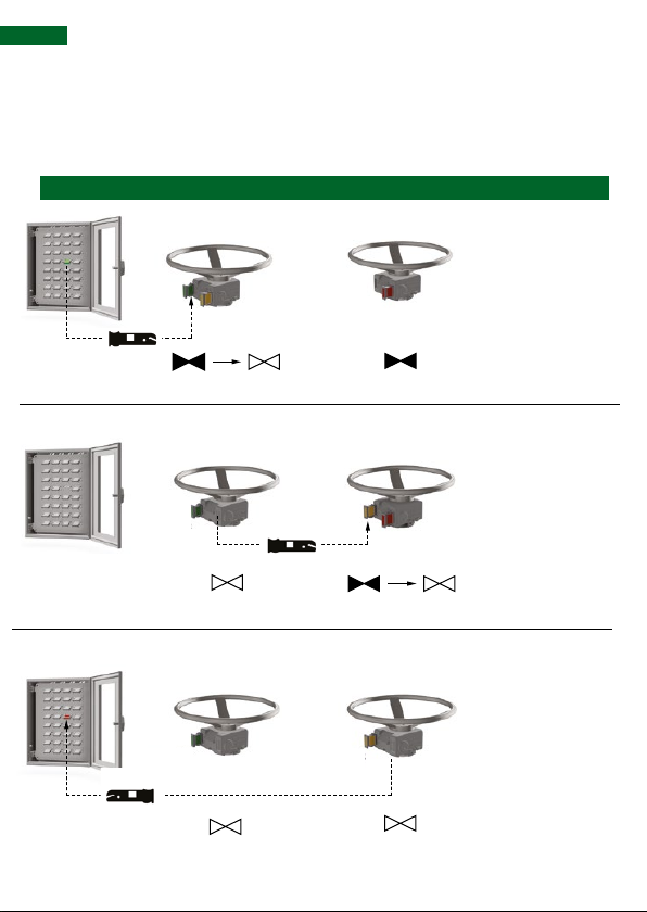
Lock A Lock BKey cabinet Situation
Basic principles of valve interlocking
Green start
key from key
cabinet to
lock A
Yellow switch
key from
lock A to lock B
Red end key
from lock B to
key cabinet
Operable Locked closed
Operable
Locked open
Locked open Locked open

support: +31 (0)172 471 339
7
1
1
Basic principles
Key code on lock
Key code on key
Position for open key
Position for close key
>Green start key is inside the key cabinet in its
dedicated position (green = normal operation)
> Yellow keys in locks in the eld are trapped and
designated to stay in the eld
> A key only ts in lock with the same key code
>Insert key to unlock, operate and after operating
remove the other key
>After last valve operation, insert end key into
dedicated position in the key cabinet.
Quick Fix Guide www.netherlocks.com/support
8
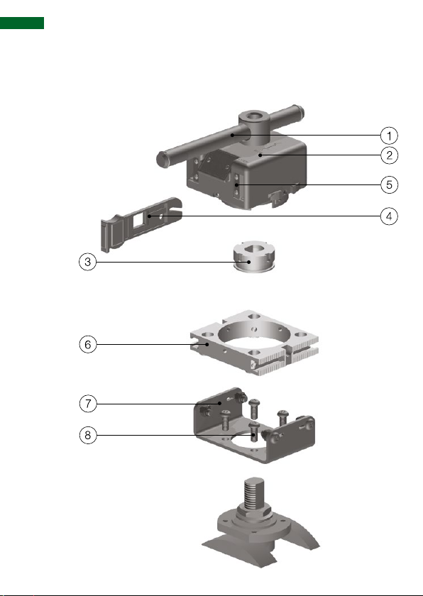
NDL exploded view
Valve interlock components

support: +31 (0)172 471 339
9
Ninety degree lock, for all types of lever operated valves.
Legend
1. AISI 431 sliding lever for optimum exibility
2. AISI 316 body
3. AISI 316 Adaptor - purpose machined - with 4 keyways
4. Linear key for operator friendly use
5. Key slots protected with self sealing weather strips
6. Mounting plate to connect bracket to interlock
7. AISI 316 bracket - purpose machined
8. Fixing means
Basic principles
Quick Fix Guide www.netherlocks.com/support
10
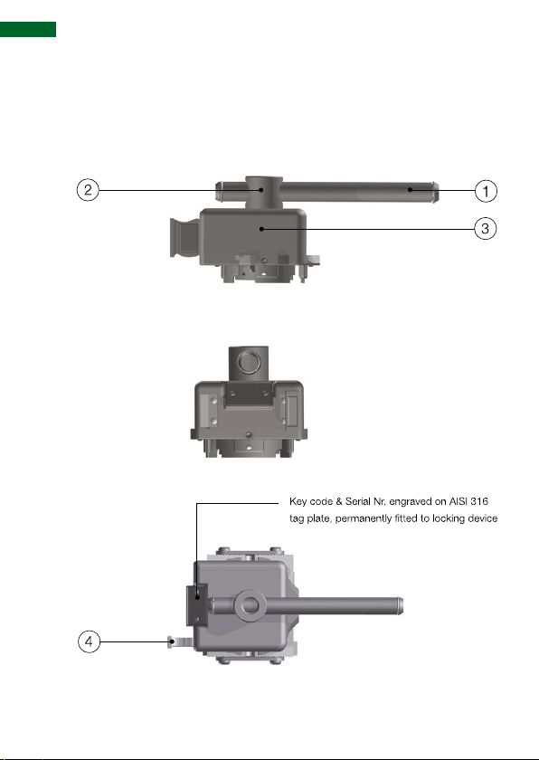
NDL GA drawing
Valve interlock components

support: +31 (0)172 471 339
11
Legend
1. Lever
2. Tube NDL
3. Lock body NDL
4. Operating key
Dimensions
Length (mm) 133
Width (mm) 115
Height (mm) 107
Mass of lock (kg)* 2,9
Lever sizes (mm) Dierent lever sizes from 230 to
730
* Without bracket- and adaptor
Quick Fix Guide www.netherlocks.com/support
12
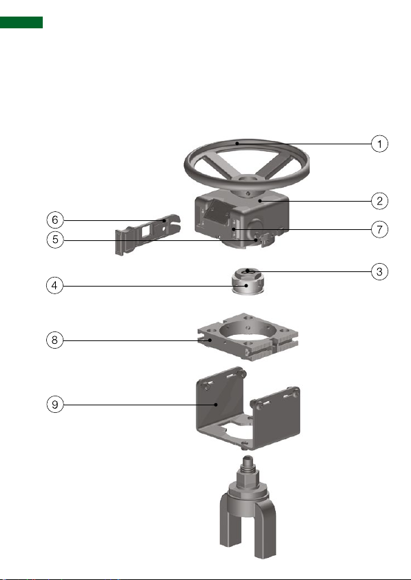
Valve interlock components
MRL exploded view

support: +31 (0)172 471 339
13
Multi rotation lock, for all types of handwheel and gear
operated valves.
Legend
1. CS powder coated hand wheel / optional AISI 316
2. AISI 316 body
3. Original nut will be used if possible
4. AISI 316 Adaptor - purpose machined - with 4 keyways
5. Easy to set and reset counters behind counter cover plate
6. Linear key
7. Key slots protected with self sealing weather strips
8. Mounting plate to connect bracket to interlock
9. AISI 316 bracket - purpose machined
Basic principles
Quick Fix Guide www.netherlocks.com/support
14
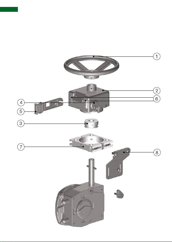
MRL on gearbox exploded view
Valve interlock components

support: +31 (0)172 471 339
15
Legend
1. CS powder coated hand wheel
2. AISI 316 body
3. AISI 316 adaptor - purpose machined - with 4 keyways
4. Easy to set and reset counters behind counter cover plate
5. Linear key
6. Key slots protected with self sealing weather strips
7. Mounting plate to connect bracket to interlock
8. AISI 316 purpose machined bracket
Basic principles
Quick Fix Guide www.netherlocks.com/support
16
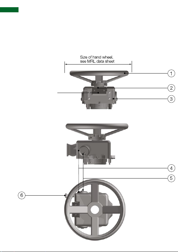
MRL GA drawing
Valve interlock components
Key code & serial
number engraved
on AISI 316 tag
plate, permanently
tted to locking
device

support: +31 (0)172 471 339
17
Legend
1. Handwheel
2. Tube
3. Lock body
4. Adjustment cover
5. Tamper proof M6 screw
6. Operating key
Basic principles
Dimensions MRL-S (small type)
Length (mm) 133
Width (mm) 115
Height (mm) 82
Mass of lock (kg)* 3
Handwheel sizes Dierent sizes between 200 and 700
Max. valve spindle diameter (mm) 26
* Without bracket, adaptor and hand wheel
Dimensions MRL-L (Large type)
Length (mm) 152
Width (mm) 144
Height (mm) 100
Mass of lock (kg)* 4.7
Handwheel sizes Dierent sizes between 380 and 700
Max. valve spindle diameter (mm) 68
* Without bracket, adaptor and hand wheel

Quick Fix Guide www.netherlocks.com/support
18
1. Key code open key
2. Key code close key
3. System tag number
4. Serial number (netherlocks-year.serialnumber)
Interlock tag plates
Table of contents


