Neumann.Berlin KH 805 User manual

· . · ·
()/- · - · @. · ..
KH
A S
. / . B M™
Operating Manual
Bedienungsanleitung
Manual Utilisateur
Manual de Operación

KH 805 | 1
Important safety instructions ...............................................2
The KH 805 subwoofer .....................................................4
Delivery includes ..........................................................4
Product overview ..........................................................5
Installing and connecting the KH 805 ........................................7
Preparing the subwoofer ...............................................7
Preparing the room....................................................7
Setting up the subwoofers..............................................8
Connecting the subwoofer.............................................10
Mounting the subwoofer electronics externally...........................14
Using the KH 805 .........................................................15
Switching the subwoofer on/o ........................................15
Calibrating the subwoofer.............................................15
Compensating for larger time of flight (TOF) dierences ..................18
Using the bass management ...........................................18
Setting the replay level of the subwoofer................................19
Activating ground lift .................................................20
Cleaning and maintaining the subwoofer ................................21
Troubleshooting ..........................................................21
Specifications ............................................................22
Accessories ..............................................................24
Manufacturer Declarations .................................................25
Technical information & glossary ...........................................26
Contents
Appendix
System block diagram....................................................I
Pin assignment of the XLR socket .........................................I
Pin assignment of the REMOTE CONTROL socket ............................I
Acoustical measurements .............................................II-IV
2| KH 805
Important safety instructions
1. Read these instructions.
2. Keep these instructions. Always include these instructions when passing the product on
to third parties.
3. Heed all warnings.
4. Follow all instructions.
5. Do not use this apparatus near water.
6. Only clean the product when it is not connected to the mains power supply. Clean only
with a dry cloth.
7. Always ensure a free air flow around the cooling fins on the rear of the product. Do not
block any ventilation openings. Install in accordance with the manufacturer’s instructions.
8. Do not install near any heat sources such as radiators, heat registers, stoves, or other
apparatus (including amplifiers) that produce heat.
9. Do not defeat the safety purpose of the polarized or grounding-type plug. A polarized plug
has two blades with one wider than the other. A grounding type plug has two blades and
a third grounding prong. The wide blade or the third prong are provided for your safety.
If the provided plug does not fit into your outlet, consult an electrician for replacement of
the obsolete outlet.
10. Protect the power cord from being walked on or pinched, particularly at plugs, conveni-
ence receptacles, and the point where it exits from the apparatus.
11. Only use attachments/accessories specified by the manufacturer.
12. Use only with the cart, stand, tripod, bracket, or table specified by the manu-
facturer, or sold with the apparatus. When a cart is used, use caution when
moving the cart/apparatus combination to avoid injury from tip-over.
13. Unplug this apparatus during lightning storms or when unused for long periods of time.
14. Refer all servicing to qualified service personnel. Servicing is required when the appara-
tus has been damaged in any way, such as power supply cord or plug is damaged, liquid
has been spilled or objects have fallen into the apparatus, when the apparatus has been
exposed to rain or moisture, does not operate normally, or has been dropped.
15. To completely disconnect this apparatus from the AC mains, disconnect the power supply
cord plug from the AC receptacle.
16. WARNING: To reduce the risk of fire or electric shock, do not expose this apparatus to rain
or moisture.
17. Do not expose this equipment to dripping or splashing and ensure that no objects filled
with liquids, such as vases, are placed on the equipment.
18. The mains plug of the power supply cord shall remain readily accessible.
The label shown on the right is attached to the rear of
the product.
The symbols on this label have the following meaning:
Presence of uninsulated dangerous voltage within the product’s enclo-
sure that may be of sucient magnitude to constitute a risk of fire or
electric shock.
Never open the product or remove the grilles fitted to the product as
there is a risk of electric shock. There are no user serviceable parts
inside. Refer servicing to your Neumann service partner.
Read and follow the safety and operating instructions contained in the
operating manual.
Hazard warnings
on the rear of
the product

KH 805 | 3
• Ensure that the room in which you use this product is wired in accordance with the local
electrical code and checked by a qualified inspector.
• Only use the product indoors.
• Do not install the product in hot, humid, or excessively dusty locations, in direct sunlight or
in locations where it is exposed to externally generated vibrations.
• Do not place burning objects (e.g. candles) on top of or near the product.
• If condensation has formed on the product, e.g. because it was moved from a cold environ-
ment to a warm one, allow the product to acclimatize to room temperature before using it.
• Do not overload wall outlets and extension cables as this may result in fire and electric
shock.
WARNING
Danger of hearing damage due to sudden high sound pressure levels!
Audio signals that are present at switch-on of the product or that can be present during
operation, can create sudden, very high sound pressure levels which can damage your
hearing.
XAlways lower the output level of the audio source before connecting it to the subwoofer
or starting it (pressing “play”).
This subwoofer can be used for commercial purposes. Commercial use is subject to the rules
and regulations of the trade association responsible. Neumann, as the manufacturer, is there-
fore obliged to expressly point out possible health risks arising from use. This subwoofer is
capable of producing sound pressure levels exceeding 85 dB(A) SPL. This is the sound pres-
sure corresponding to the maximum permissible level which is by law (in some countries)
allowed to aect your hearing for the duration of a working day (8 hours). It is used as a basis
according to the specifications of industrial medicine. Higher sound pressure levels and/or
longer durations can damage your hearing.
At higher sound pressure levels, the duration must be shortened in order to prevent hearing
damage. The following are signs that you have been subjected to excessive sound pressure
levels for too long a time.
• You can hear ringing or whistling sounds in your ears.
• You have the impression (even for a short time only) that you can no longer hear high fre-
quencies (temporary threshold shift).
WARNING
Interference due to magnetic fields!
This product generates stronger permanent magnetic fields that can interfere with cardiac
pacemakers and implanted defibrillators (ICDs).
XAlways maintain a distance of at least 4" (10 cm) between the subwoofer and the cardiac
pacemaker or implanted defibrillator.
Intended use of the product includes:
• having read this operating manual, especially the chapter “Important safety instructions”,
• using the product within the operating conditions and limitations described in this operat-
ing manual.
“Improper use” means using the product:
• other than as described in this operating manual, or
• under operating conditions which dier from those described herein.
This will invalidate the guarantee.
Installation
High sound
pressure levels
Magnetic fields
Intended use

4| KH 805
The KH 805 subwoofer
Thank you for purchasing a Neumann subwoofer. Neumann subwoofers are designed to com-
plement Neumann’s extensive range of monitors. They can be used in music, broadcast, and
post production studios for tracking, mixing, mastering, and home recording. They can be
positioned next to a wall or flush mounted into a wall, and can be mixed freely in multi-chan-
nel systems with other loudspeakers and subwoofers from the Neumann Studio Monitor Sys-
tems range.
The built-in 2.1 / 0.1 Bass Manager can be used in many ways as there are four routing modes
to ensure maximum flexibility when using the subwoofer - see “Uses” below. Fourth order
crossovers and flexible acoustical controls allow for seamless system integration and the bass
management function can be remotely controlled.
State-of-the-art circuitry design and the specially developped long excursion bass driver have
been used to ensure the most accurate sound reproduction possible. Neumann products are
designed for longevity so we hope you enjoy many happy years of using this product.
Uses
• Bass extension for loudspeakers
• Increasing the maximum SPL of loudspeakers
• Decreasing harmonic and intermodulation distortion of loudspeakers
• Reproducing the LFE channel
• Reproducing the “Sub” signal of a bass managed multichannel source
• Making a Plane Wave Bass Array™ system
• Working as an extension for KH810, KH870 and KH805 subwoofer systems
Delivery includes
1 KH 805 subwoofer
3 Mains cables (European, UK and US version)
1 Operating manual
1 Supplement “Getting Started Quickly”
The current operating manual as well as the supplement “Getting Started Quickly” can also be
downloaded from the “Downloads” area on the product page at www.neumann.com.
Note that imperial dimensions are approximate.
KH 805 | 5
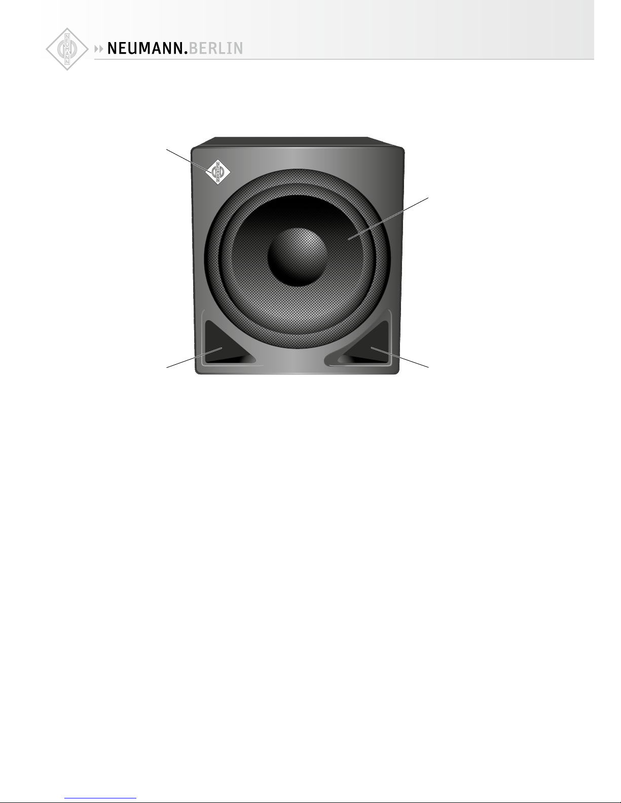
Product overview
1
2
3 3
1 Neumann logo
2 Metal grille
3 Bass reflex ports

6| KH 805
1
A 0 9B
JK LMHI
E
F
G
8
8
4
5
6
7
D
C
4 MAINS VOLTAGE SELECTION switch
5 MAINS POWER switch
6 Grounding point
7 IEC mains socket with protective ground contact
8 Ventilation openings
9 LOW CUT potentiometer
0 Potentiometers
PARAMETRIC EQUALIZER | GAIN
PARAMETRIC EQUALIZER | Q
PARAMETRIC EQUALIZER | FREQUENCY
A PARAMETRIC EQUALIZER switch
B INPUT GROUND LIFT switch
C Sockets
INPUT | RIGHT/LFE/DAISY CHAIN
INPUT | LEFT
D Sockets
OUTPUT | DAISY CHAIN
OUTPUT | RIGHT
OUTPUT | LEFT
E REMOTE CONTROL socket
F BASS MANAGEMENT switch
G BASS MANAGEMENT LED
H SUBWOOFER GAIN | OUTPUT LEVEL switch
I POWER ON LED
• green = on
• red = protection active
J SUBWOOFER GAIN | INPUT GAIN potentiometer
K RIGHT CHANNEL INPUT MODE switch
L SUBWOOFER PHASE switch
M SUBWOOFER PHASE switch

KH 805 | 7
Installing and connecting the KH 805
Have the product installed and connected by a specialist. Due to his/her technical training,
know-how and experience as well as knowledge of relevant provisions, regulations and stan-
dards, the specialist must be able to assess assigned tasks, recognize potential hazards and
ensure appropriate safety measures. The following safety and mounting instructions are
addressed to this specialist.
CAUTION
Danger of injury and material damage due to tipping/dropping of the product!
If improperly mounted, the product and/or the mounting hardware (e.g. rack) can tip over
or drop down.
X
Always have the product mounted by a qualified specialist according to local, national
and international regulations and standards.
X
Use the mounting systems recommended by Neumann and always provide sucient addi-
tional protection against tipping or dropping by means of safety wires.
CAUTION
Damage to the product due to overheating!
If air cannot circulate properly through the ventilation openings 8on the rear of the prod-
uct, the power amplifiers may overheat leading to premature activation of the thermal pro-
tection system which limits the maximum output level of the subwoofer. In rare cases, dam-
age to the product may also occur.
XNever cover the ventilation openings 8.
XWhen installing the product into tight spaces such as wall recesses, maintain an air gap
of at least 2" (5 cm) around the subwoofer’s backplate to ensure a free air flow through
the ventilation openings.
For information on installation, please refer to the supplied “Getting Started Quickly”
supplement. This will help you set up the subwoofers and loudspeakers in a way that
will give you the best acoustic performance from the system. For further information on
setting up subwoofers and loudspeakers, please refer to the “Questions & Answers”
section at www.neumann.com.
Preparing the subwoofer
CAUTION
Risk of staining surfaces!
Some surfaces treated with varnish, polish or synthetics may suer from stains when they
come into contact with other synthetics. Despite a thorough testing of the synthetics used
by us, we cannot rule out the possibility of staining.
XDo not place the KH 805 on delicate surfaces.
The bottom of the subwoofer features rubber feet which reduce the risk of scratching the sur-
face and the subwoofer cabinet, and acoustically isolate the subwoofer from the surface.
If you want to hide the subwoofer:
XUse a thin open weave cloth. To provide visual cover, you can use two layers of the cloth.
Preparing the room
X
Arrange all acoustically relevant surfaces and objects symmetrically on either side of the
listening axis of the room (left/right).
XMinimize the sound that is reflected back to the listening position by using angled surfaces
and/or acoustical treatment.
This product has been optimized for use in recording studios. In order to avoid aecting
the quality of reproduction, make sure that the product is used in an EMC environment.

8| KH 805
Setting up the subwoofers
Choosing the type of set up
The bass reflex ports are located on the front panel of the subwoofer, allowing the subwoofer
to be either set up in a room or flush mounted into a wall recess.
Flush mounting the subwoofer into a wall recess oers the following advantages:
• A solid wall boosts the level of the subwoofer in the room which can be compensated by
reducing the output level of the subwoofer. This also reduces distortion resulting in a cleaner
sound reproduction.
• Reflections from the wall behind the subwoofer are eliminated so that the frequency
response becomes smoother.
• The subwoofer does not occupy space in the room.
If you want to flush mount the subwoofer into a wall recess:
X
Have the wall constructed by an experienced acoustical engineer. At least the following points
should be observed:
• The wall should be solid (stone, brick, concrete, several layers of gypsum or MDF).
• Ensure a free air flow through the ventilation openings 8on the rear of the subwoofer
(see warning note on page 7) or remote locate the subwoofer electronics using the
Neumann REK 3 remote electronics kit and an SC cable (available in dierent lengths, see
“Accessories” on page24).
Using one or several subwoofers
XUse ...
one subwoofer several subwoofers
... if your room does not oer sucient
space for several subwoofers.
... if you need to move left and right
along the mixing console, or if there are
several listening positions along a large
format mixing console.
... if you require a higher output power
or less distortion with the same output
power.
... to suppress lateral modes or cross
modes in the room by means of a Plane
Wave Bass Array (PWBA™).
... if many smaller cabinets are easier to
position than one large cabinet.
To reduce low-frequency distortion, the uncalibrated output level of your subwoofer
should always be higher than the output level of your loudspeakers. We recommend
using arrays with several subwoofers, in which case the uncalibrated maximum output
level of the subwoofer array should also be higher than the maximum output level of all
the loudspeakers in the system. The subwoofers can then be calibrated to a lower out-
put level resulting in lower distortion and correspondingly cleaner low-frequency
reproduction.
For information on building a balanced system, please refer to the “Product Selection
Guide” at www.neumann.com.

KH 805 | 9
Positioning the subwoofers
Regardless of whether you are setting up one or several subwoofers:
X
Always ensure that the distance dwall between the wall behind the subwoofer and the sub-
woofer’s front is less than 0.8 m.
If you are setting up one subwoofer:
XPosition the subwoofer against the front wall, slightly left or right of the middle of the front
wall and between the left and right loudspeakers.
If you are setting up several subwoofers as a Plane Wave Bass Array™(PWBA™):
XUse two to four subwoofers for smaller rooms and three to four subwoofers for larger rooms.
XSet up the subwoofers along the front wall within half a wavelength of each other. The max-
imum spacing of the subwoofer cabinets is determined by the setting of the routing mode
(see page 19):
Setting Max. spacing of the subwoofer cabinets
RIGHT approx. 2 m (6'6")
LFE (120 Hz) approx. 1.4 m (4'6")
LFE (WIDE) approx. 1.4 m (4'6")
DAISY CHAIN depends on setting of first subwoofer
If you observe the stated spacing, the subwoofers form a cylindrical source and generate
a plane wave down the room, a so-called Plane Wave Bass Array™(PWBA™). The PWBA™
reduces stationary waves between the side walls, improves the bass reproduction and
suppresses lateral room resonances.
For examples of set up positions and distances, please refer to the supplied “Getting
Started Quickly” supplement.
You can correct excessive low frequency energy in the room using the potentiometer
SUBWOOFER GAIN| INPUT GAIN Jand the switch SUBWOOFER GAIN | OUTPUT LEVEL H
(cf. page27).
If you set up several subwoofers, you can utilize their mutual coupling to achieve an acoustical
gain. The following acoustical gains are possible:
Number of subwoofers Acoustical gain
10.0 dB
26.0 dB
39.5 dB
412.0 dB
dwall
Utilizing the
acoustical gain
10 | KH 805
Positioning and orienting subwoofers and loudspeakers
Subwoofers are omni-directional in their typical pass band as the generated wavelength is
long compared to the surface producing the sound, therefore it does not matter in which direc-
tion the subwoofer is oriented when placed in the listening environment.
For your loudspeakers, however, an accurate positioning and orientation is vital.
XPosition your loudspeakers as follows:
System Position and orientation
2.0 (stereo) ±30°
5.1 ITU-R BS.775-1:
0°, ±30°, ±110° (±10°)
(center, front left/right, surround left/right)
ANSI/SMPTE 202M:
0°, ±22.5°, arrays to the surround left and to the surround right,
plus optional subwoofer(s)
6.1 as 5.1 systems plus 180° (back center)
7.1 0°, ±30°, ±90°, ±150°
(center, front left/right, side left/right, back left/right)
For detailed information on the positioning and orientation of your loudspeakers, please refer
to the operating manuals of the loudspeakers.
If your subwoofers cannot be placed at the same distance from the listening position as the
loudspeakers, time-of-flight dierences will occur.
XAvoid distance dierences of > 2m (6'6").
X
Compensate for time-of-flight dierences as described in the chapter “Calibrating the phase”
on page 17.
Connecting the subwoofer
Connecting the subwoofer to an audio source
X
Use balanced XLR cables to connect the corresponding sockets INPUT Cof the KH 805 to
the audio source.
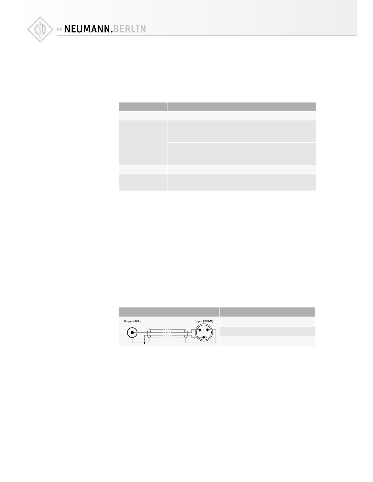
XUse an XLR adapter (not supplied) to connect unbalanced cables (e.g. RCA cables).
Use the
following wiring if you want to make your own XLR adapter:
Wiring Pin Signal
Output (RCA) Input (XLR-M)
1Audio ground
2Signal +
3Signal -
The level delivered by devices with RCA outputs (-10 dBV) is usually less than the studio level
(+4 dBu):
X
If necessary, use active unbalanced-to-balanced converters in order to be able to connect
devices with unbalanced signals.
Connecting
unbalanced
cables
KH 805 | 11
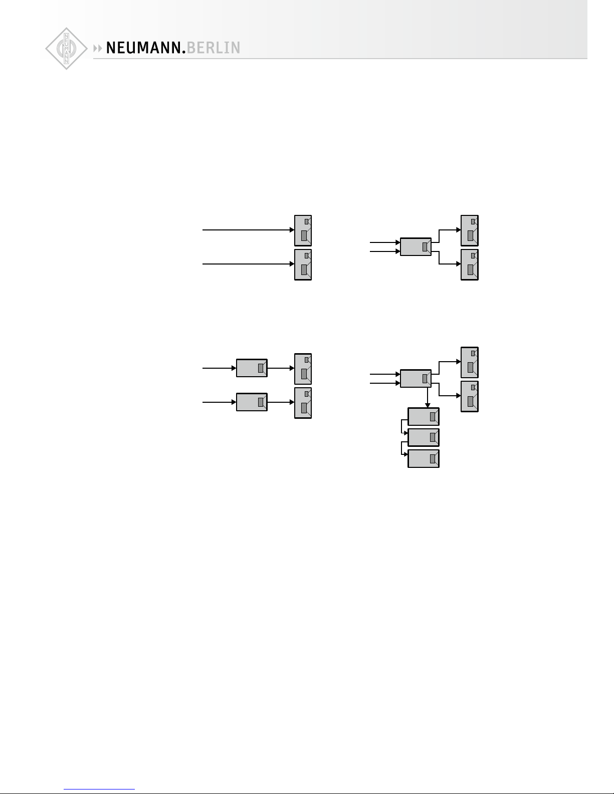
Connecting loudspeakers to the subwoofer
For a simplified representation, the following connection examples show small loudspeakers
in combination with the KH 805 subwoofer. Each of the examples only shows one possible
combination of loudspeakers and subwoofers. For information on building a balanced system,
please refer to the “Product Selection Guide” at www.neumann.com.
XUse balanced XLR cables to connect the corresponding sockets OUTPUTDof the subwoofer
to the input sockets of the loudspeakers, as shown in the following diagrams.
Stereo: two loudspeakers Full range stereo (bass managed): two
loudspeakers and one subwoofer
L
R
L
Sub
Right Channel Input Mode: Right
R
Full range stereo: two loudspeakers
and stereo subwoofers Full range stereo (bass managed): two
loudspeakers and multiple subwoofers
L
Sub L
Sub R
Right Channel Input Mode: Right
R
LSub 1
Sub 2
Sub 3
Sub 4
Right Channel
Input Mode: Right
Daisy Chain
Daisy Chain
Daisy Chain
R
Additional subwoofers can be used for two
things:
1. Increasing max SPL below 80 Hz
2. Setting up a Plane Wave Bass Array (many
small subwoofers in a line)
Stereo systems

12 | KH 805
Multichannel system without
bass management in the source
equipment
Multichannel system with bass
management in the source
equipment
Hybrid bass managed L/R
multichannel system
L
C
R
Ls
Rs
L
C
R
Ls
Rs
Sub Sub 1
Optional extra
subwoofers
depending on
size of main
loudspeakers
Sub 2
Sub 3
Sub 4
LFE (120 Hz)
Daisy Chain
Daisy Chain
Daisy Chain
L
C
R
Ls
Rs
L
C
R
Ls
Rs
Sub Sub 1
Optional extra
subwoofers
depending on
size of main
loudspeakers
Sub 2
Sub 3
Sub 4
LFE (WIDE)
Daisy Chain
Daisy Chain
Daisy Chain
L
R
C
Ls
Rs
L
R
C
Ls
Rs
LFE SubLFE
LFE (120 Hz)
Main Sub
Right
Additional subwoofers can be added
to the L/R Sub and/or LFE Sub using
the setting “Daisy Chain”
Full range large multichannel system with
bass management in the source equipment Full range large multichannel system
L
C
R
Lb
Rb
L
C
R
Lb
Rb
LFE Sub 1
LFE over three
subwoofers
or separate
“LFE only“ subs
Sub 2
Sub 3
Sub 4
LFE (WIDE)
Daisy Chain
Daisy Chain
Daisy Chain
Ls
Rs
Ls
Rs R
Ls
Rs
R
Ls
Rs
LFE Sub 1
Optional extra
subwoofers
Sub 2
Sub 3
Sub 4
LFE (WIDE)
Right
Example: KH 420
positioned above
2x KH 805
See next page for
setup details
Daisy Chain
Daisy Chain
Daisy Chain
Daisy Chain
C
C
LL
Three subwoofers reproducing one channel adds up
to 9.5 dB of acoustical gain which is very close to
the 10 dB of gain required for the LFE channel.
Multichannel
systems
KH 805 | 13
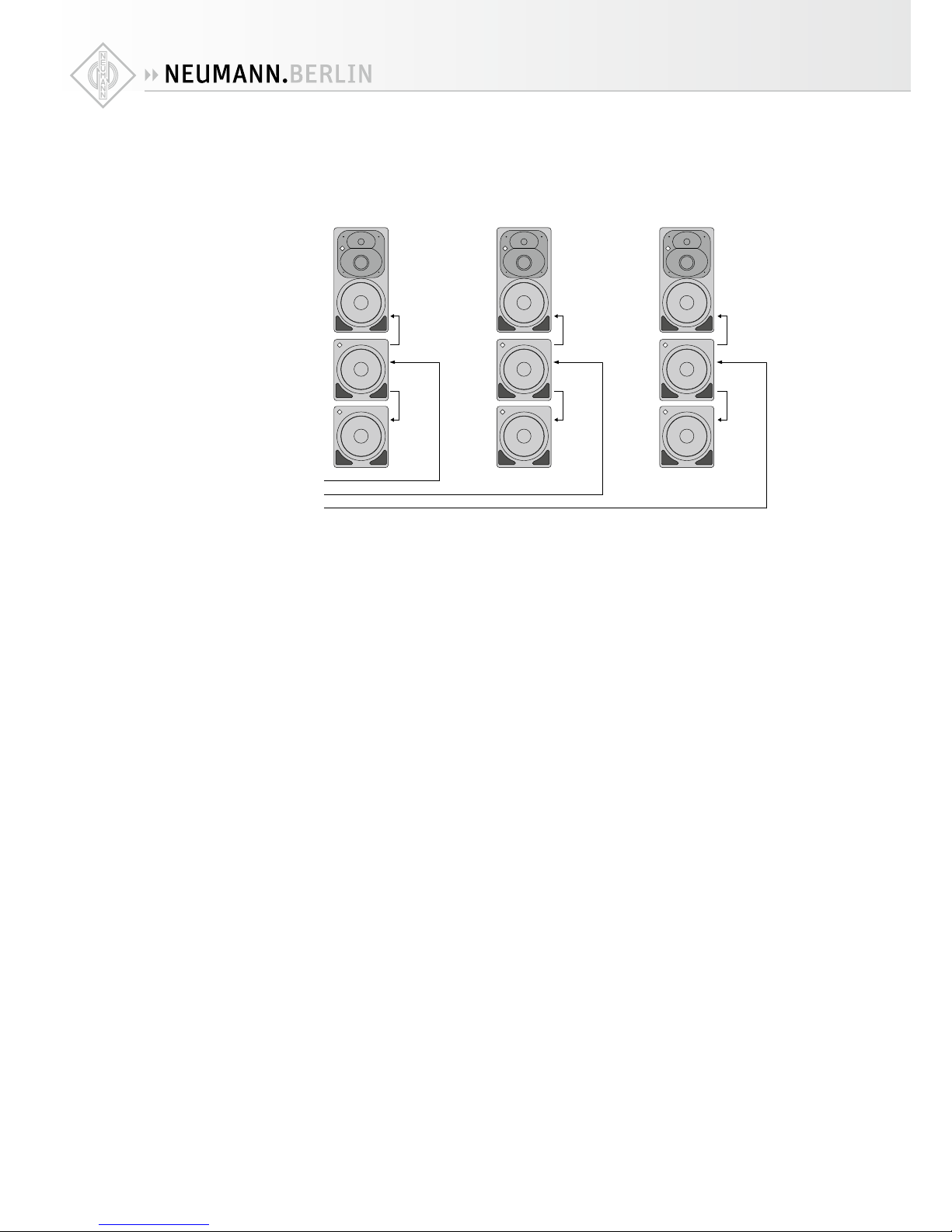
Using subwoofers in a 4-way system
To build a larger system:
XInstall the subwoofers and loudspeakers like columns:
Left
Right
Center
INPUT RIGHT
OUTPUT RIGHT
INPUT
DAISY CHAIN
OUTPUT
DAISY CHAIN
INPUT
INPUT RIGHT
OUTPUT RIGHT
INPUT
DAISY CHAIN
OUTPUT
DAISY CHAIN
INPUT
INPUT RIGHT
OUTPUT RIGHT
INPUT
DAISY CHAIN
OUTPUT
DAISY CHAIN
INPUT
XConnect the channels Left, Center, Right of your audio source to the subwoofers according
to their physical position (see diagram above):
•Connect the channel Left to the socket INPUT | RIGHT Cof the upper left subwoofer, con-
nect the channel Center to the socket INPUT | RIGHT Cof the upper center subwoofer
and connect the channel Right to the socket INPUT | RIGHT Cof the upper right sub-
woofer.
XSet the switch RIGHT CHANNEL INPUT MODE Kon all three upper subwoofers to RIGHT.
XIn each position (left, center, then right), connect the socket OUTPUT | DAISY CHAIN Dof
the upper subwoofer to the socket INPUT | DAISY CHAIN Cof the lower subwoofer.
X
Set the switch RIGHT CHANNEL INPUT MODE Kon all three lower subwoofers to DAISY CHAIN.
After calibrating the main loudspeakers, the subwoofers should be acoustically calibrated so
that they smoothly extend the bass response of their respective main loudspeaker down in
frequency from 80 Hz to below 20 Hz. There is no need to adjust the acoustical controls on
the lower subwoofers because the acoustical control settings made on the upper subwoofers
will be tracked by the lower subwoofers.
Finally, the LFE channel should be routed to the LEFT, CENTER and RIGHT outputs of the
source. The level of the LFE channel should then be adjusted in the source to give a 10 dB
higher level in the room compared to any one of the main channels.
Alternatively, separate subwoofers can be used to reproduce only the LFE channel.
For a stereo system, leave away the center loudspeaker and subwoofers, and ignore the LFE
comment above.
Do not use the subwoofer in parallel to the main loudspeakers by replaying the low frequen-
cies of the signal using both the subwoofer and the main loudspeakers. Doing it this way
leads to constructive and destructive interference where the responses overlap due to the
dierent phase responses of the drivers. The result is an uneven bass response in the room,
especially if you are moving around. Always connect the subwoofer in one of the ways shown
above.
14 | KH 805
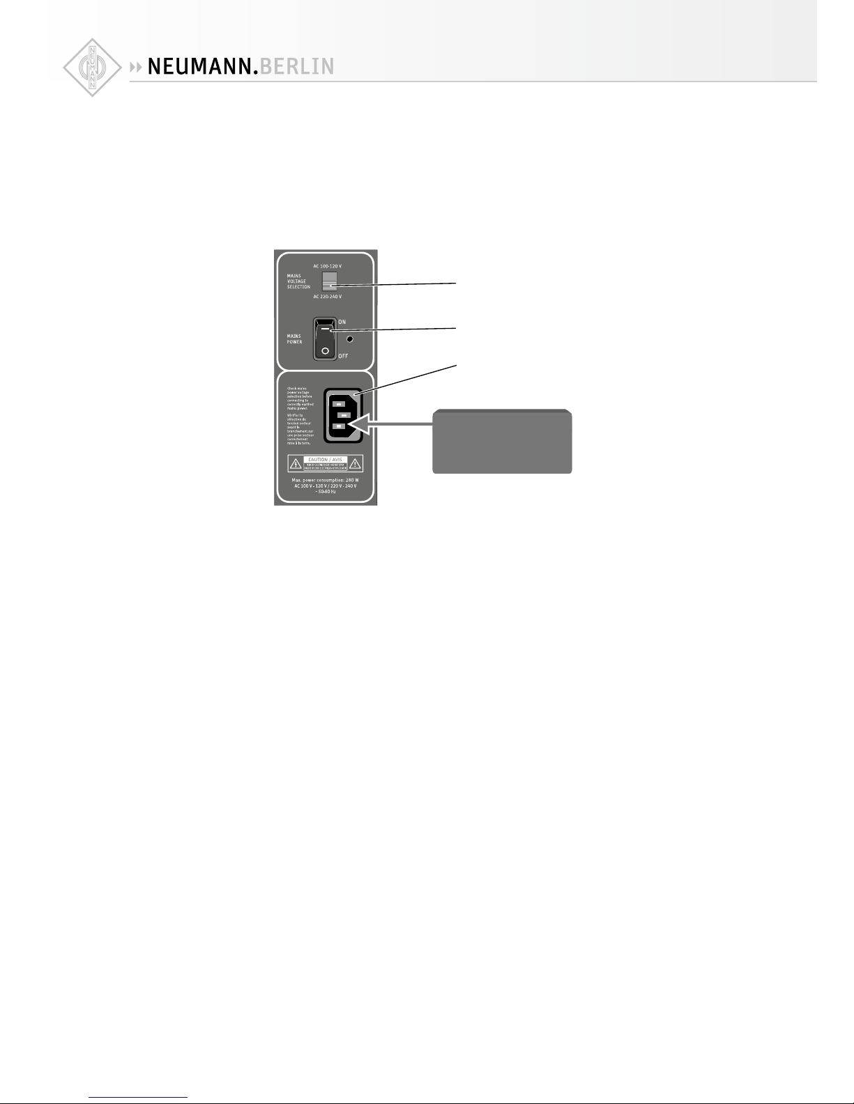
Connecting/disconnecting the subwoofer to/from the mains power supply
To connect the KH 805 to the mains power supply:
XMake sure that the switch MAINS POWER 5is set to “OFF”.
XMake sure that the switch MAINS VOLTAGE SELECTION 4is set to the correct position:
“AC 100/120 V” if your mains voltage is 100 V or 120V or
“AC 220/240 V” if your mains voltage is 220 V, 230 V or 240V.
XConnect the IEC connector of the supplied mains cable to the IEC mains socket 7.
Power Source
4
5
7
XConnect the mains plug of the mains cable to a suitable wall socket.
To disconnect the KH 805 from the mains power supply:
XSet the switch MAINS POWER 5to “OFF”.
XPull the mains plug out of the wall socket.
Mounting the subwoofer electronics externally
If you distribute the subwoofers around the room but wish to have centralized access to the
operating controls of the subwoofer electronics or if you set up your subwoofers so that easy
access to the subwoofer electronics is not possible, you can mount the latter externally:
XUse the Neumann REK3 remote electronics kit together with an SC cable (available in dier-
ent lengths, see “Accessories” on page24).
XProceed as described in the operating manual of the REK 3.

KH 805 | 15
Using the KH 805
Switching the subwoofer on/o
You can switch the KH 805 on and o using the switch MAINS POWER 5.
XSet the switch MAINS POWER 5 to:
• “ON” to switch the subwoofer on. The LED POWER ONIlights up red for 3 seconds, dur-
ing which the subwoofer is muted (see below). The LED POWER ONIthen lights up
green.
• “OFF” to switch the subwoofer o. The LED POWER ONIgoes o.
There is a three second delay before sound can be heard from the KH 805 and the loud-
speakers connected to the outputs in order to avoid noises (pops) from preceding
equipment switched on at the same time. Conversely, switching o the subwoofer
immediately mutes the audio.
Calibrating the subwoofer
Before using your system for the first time and whenever you change the physical conditions in
your studio, carry out the following steps:
XAdjust the frequency response and the level of the loudspeakers before calibrating the sub-
woofer (see the operating manual of the loudspeakers):
Application Recommended frequency response Comments
Studio flat A flat response brings good
translation
Film X-curve shape Cf. ANSI/SMPTE 202M:
the shape of the X-curve
depends on the size of the room
Home subjective evaluation Not necessarily a flat response,
a gently downward sloping
response with increasing
frequency is often preferred
All the loudspeakers in the system should have the same level at the listening position. This
is often measured using a pink noise test signal that is set to -18 dBFS (Europe) or -20 dBFS
(USA) on the mixing console’s output level meters and a sound level meter set to “C-weighted”
and “slow”.
On/o switching
using the switch
MAINS POWER 5
16 | KH 805
XCalibrate the frequency response, the phase and the acoustical level of the subwoofer.
To do so, choose one of the following methods:
1. Calibration using an acoustical measurement system
Calibrating the frequency response, phase and sound pressure level by means of an
acoustical measurement system should always be your first choice since it yields the
highest accuracy. This method is described below.
2. Calibration using Neumann test signals
In the absence of an acoustical measurement system, you can calibrate the settings of
your subwoofer using Neumann test signals (see page 17).
3. Calibration using music signals and an 80 Hz test signal
A calibration by means of music signals is also possible but should always be the last
choice. In this case, play an 80 Hz test signal from your source equipment to calibrate
the phase (see page 17).
If you are using several subwoofers, it is possible that the same setting is not valid for all
subwoofers.
XCalibrate each subwoofer separately.
However, note that daisy chained subwoofers will track the settings on the first subwoofer
in the daisy chain.
XIf necessary, move the subwoofer and/or the main loudspeakers.
XIf necessary, apply acoustical treatment to the source of any reflections.
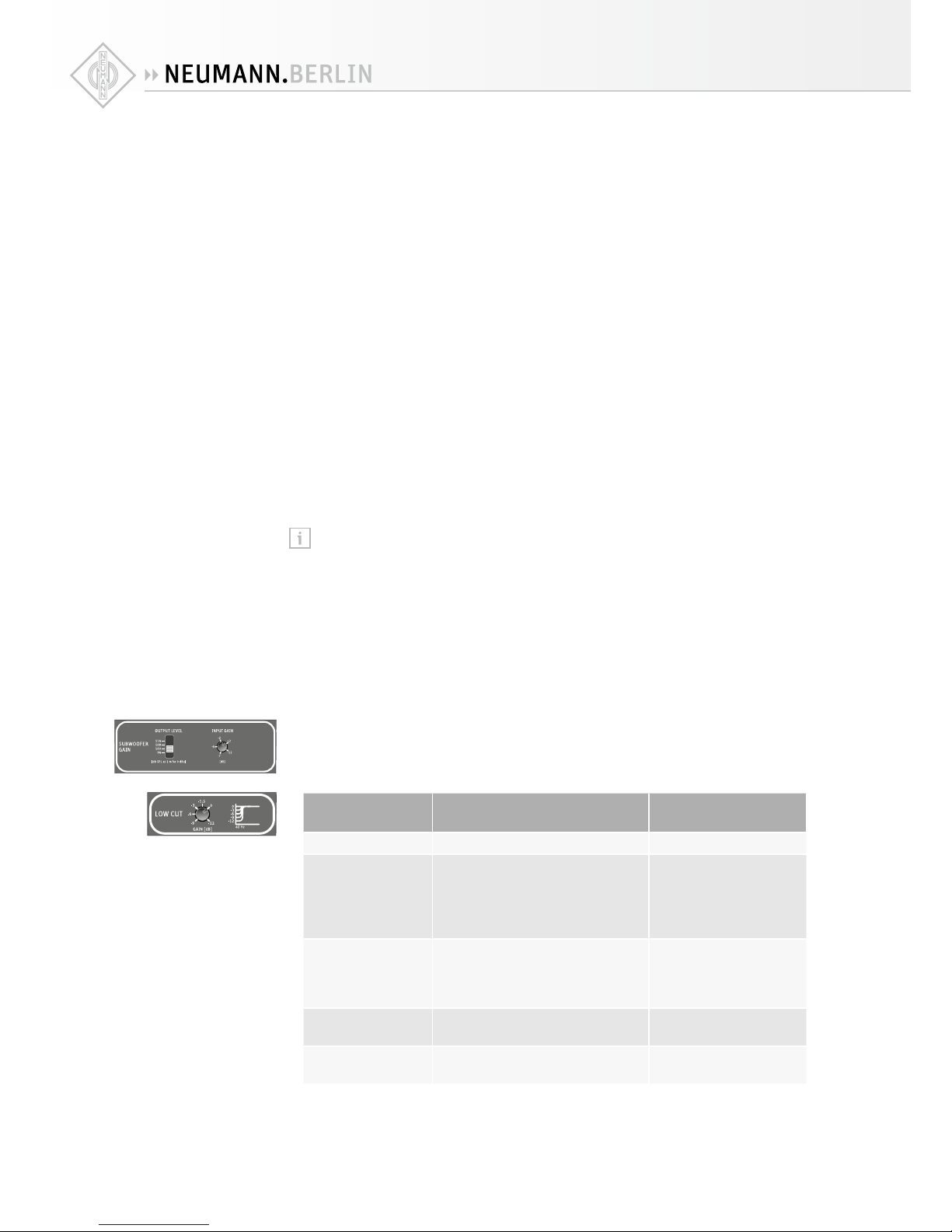
Calibration using an acoustical measurement system
The settings of the switch SUBWOOFER GAIN | OUTPUT LEVEL Hand the potentiometer
SUBWOOFER GAIN | INPUT GAIN Jrecommended in the following table are valid for
the following settings of your Neumann loudspeaker: INPUT GAIN: “0 dB” and OUTPUT
LEVEL: “100 dB SPL at 1m for 0 dBu”. For information on how to set your Neumann
loudspeaker, please refer to its operating manual. If the mentioned values cannot be set
on your loudspeaker, adjust the subwoofer accordingly.
The frequency response of a subwoofer depends on its position in the room and on the room
geometry. The same subwoofer installed in dierent positions in the same room may require
dierent acoustical control settings.
XAdjust the frequency response of the subwoofer at your listening position. To do so, proceed
as follows:
X
Make sure that the switch SUBWOOFER GAIN | OUTPUT LEVEL His set to “100 dB SPL at 1m
for 0 dBu”.
X
First, set the potentiometers SUBWOOFER GAIN | INPUT GAIN Jand LOW CUT 9to the
following settings. These settings can be used as a starting point for further adjustment:
Subwoofer position Setting of potentiometer
SUBWOOFER GAIN | INPUT GAIN J
Setting of potentiometer
LOW CUT 9
In a corner -8 dB -4 dB
Next to or flush
mounted in an
acoustically solid
wall (e.g. brick,
concrete)
-4 dB -2 dB
Next to or flush
mounted in an
acoustically soft
wall (e.g. gypsum)
-2 dB 0 dB
Free standing in an
untreated room
-2 dB 0 dB
Free standing in a
well-treated room
0 dB 0 dB
Calibrating the
frequency
response
KH 805 | 17
XCheck the frequency response at the listening position using your acoustical measurement
system:
• In case of acoustical loading in the low frequency range at the listening position, turn
the potentiometer LOW CUT 9 to the left. This reduces the output level of the subwoofer
towards lower frequencies.
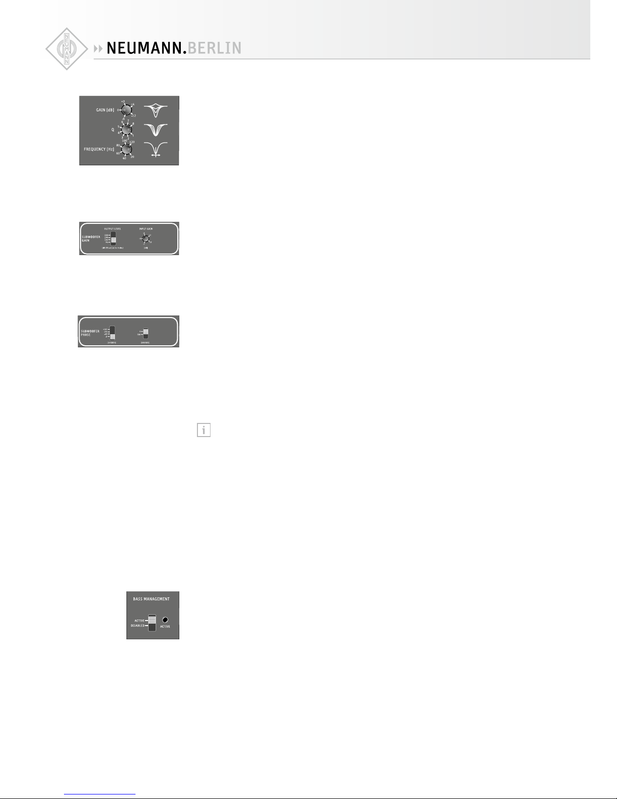
• Use the parametric equalizer 0to compensate for further nonlinearities in the frequency
response below 120 Hz caused by room modes and/or reflections.
XMeasure the subwoofer’s sound pressure level at the listening position.
XAdjust the sound pressure level of the subwoofer so that the level of the frequency response
of the subwoofer below 80 Hz corresponds to the level of the frequency response of the
loudspeakers above 80 Hz.
• To do so, use the potentiometer SUBWOOFER GAIN | INPUT GAIN Jand the switch
SUBWOOFER GAIN | OUTPUT LEVEL H. Make sure that the input signal is not too high.
XSet the phase using the left switch SUBWOOFER PHASE L. Values from -180ºto -315º can
be obtained by setting the right switch SUBWOOFER PHASE Mto “–180º” and by adding the
set value of the left switch SUBWOOFER PHASE L.
Example: To obtain a phase shift of –270º, set the right switch SUBWOOFER PHASE Mto
“–180º” and the left switch SUBWOOFER PHASE Lto “–90º”
XSet the left switch SUBWOOFER PHASE Lin combination with the right switch SUBWOOFER
PHASE Mto values of 0º, -45º, -90º, -135º, -180º, -225º, -270º, and -315º, until you have
found the setting that gives the lowest sound pressure level at the listening position at the
cut-o frequency of 80 Hz (180º phase shift between subwoofer and loudspeaker, maximum
level cancelation).
X
Set the right switch SUBWOOFER PHASE Mto the opposite position. The phase shift between
loudspeaker and subwoofer is now 0º. Check your subwoofer’s sound pressure level again
and, if necessary, readjust it so that it corresponds to the sound pressure level of the
loudspeakers.
Your system is now completely acoustically calibrated.
Note that any change of the low cut and parametric EQ influences the crossover
phase. Therefore, the phase and the level need to be recalibrated after changing the
low cut or parametric EQ settings.
Calibration using Neumann test signals
XDownload the Neumann test signals and the instructions for use (PDF file, in English) from
the KH 805 product page at www.neumann.com.
XFollow the steps described there.
Calibration using music signals and an 80 Hz test signal
X
Adjust the settings for the sound pressure level and the frequency response as described
above.
X
Calibrate the acoustical phase using an 80 Hz test signal. Check the settings of the sound
pressure level and frequency response by means of music signals you are familiar with.
• Connect the left front loudspeaker to the socket OUTPUT | LEFT D.
• Set the switch BASS MANAGEMENT Fto “ACTIVE”.
• Play an 80 Hz test tone from your source into the audio input INPUT | LEFT Cso that the
subwoofer and left loudspeaker are playing the tone.
• Set the rotary switch SUBWOOFER PHASE Lin combination with the switch SUBWOOFER
PHASE Mto values of 0º, -45º, -90º, -135º, -180º, -225º, -270º, and -315º, until you
have found the setting that gives the lowest sound pressure level at the listening position
at the cut-o frequency of 80 Hz (180ºphase shift between subwoofer and loudspeaker,
maximum level cancelation).
• Switch o the test signal at the source.
• Set the switch SUBWOOFER PHASE Mto the opposite position.
The phase shift between loudspeaker and subwoofer is now 0º.
Calibrating the
subwoofer level
Calibrating the
phase
18 | KH 805
X
Check the settings of the sound pressure level and frequency response by means of music
signals. Listen for a smooth extension of the frequency response of the main loudspeakers
down to 20 Hz.
To to this, proceed as follows:
X
Listen to music containing content down to 20 Hz. Activate and disable the bass management
by repeatedly moving the switch BASS MANAGEMENTFbetween the two positions. There
should be no increase or decrease in level between the lower cut o frequency of the moni-
tor and 80 Hz.
Compensating for larger time of flight (TOF) dierences
If the subwoofer is placed at a distance > 2 m (6'6") behind the loudspeakers with reference to
the listening position, the subwoofer’s integrated compensation settings will not suce.
X
Connect the KH 805 to an electronic time delay. Insert the electronic time delay into the
signal path between the sockets OUTPUT Dof the subwoofer and the input sockets of the
loudspeakers.
XCompensate for TOF dierences using the electronic time delay (see the operating instruc-
tions of the delay).
X
Alternatively use the D versions of our products with the input select switch set to Analog
Delayed, and then make an appropriate setting on the delay switches.
Using the bass management
X
For a two-channel stereo system set the switch RIGHT CHANNEL INPUT MODE Kto “RIGHT”.
XSet the switch BASS MANAGEMENT Fto “ACTIVE”.
The bass management is activated. This inserts a 4
th
order 80 Hz high pass filter into the
signal path of the audio outputs OUTPUT | LEFT and RIGHT Dand routes all audio signals
below 80 Hz to the subwoofer. The LED BASS MANAGEMENT Glights up green.
If you deactivate the bass management, the audio signal of the audio outputs OUTPUT | LEFT
and RIGHT Dis only reproduced by the loudspeakers. Use this function to prevent the low
frequency signal components of the main channels being reproduced by the subwoofer.
XSet the switch BASS MANAGEMENT Fto “DISABLED”.
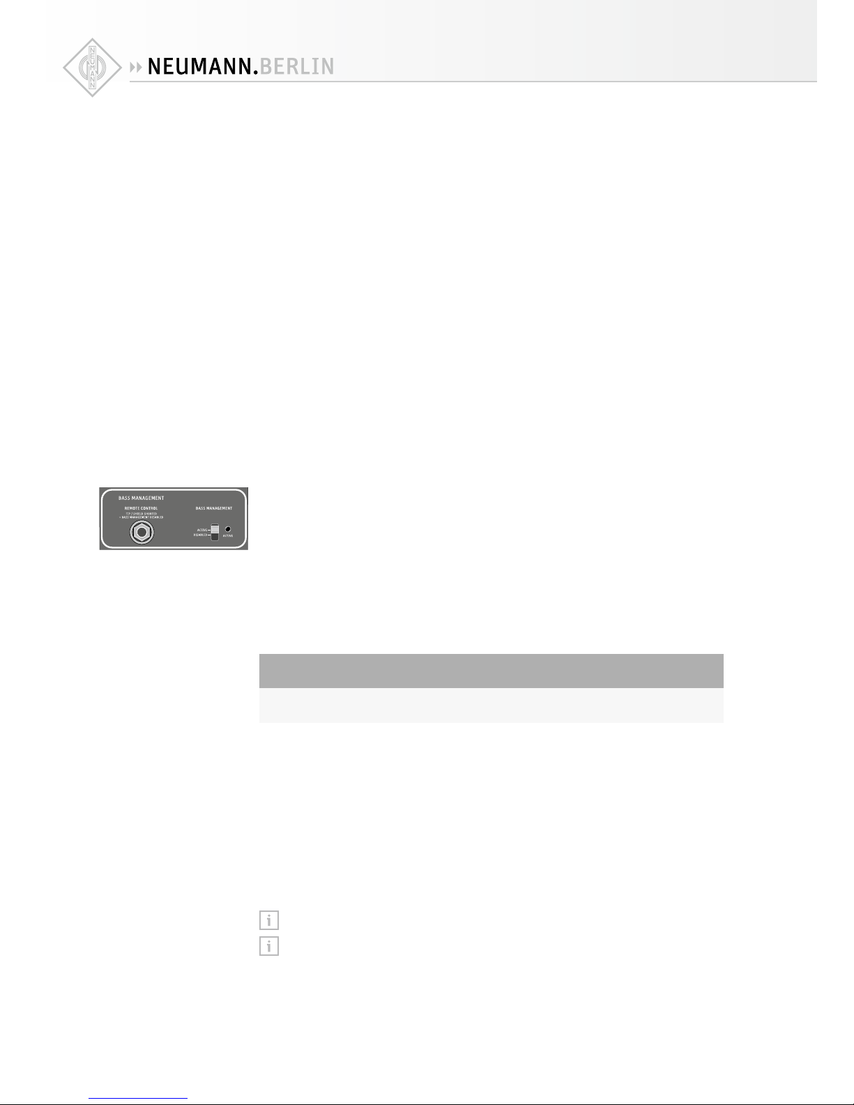
Remote-controlling the bass management
CAUTION
Material damage due to improper use of cables!
X
Do not connect instrument or amplifier outputs to this socket as this could damage the
KH 805 and/or the source device.
It is possible to activate and deactivate the bass management filters remotely when the sub-
woofer is used in a two-channel stereo system setup. This allows one to listen to the source as
if there is no subwoofer connected in the system because the loudspeakers play full range with
no filtering when the bass management is disabled.
XSet the switch BASS MANAGEMENT Fto “ACTIVE”.
XUse a “mono” jack cable to connect a switch to the REMOTE CONTROL socket E.
The switch should short the tip and sleeve together to bypass bass management.
If the switch has an LED indicator it can be used to show the status of the bass management
system because 9 V DC is present on the tip connection of the REMOTE CONTROL socket E.
There are some standard footswitches available at music retailers which can be used for this
functionality. Make sure to use a switch, as a pushbutton might not work properly.
Note that no audio passes down the remote control cables, only a control signal.
The pin assignment of the socket REMOTE CONTROL Ecan be found at the end of this
operating manual.
Compensating for TOF
dierences by means of an
electronic time delay

KH 805 | 19
Setting the replay level of the subwoofer
This mode should be used when the signal has not been encoded already. Do not use this mode
when playing back DVDs, Blu-ray disks or if there is a bass manager before the subwoofer. The
LFE channel should be replayed at a level 10 dB higher than the main channels. The level can
be set in the monitoring matrix (console or external), or by setting an appropriate output level
on the subwoofer.
XConnect the LFE channel to the socket INPUT | LFE Cof the KH 805.
XSet the switch RIGHT CHANNEL INPUT MODE Kto “LFE (120 Hz)”.
XCalibrate the frequency response of the subwoofer to be flat.
XMeasure the SPL of one of the main channels using pink noise and a sound level meter set to
“C-weighted” and “Slow”.
X
Measure the SPL of the LFE channel using pink noise and a sound level meter set to
“C-weighted” and “Slow”.
XAdjust the level so it is 4 dB higher than the main channel. This corresponds to 10 dB more
(unweighted) level.
The LFE (WIDE) routing mode is used when there is a bass manager before the KH 805 sub-
woofer. It should also be used when a DVD or Blu-ray player is connected directly to the sub-
woofer (i.e. after the program material has been encoded). This mode avoids double filtering of
the bass managed signal but still allows the subwoofer’s frequency response to be calibrated.
XIn the source, set the bass management system to “On”.
This is typically achieved by setting the loudspeaker size to “Small”.
XIn the source, switch the subwoofer output to “On”.
XIn the source, choose a crossover frequency of 80 Hz.
XIn the source, select the crossover slope to be 24 dB/oct., if possible.
XConnect the “Sub” channel to the socket INPUT | LFE Cof the KH 805.
XSet the switch RIGHT CHANNEL INPUT MODE Kto “LFE (WIDE)”.
XCalibrate the frequency response of the subwoofer to be flat.
XSet the level so it has the same level as the loudspeakers.
The Daisy Chain routing mode is used for the second, third, fourth, etc. subwoofers connected
in a daisy chain configuration. The first subwoofer acts as a “master” for the subsequent sub-
woofers in the daisy chain.
X
Connect the signal(s) to the first subwoofer in the daisy chain and set the switch RIGHT
CHANNEL INPUT MODE Kto “RIGHT”, “LFE (120 Hz)” or “LFE (WIDE)” as appropriate - see
above.
X
Connect the socket OUTPUT | DAISY CHAIN Dof the first subwoofer to the socket INPUT |
DAISY CHAIN Cof the second subwoofer and set the switch RIGHT CHANNEL INPUT MODE
Kof the second subwoofer to “DAISY CHAIN”.
XRepeat the above for each additional subwoofer in the daisy chain.
XUsing the acoustical controls on the first subwoofer, calibrate the frequency response of the
entire subwoofer set to be flat and set the level so it has the same level as the loudspeakers.
The acoustical controls of the daisy chained subwoofers have no eect on the response of
those subwoofers.
Right channel input mode:
LFE (120 Hz)
Right channel input mode:
LFE (Wide)
Right channel input mode:
Daisy Chain
Table of contents
Other Neumann.Berlin Subwoofer manuals


Popular Subwoofer manuals by other brands


JL Audio
JL Audio Fathom IWS installation manual

XFIRE AUDIO
XFIRE AUDIO XFR15D11 DECIMATOR owner's manual

Sony
Sony W3000 - SA Subwoofer - 200 Watt Specifications

Origin Acoustics
Origin Acoustics MOS36SUB installation manual

SE Audiotechnik
SE Audiotechnik IC 32 Application guide

Klipsch
Klipsch R-10SW user manual


