Neumann KH 750 User manual

· . · ·
()/- · - · @. · ..
KH 750 AES67
A S S
. / . B M™
. /
/
I M

KH 750 DSP | 2
The KH 750 AES67 subwoofer ...............................................3
Delivery includes ..........................................................3
About this manual..........................................................3
Product overview ..........................................................4
Installing and connecting the KH 750 AES67 ..................................6
Preparing the subwoofer ...............................................6
Preparing the room....................................................7
Setting up the subwoofers..............................................7
Positioning the subwoofers.............................................8
Connecting the subwoofer..............................................9
Connecting network cables . . . . . . . . . . . . . . . . . . . . . . . . . . . . . . . . . . . . . . . . . . . . 15
Connecting/disconnecting the subwoofer to/from the mains power supply ...15
Configuring and using the KH 750 AES67 ....................................16
Switching the subwoofer on/o ........................................16
Functionality of the back panel lights ...................................16
INPUT SELECT switch.................................................17
CONTROL MODE switch ...............................................17
Resetting the KH 750 AES67 ...........................................17
Firmware update.....................................................17
Calibrating the subwoofer.............................................18
Compensating for larger time of flight (TOF) dierences ..................20
Using the bass management ...........................................20
Remote-controlling the bass management ...............................21
Setting the replay level of the subwoofer................................21
Activating ground lift .................................................22
Configuring AES67 network and audio settings ...............................23
Initial setup.........................................................23
Selecting the control mode and audio input..............................23
Setting up the AES67 network interface .................................24
Setting up the PTP media clock ........................................28
Setting up the connection management mode ............................29
Routing AES67 audio signals to the KH 750 AES67........................31
Compatibility with DANTE AES67 audio streams ........................36
Cleaning and maintaining the subwoofer.....................................37
Troubleshooting ..........................................................38
Specifications ............................................................39
Pin assignment of the XLR socket ...........................................39
Acoustical measurements and block diagram.................................39
Trademarks ..............................................................39
Technical information & glossary ...........................................40
Contents

KH 750 DSP | 3
The KH 750 AES67 subwoofer
Thank you for purchasing a Neumann subwoofer. Neumann subwoofers are designed to com-
plement Neumann’s extensive range of monitors. They can be used in music, broadcast, and
post production studios for tracking, mixing, mastering, and home recording. They can be
positioned away from a wall, next to a wall or in a corner and can be mixed freely with other
loudspeakers and subwoofers from the Neumann Studio Monitor Systems range.
This AES67 variant of the KH 750 DSP subwoofer supports AES67 digital audio signals and acts
as an interface in an existing AES67 audio infrastructure in the studio. The integrated redun-
dant AES67 audio network ports are fully compliant with ST 2110 and ST 2022-7 broadcast
standards. At the same time, the KH 750 AES67 is compatible with DANTE-generated AES67
network streams.
The built-in 2.0 / 0.1 Bass Manager can be used in many ways as there are four routing modes
to ensure maximum flexibility when using the subwoofer - see “Uses” below. Fourth order
crossovers and flexible acoustical controls allow for seamless system integration and the bass
management function can be remotely controlled.
State-of-the-art circuitry design and the specially developed long excursion bass driver have
been used to ensure the most accurate sound reproduction possible. Neumann products are
designed for longevity so we hope you enjoy many happy years of using this product.
The KH 750 AES67 is also compatible with the MA 1 - Automatic Monitor Alignment software.
Uses
• Bass extension for loudspeakers
• Increasing the maximum SPL of loudspeakers
• Decreasing harmonic and intermodulation distortion of loudspeakers
• Reproducing the LFE channel
• Reproducing the “Sub” signal of a bass managed multichannel source
• Working as an extension for KH 810, KH 870 and KH 805 subwoofer systems
• Support of stereo sources with analog XLR or digital AES3 format and AES67 audio over IP
signals in up to 8 channels
• Working as an interface between digital AES3 and AES67 studio infrastructure and all ana-
log Neumann KH studio monitors
• Providing automatic monitor alignment for the entire loudspeaker setup via the MA 1 soft-
ware for Mac and PC
Delivery includes
1 KH 750 AES67 subwoofer
4 Rubber feet
4 Mains cables (EU/KC, UK, US, CCC versions)
1 Quick guide
1 Safety guide
About this manual
This operating manual describes the physical setup and autonomous operation of the
KH 750 AES67. It also describes how to process Audio over IP via AES67 and Ravenna.
For the best possible configuration and calibration of the subwoofer we recommend the MA 1 -
Automatic Monitor Alignment software.
KH 750 DSP | 4
The current operating manual as well as the quick guide and the safety guide can also be
downloaded from the “Downloads” area on the product page at www.neumann.com.
Note that imperial dimensions are approximate.
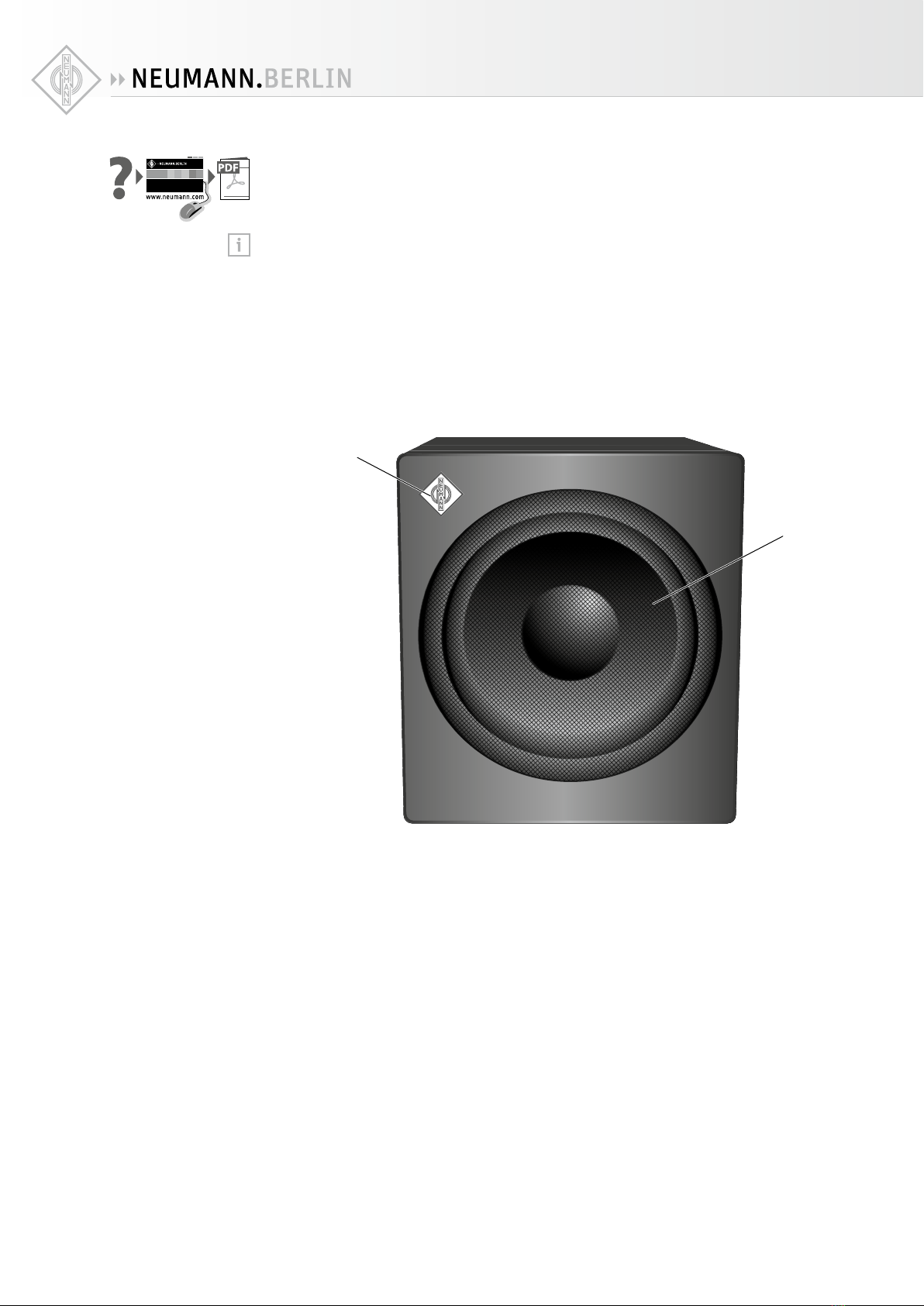
Product overview
1
2
1 Neumann logo
2 Metal grille

KH 750 DSP | 5
E
B
0
C
A
D
3
4
78 6 5
HIJ
F
G
9
3 MAINS POWER switch
4 IEC mains socket with protective ground contact
5 LOW CUT potentiometer
6 Redundant ETHERNET sockets
PRIMARY | AES67 AUDIO AND CONTROL NETWORK
SECONDARY | AES67 AUDIO
7 XLR3-M sockets
ANALOG OUTPUT | LEFT/A
ANALOG OUTPUT | RIGHT/B
8 XLR3-F sockets
ANALOG INPUT | LEFT/A
ANALOG INPUT | RIGHT/B
9 BNC sockets
DIGITAL | AES3 INPUT
DIGITAL | AES3 OUTPUT
0 INPUT GROUND LIFT switch
A SUBWOOFER GAIN | OUTPUT LEVEL switch
B SUBWOOFER GAIN | INPUT GAIN potentiometer
C SUBWOOFER PHASE switch
D SUBWOOFER PHASE switch
E BASS MANAGEMENT switch
F BASS MANAGEMENT LED
• green = active
G INPUT SELECT switch
H POWER ON LED
• green = on
• red = protection active
• amber = indication
I CONTROL MODE switch
J CHANNEL B INPUT MODE switch

KH 750 DSP | 6
Installing and connecting the KH 750 AES67
Have the product installed and connected by a specialist. Due to his/her technical training,
know-how and experience as well as knowledge of relevant provisions, regulations and stan-
dards, the specialist must be able to assess assigned tasks, recognize potential hazards and
ensure appropriate safety measures. The following safety and mounting instructions are
addressed to this specialist.
CAUTION
Danger of injury and material damage due to tipping/dropping of the product!
If improperly mounted, the product and/or the mounting hardware (e.g. rack) can tip over
or drop down.
X
Always have the product mounted by a qualified specialist according to local, national
and international regulations and standards.
X
Use the mounting systems recommended by Neumann and always provide sucient addi-
tional protection against tipping or dropping by means of safety wires.
CAUTION
Damage to the product due to overheating!
If air cannot circulate properly around the rear of the subwoofer, the power amplifiers may
overheat leading to premature activation of the thermal protection system which limits the
maximum output level of the subwoofer. In rare cases, damage to the product may also
occur.
XThe whole of the back panel should have a free flow of air to ensure good cooling.
XWhen installing the product into tight spaces such as wall recesses, maintain an air gap
of at least 2" (5 cm) around the subwoofer’s backplate to ensure a free air flow.
For information on installation, please refer to the supplied “Getting Started Quickly”
supplement. This will help you set up the subwoofers and loudspeakers in a way that
will give you the best acoustic performance from the system. For further information on
setting up subwoofers and loudspeakers, please refer to the “Questions & Answers” sec-
tion at www.neumann.com.
Preparing the subwoofer
CAUTION
Risk of staining surfaces!
Some surfaces treated with varnish, polish or synthetics may suer from stains when they
come into contact with other synthetics. Despite a thorough testing of the synthetics used
by us, we cannot rule out the possibility of staining.
XDo not place the KH 750 AES67 on delicate surfaces.
To place the subwoofer on a flat surface:
X
Attach the supplied self-adhesive feet to the bottom of the cabinet, about 2-3 cm (1") from
the edges.
This reduces the risk of scratching the surface and acoustically isolates the subwoofer from
the surface.
XAlternatively, the feet can be stuck onto the side of the cabinet if that helps with mounting
the product in the room.
If you want to hide the subwoofer:
XUse a thin open weave cloth. To provide visual cover, you can use two layers of the cloth.

KH 750 DSP | 7
Preparing the room
X
Arrange all acoustically relevant surfaces and objects symmetrically on either side of the
listening axis of the room (left/right).
XMinimize the sound that is reflected back to the listening position by using angled surfaces
and/or acoustical treatment.
X
The subwoofer can delivery very low frequencies at high levels which can lead to objects and
parts of the room structure to rattle. Ensure that rattling and resonating surfaces are avoided.
This product has been optimized for use in recording studios. In order to avoid aecting
the quality of reproduction, make sure that the product is used in an EMC environment.
Setting up the subwoofers
Choosing the type of setup
The driver is located on the front panel of the subwoofer, allowing the subwoofer to be either
set up in a room or flush mounted into a wall recess.
Flush mounting the subwoofer into a wall recess or placing it directly against the wall oers
the following advantages:
• A solid wall boosts the level of the subwoofer in the room which can be compensated by
reducing the output level of the subwoofer. This also reduces distortion resulting in a cleaner
sound reproduction.
• Reflections from the wall behind the subwoofer are eliminated so that the frequency
response becomes smoother.
• The subwoofer does not occupy space in the room when flush mounted.
If you want to flush mount the subwoofer into a wall recess:
X
Have the wall constructed by an experienced acoustical engineer. At least the following points
should be observed:
• The wall should be solid (stone, brick, concrete, several layers of gypsum or MDF).
• Ensure a free air flow around the rear of the subwoofer.
Using one or several subwoofers
XUse ...
one subwoofer several subwoofers
... if your room does not oer sucient
space for several subwoofers.
... if you require a higher output power
or less distortion with the same output
power.
... to suppress lateral modes or cross
modes in the room by means of a Plane
Wave Bass Array (PWBA™).
... if many smaller cabinets are easier to
position than one large cabinet.
To reduce low-frequency distortion, the uncalibrated output level of your subwoofer
should always be higher than the output level of your loudspeakers. We recommend
using arrays with several subwoofers, in which case the uncalibrated maximum output
level of the subwoofer array should also be higher than the maximum output level of all
the loudspeakers in the system. The subwoofers can then be calibrated to a lower output
level resulting in lower distortion and correspondingly cleaner low-frequency
reproduction.
For information on building a balanced system, please refer to the “Product Selection
Guide” at www.neumann.com.
If several subwoofers are used, they must be controlled parallelly by using Y cables
(analog inputs) to feed the signals to all subwoofers.
Alternatively, the same AES67 source stream can be routed to multiple subwoofers.
KH 750 DSP | 8
Positioning the subwoofers
Regardless of whether you are setting up one or several subwoofers:
X
Always ensure that the distance dwall between the wall behind the subwoofer and the sub-
woofer’s front is less than 0.8 m.
If you are setting up one subwoofer:
X
Position the subwoofer against the front wall, left or right of the middle of the front wall
ideally at 1/4 or 3/4 of the room width.
XDo not place the subwoofer at the side wall or rear wall of the room as sometimes proposed
for domestic applications.
If you are setting up several subwoofers as a Plane Wave Bass Array™(PWBA™):
XUse two to four subwoofers for smaller rooms and three to four subwoofers for larger rooms.
XSet up the subwoofers along the front wall within half a wavelength of the upper cut o fre-
quency of each other. The maximum spacing of the subwoofer cabinets is determined by the
setting of the routing mode or crossover frequency (see page 21):
Setting Max. spacing of the subwoofer cabinets
RIGHT approx. 2 m (6'6")
EXTERNAL BASS MANAGEMENT depends on crossover frequency setting in the
source equipment, for 80 Hz approx. 2 m (6'6")
LFE-MODE 1 approx. 1.4 m (4'6")
LFE-MODE 2 approx. 2 m (6'6")
If you observe the stated spacing, the subwoofers form a cylindrical source and generate
a plane wave down the room, a so-called Plane Wave Bass Array™(PWBA™). The PWBA™
reduces stationary waves between the side walls, improves the bass reproduction and
suppresses lateral room resonances.
You can correct excessive low frequency energy in the room using the potentiometer
SUBWOOFER GAIN| INPUT GAIN Band the switch SUBWOOFER GAIN | OUTPUT LEVEL A
(cf. page41).
If you set up several subwoofers, you can utilize their mutual coupling to achieve an acoustical
gain. The following acoustical gains are possible:
Number of subwoofers Acoustical gain
10.0 dB
26.0 dB
39.5 dB
412.0 dB
dwall
Utilizing the
acoustical gain

KH 750 DSP | 9
Positioning and orienting subwoofers and loudspeakers
Subwoofers are omni-directional in their typical pass band as the generated wavelength is
long compared to the surface producing the sound, therefore it does not matter in which direc-
tion the subwoofer is oriented when placed in the listening environment.
For your loudspeakers, however, an accurate positioning and orientation is vital.
XPosition your loudspeakers as follows:
System Position and orientation
2.0 (stereo) ±30°
5.1 ITU-R BS.775-1:
0°, ±30°, ±110° (±10°)
(center, front left/right, surround left/right)
ANSI/SMPTE 202M:
0°, ±22.5°, arrays to the surround left and to the surround right,
plus optional subwoofer(s)
6.1 as 5.1 systems plus 180° (back center)
7.1 0°, ±30°, ±90°, ±150°
(center, front left/right, side left/right, back left/right)
For detailed information on the positioning and orientation of your loudspeakers, please refer
to the operating manuals of the loudspeakers.
If your subwoofers cannot be placed at the same distance from the listening position as the
loudspeakers, time-of-flight dierences will occur.
XAvoid distance dierences of > 2m (6'6").
X
Compensate for time-of-flight dierences as described in the chapter “Calibrating the phase”
on page 19.
Connecting the subwoofer
Signal
(source connector) Source
impedance Cable length Subwoofer connection method
Analog (RCA) low up to 10 m
(30')
via an adapter (RCA-XLR)
to the ANALOG INPUT socket (XLR)
8 (see below)
Analog (XLR) low up to 100 m
(300')
directly to the ANALOG INPUT
socket (XLR) 8 (see below)
AES3 (BNC) 75 Ω up to 100 m
(300')
directly to the DIGITAL INPUT
socket (BNC)9 (see page 11)
AES3 (XLR) 110 Ω up to 100 m
(300')
via an impedance converter and an
adapter (XLR-BNC) to the DIGITAL
INPUT socket (BNC)9(see page
11)
S/P-DIF (RCA) 75 Ω up to 10 m
(30')
via an adapter (RCA-BNC) to the
DIGITAL INPUT socket (BNC)9 (see
page 11)
AES67 (RJ-45) 100Base-T;
1000Base-T
(recommen-
ded)
depending on
CAT type of
the cable
via Ethernet connectors (RJ-45)
The default signal selection is AES67. To select AES3 or analog, set the INPUT SELECT switch
to ANALOG and AES3. If a valid digital AES3 signal is connected to the BNC input, this digital
signal is automatically selected.
Note: The Neumann.Control iPad App does not support the KH 750 AES67 subwoofer.
Note: If the source equipment is digital, we recommend using digital connections from the
source to the subwoofer as this avoids additional unnecessary signal conversions.

KH 750 DSP | 10
Connecting analog signals to the KH 750 AES67
X
Use balanced XLR cables to connect the corresponding sockets ANALOG INPUT 8of the
KH 750 AES67 to the audio source.
XUse an XLR adapter (not supplied) to connect unbalanced cables (e.g. RCA cables).
Use the
following wiring if you want to make your own XLR adapter:
Wiring Pin Signal
Output (RCA) Input (XLR-M)
1Audio ground
2Signal +
3Signal -
The level delivered by devices with RCA outputs (-10 dBV) is usually less than the studio
level (+4 dBu):
X
If necessary, use active unbalanced-to-balanced converters in order to be able to connect
devices with unbalanced signals.
XWe do not recommend passive unbalanced to balanced converters using transformers. They
usually limit low frequency levels and increase high frequency distortion.
Connecting digital AES3 signals to the KH 750 AES67
X
Connect the digital AES3 or S/P-DIF-output signal of your audio source to the DIGITAL INPUT
socket 9of the respective KH 750 AES67. See picture below.
The KH 750 AES67 subwoofer only supports non-encoded AES3 and S/P-DIF sig-
nals. Encoded signals such as MP3, DTS or Dolby Digital are not supported.
Only one cable is needed for uncompressed AES3 and S/P-DIF digital signals
(single-wire mode). They contain two audio channels: “subframe A” and “sub-
frame B”. Usually, the audio channels are:
Subframe A Subframe B
Left Right
Center LFE
Surround left Surround right
Back left Back right
A clock input is not required because subwoofers are not audio sources and the
converters are clocked to a very stable internally generated clock source.
X
Use a Neutrik NADITBNC-F impedance and level converter (not supplied) for XLR to BNC
conversions of AES3-signals. This method brings impedance matching, level matching and
source-receiver isolation. The Neutrik NADITBNC-F converter is guaranteed to work up to
48kHz. Only one converter is needed per digital signal cable.
XUse the following wiring if you want to make your own converter:
CAUTION
Damage to the product due to high AES3 signal levels!
AES3 signal levels in XLR cables are much too high for the DIGITAL INPUT socket
(BNC)9. If you connect such signals without reducing the signals’ level, damage to the
product will occur.
XAlways make sure that your converter is able to match impedance and level.
Connecting
unbalanced
cables
Connecting
AES3 cables

KH 750 DSP | 11
Wiring Pin Signal
110
cable
AES3 on XLR to AES3 on BNC Connections
75
cable
110
57 mW
54.9
112 mW
187
26 mW
56.2
1.2 mW
Use E96 1% resistors
Source
(XLR-F)
Subwoofer
(BNC)
1Shield
2Signal +
3Signal -
This method brings impedance matching and level matching, but no source-receiver isolation.
Use a resistor network to passively attenuate the XLR signal from 3.1 V down to 0.42V and
change the impedance from 110 to 75 .
Connecting digital AES67 signals to the KH 750 AES67
In order to use the AES67 digital audio network stream, please observe the chapter “Configur-
ing AES67 network and audio settings” on page 23, which provides detailed information on
the entire AES67 configuration and usage.
Connecting loudspeakers to the subwoofer
For a simplified representation, the following connection examples show loudspeakers in com-
bination with the KH 750 AES67 subwoofer. Each of the examples only shows one possible
combination of loudspeakers and subwoofers. For information on building a balanced system,
please refer to the “Product Selection Guide” at www.neumann.com.
Either use balanced XLR cables to connect the corresponding ANALOG OUTPUT 8sockets of
the subwoofer to the analog input sockets of the loudspeakers or use the DIGITAL OUTPUT 9
socket for loudspeakers with digital inputs.
When using the MA 1 - Automatic Monitor Alignment software the digital inputs of the
Neumann studio monitors (KH 120 D, KH 310 D, KH 420 with DIM 1 module) are not sup-
ported. For these models, use the analog inputs instead.
Connecting
AES67 audio
network cables
KH 750 DSP | 12
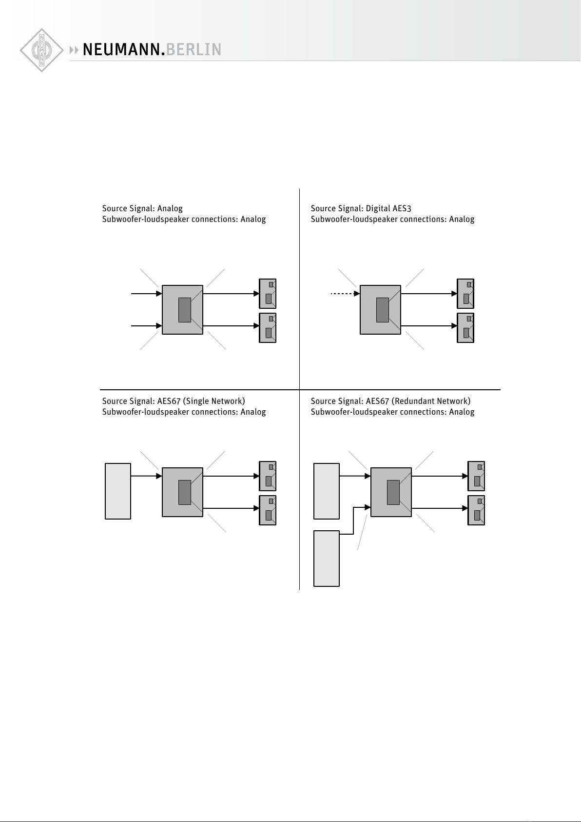
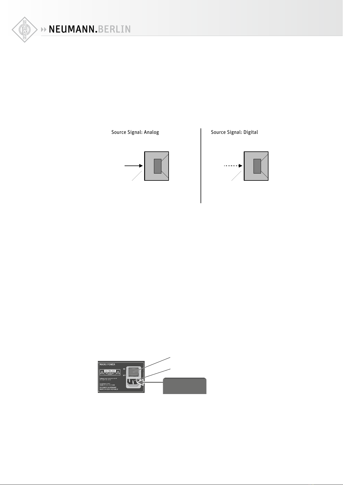
Full range stereo (bass managed): two loudspeakers and one subwoofer
XFind the correct cabling diagram below depending on your source signal type (analog or
digital).
XSet the CHANNEL B INPUT MODE switch Jto STEREO.
Source Signal: Analog
Subwoofer-loudspeaker connections: Analog
Source Signal: Digital AES3
Subwoofer-loudspeaker connections: Analog
Source Signal: AES67 (Single Network)
Subwoofer-loudspeaker connections: Analog
Source Signal: AES67 (Redundant Network)
Subwoofer-loudspeaker connections: Analog
L
Sub
ANALOG INPUT LEFT/A
ANALOG INPUT RIGHT/B ANALOG OUTPUT RIGHT/B
ANALOG IN
ANALOG IN
ANALOG IN
ANALOG IN
R
L/R
Sub
ANALOG OUTPUT LEFT/AANALOG OUTPUT LEFT/A
ANALOG OUTPUT RIGHT/B
8 7
78
Sub
AES 67 PRIMARY
(Stereo Stream L/R)
ANALOG OUTPUT RIGHT/B
ANALOG IN
ANALOG IN
ANALOG OUTPUT LEFT/A
6
7
7
DIGITAL AES3 INPUT 9 7
7
PRIMARY
Network Switch
Sub
AES 67 PRIMARY
(Stereo Stream L/R)
ANALOG OUTPUT RIGHT/B
ANALOG IN
ANALOG IN
ANALOG OUTPUT LEFT/A
6
AES 67 SECONDARY
(Stereo Stream L/R)
6
7
7
PRIMARY
Network Switch
SECONDARY
Network Switch
Stereo systems
KH 750 DSP | 13
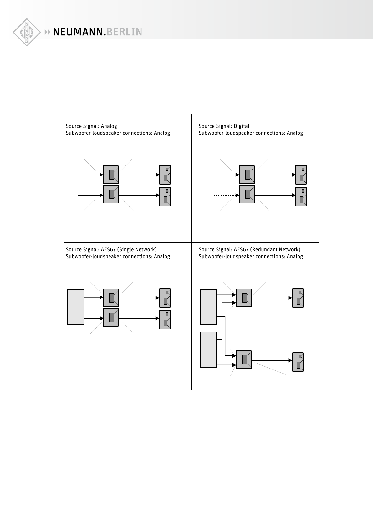
Full range stereo (bass extension): two loudspeakers and two subwoofers
XFind the correct cabling diagram below depending on your source signal type (analog or
digital).
XSet the CHANNEL B INPUT MODE switch Jto STEREO.
Source Signal: Analog
Subwoofer-loudspeaker connections: Analog
Source Signal: Digital
Subwoofer-loudspeaker connections: Analog
Source Signal: Analog
Subwoofer-loudspeaker connections: Digital
Source Signal: Digital
Subwoofer-loudspeaker connections: Digital
Sub L
Sub R
ANALOG INPUT LEFT/A
ANALOG INPUT RIGHT/B ANALOG OUTPUT RIGHT/B
ANALOG IN
ANALOG IN
Sub L
Sub R
ANALOG IN
ANALOG IN
L
R
ANALOG OUTPUT LEFT/A
Sub L
Sub R
DIGITAL AES3 INPUT
DIGITAL AES3 INPUT ANALOG OUTPUT RIGHT/B
ANALOG IN
ANALOG IN
L
R
ANALOG OUTPUT LEFT/A
8
8
7
7
ANALOG OUTPUT RIGHT/B 7
ANALOG OUTPUT
RIGHT/B 7
7
7
9
9
Source Signal: AES67 (Single Network)
Subwoofer-loudspeaker connections: Analog
Source Signal: AES67 (Redundant Network)
Subwoofer-loudspeaker connections: Analog
ANALOG OUTPUT LEFT/A
AES 67 PRIMARY
(Stereo Stream L/R)
6
AES 67 PRIMARY
(Stereo Stream L/R)
6AES 67 PRIMARY
(Stereo Stream L/R)
6
AES 67 PRIMARY
(Stereo Stream L/R)
6
7
PRIMARY
Network Switch
Sub L
Sub R
ANALOG IN
ANALOG IN
ANALOG OUTPUT LEFT/A
AES 67 SECONDARY
(Stereo Stream L/R)
6
AES 67 SECONDARY
(Stereo Stream L/R)
6
7
PRIMARY
Network Switch
SECONDARY
Network Switch

KH 750 DSP | 14
Discrete multichannel systems (professional applications)
In multichannel systems, stereo pairs of loudspeakers (L/R, Ls/Rs, etc.) can be connected to
subwoofers as shown above. For all further channels proceed as follows (not supported by
the Neumann.Control iPad App).
X
For the Center and Sub/LFE channels, find the correct cabling diagram below depending
on your source signal type (analog or digital).
XThe Center channel must be connected to the analog A input or be located on the digital
A channel. The Sub/LFE channel must be connected to the analog B input or be located on
the digital B channel.
X
Depending on how you wish to handle the Sub/LFE channel, set the CHANNEL B INPUT
MODE switch Jto EXTERNAL BASS MANAGEMENT, LFE-MODE 1 or LFE-MODE 2.
• EXTERNAL BASS MANAGEMENT replays the “Sub” channel full range through the sub-
woofer (preferred setting for already encoded signals or a mixing console with bass
management enabled). In the source equipment, set the loudspeakers to “Small” and
the crossover frequency to 80 Hz.
• LFE-MODE 1 replays the LFE channel up to 120 Hz through the subwoofer (preferred set-
ting for movie mixes, pre-encoded mixes).
• LFE-MODE 2 replays the LFE channel up to 80 Hz through the subwoofer and above 80
Hz through the connected center loudspeaker, thereby giving full range monitoring for
the LFE channel (preferred setting for music mixes).
Source Signal: Analog
Subwoofer-loudspeaker connections: Analog
Source Signal: Digital
Subwoofer-loudspeaker connections: Analog
Source Signal: Analog
Subwoofer-loudspeaker connections: Digital
Source Signal: Digital
Subwoofer-loudspeaker connections: Digital
Note: Set the center loudspeaker input signal
select to Digital A
Note: Set the center loudspeaker input signal
select to Digital A
C
Sub
ANALOG INPUT LEFT/A
ANALOG INPUT RIGHT/B
ANALOG INPUT LEFT/A
ANALOG INPUT RIGHT/B
ANALOG IN ANALOG IN
Sub/LFE
C
Sub
DIGITAL IN DIGITAL IN
Sub/LFE
C
Sub/LFE
Sub
DIGITAL AES67 INPUT ANALOG OUTPUT LEFT/A
ANALOG OUTPUT LEFT/A
DIGITAL AES3 OUTPUT
DIGITAL AES3 OUTPUT
C
Sub/LFE
DIGITAL AES3 INPUT
Sub
8 7 76
DIGITAL AES3 INPUT 9
00
8
9 0
9
Multichannel
systems
KH 750 DSP | 15
Bass managed multichannel systems (domestic applications)
XIn multichannel systems where there is a bass manager preceding the monitoring system
(for example in surround sound processors), connect the loudspeakers and subwoofer(s)
directly to the source equipment (analog or digital). The “Sub” signal should be connected
to the analog B input or be located on the digital B channel.
XSet the CHANNEL B INPUT MODE switch Jto EXTERNAL BASS MANAGEMENT.
X
In the surround sound processor, set the loudspeakers to “Small” and the crossover fre-
quency to 80 Hz.
Source Signal: Analog
Source Signal: Digital
Sub
Sub
ANALOG INPUT
RIGHT/B
Sub
Sub
DIGITAL AES3
INPUT (B channel)
DIGITAL AES67 INPUT
8 9
6
Connecting network cables
To use the extended functionality oered by MA 1 - Automatic Monitor Alignment software,
the subwoofer must be connected via the PRIMARY ETHERNET socket to a standard network
switch using a user supplied standard Ethernet cable (Cat 5 or better). The maximum length of
the cable is 100 m.
The software wizard will guide you through the network setup procedure.
Connecting/disconnecting the subwoofer to/from the
mains power supply
To connect the KH 750 AES67 to the mains power supply:
XMake sure that the switch MAINS POWER 3is set to “OFF”.
XConnect the IEC connector of the supplied mains cable to the IEC mains socket 4.
Power Source
3
4
XConnect the mains plug of the mains cable to a suitable wall socket.
To disconnect the KH 750 AES67 from the mains power supply:
XSet the switch MAINS POWER 3to “OFF”.
XPull the mains plug out of the wall socket.
KH 750 DSP | 16
Configuring and using the KH 750 AES67
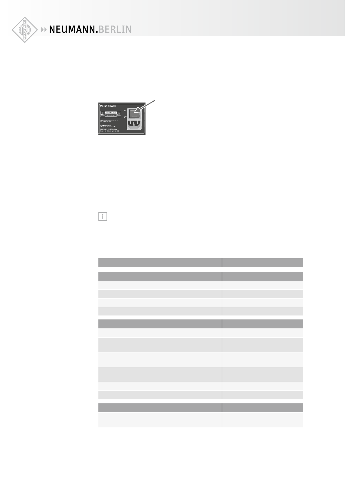
Switching the subwoofer on/o
You can switch the KH 750 AES67 on and o using the switch MAINS POWER 3.
XSet the switch MAINS POWER 3 to:
• “ON” to switch the subwoofer on.
If the INPUT SELECT switch Gis set to ANALOG and AES3: The POWER ON LEDHlights
up red for 5 seconds, during which the subwoofer is muted. The POWER ON LEDHthen
lights up green.
If the INPUT SELECT switch Gis set to AES67: The POWER ON LEDHlights up red for 5
seconds and then solid amber for 2 minutes, during which the subwoofer is muted. The
POWER ON LEDHthen lights up green.
• “OFF” to switch the subwoofer o. The POWER ON LEDHlights up red and goes o after
a few seconds. The subwoofer mutes immediately when it is switched o.
There is a five second delay (analog or AES3 input) before sound can be heard from the
KH 750 AES67 and the loudspeakers connected to the outputs in order to avoid noises
(pops) from preceding equipment switched on at the same time. Conversely, switching
o the subwoofer immediately mutes the audio.
Functionality of the back panel lights
Action Indication
Firmware activities
Subwoofer is booting up Power LED solid red
Subwoofer boot up error Power LED flashing red
Subwoofer firmware is being updated Power LED solid amber
Subwoofer resetting to factory default settings Power LED flashing red
Everyday operation
Operating normally Power LED solid green
Subwoofer in active system is solo’ed in the
Neumann.Control iPad App
Power LED solid green
Subwoofer system output level is muted
(GUI button on Operate page)
Power LED solid red
Subwoofer system output level is dimmed
(GUI button on Operate page)
Power LED solid green
Bass management disabled Bass management LED o
Bass management active Bass management LED green
Protection
Protection system is activated (takes priority over
other indications)
Power LED red
On/o switching
using the switch
MAINS POWER 3

KH 750 DSP | 17
INPUT SELECT switch
If the INPUT SELECT switch Ghas been set to ANALOG and AES3, only the XLR and BNC inputs
are active. The KH 750 AES67 will switch to standby after 90 minutes without an input signal.
The priority is on the digital BNC input.
Standby means that the network interface, signal processing circuitry and power amplifiers
are all powered down. Standby mode is automatically deactivated when a suciently large
audio signal is detected at the input. The time taken to resume normal operation and hear
sound is 5 seconds.
If the INPUT SELECT switch G has been set to AES67, only the AES67 inputs are active. Auto
standby is disabled in order to guarantee continuous network discovery, even without an
active audio signal.
CONTROL MODE switch
If the CONTROL MODE switch Ihas been set to LOCAL, the KH 750 AES67 will not react to
network commands from the MA 1 - Automatic Alignment software. Control of the subwoofer
will be from the backplate only.
If the CONTROL MODE switch I has been set to NETWORK, the KH 750 AES67 will react to net-
work commands from the MA 1 - Automatic Alignment software. All backplate controls marked
with “*” will be ignored.
If the CONTROL MODE switch I is set to NETWORK but there is no network connection and
active MA 1 - Automatic Alignment software, the last used network configuration will be used.
If the MA 1 - Automatic Alignment software has not been connected before, the default settings
will be used.
If you have configured any settings via the MA 1 - Automatic Alignment software and you
remove the network cable, the current settings will stay active.
By switching from network control to local control you can easily switch between a configu-
ration set using the MA 1 - Automatic Alignment software and settings made directly on the
subwoofer.
This can make sense if you want to temporarily use the subwoofer in a dierent location than
your measured studio environment.
The subwoofer does not lose its settings even when disconnecting it from the network or the
mains supply.
Resetting the KH 750 AES67
To reset the KH 750 AES67 internal controls to their factory default values:
XSwitch on the KH 750 AES67.
XWhile the power light is solid red during the boot up phase, move the INPUT SELECT switch
Gup and down repeatedly until the power light turns to green for a few seconds.
The power light will then flash red while the default settings are being applied before revert-
ing to green.
Firmware update
Firmware updates are done via the MA 1 - Automatic Alignment software. When it is opened
it surveys the network for subwoofers and checks if the firmware is up to date. If a firmware
update is needed, you will be prompted to follow the on-screen instructions. It takes approxi-
mately 12 to 15 minutes per subwoofer to do the update.

KH 750 DSP | 18
Calibrating the subwoofer
Before using your system for the first time and whenever you change the physical conditions in
your listening environment, carry out the following steps:
XAdjust the frequency response and the level of the loudspeakers before calibrating the sub-
woofer (see the operating manual of the loudspeakers):
Application Recommended frequency response Comments
Studio flat A flat response brings good
translation
Film X-curve shape ANSI/SMPTE 202M:
the shape of the X-curve
depends on the size of the room
Home subjective evaluation Not necessarily a flat response,
a gently downward sloping
response with increasing
frequency is often preferred
All the loudspeakers in the system should have the same level at the listening position. This
is often measured using a pink noise test signal that is set to -18 dBFS (Europe) or -20 dBFS
(USA) on the mixing console’s output level meters and a sound level meter set to “C-weighted”
and “slow”.
XCalibrate the frequency response, the phase and the acoustical level of the subwoofer.
To do so, choose one of the following methods:
Alignment using the MA 1 - Automatic Alignment software:
It is highly recommended to use the MA 1 - Automatic Alignment software to calibrate the
loudspeakers and subwoofer in the room. Follow the instructions during the alignment pro-
cess. Observe the following requirements:
Hardware:
• KH 750 AES67 subwoofer in combination with a pair of KH DSP loudspeakers or a pair of
analog KH loudspeakers
• Neumann MA 1 measurement microphone
• Computer (screen resolution of 1280x720 or higher)
• Audio interface with balanced analog input with 48 V phantom power and two balanced
analog outputs
• Network switch
Software:
• Operating system: Windows 10 (64 bit) or macOS 10.13, 10.14 or 10.15
• ASIO driver (for Windows)
• MA 1 - Automatic Monitor Alignment software
Calibration using the backplate controls:
A: Calibration using an acoustical measurement system
Calibrating the frequency response, phase and sound pressure level by means of an acoustical
measurement system should always be your first choice since it yields the highest accuracy.
This method is described below.
B: Calibration using Neumann test signals
In the absence of an acoustical measurement system, you can calibrate the settings of your
subwoofer using Neumann test signals (see page 20).
C: Calibration using music signals and an 80 Hz test signal
A calibration by means of music signals is also possible but should always be the last choice.
In this case, play an 80 Hz test signal from your source equipment to calibrate the phase
(see page 20).

KH 750 DSP | 19
Calibration using the backplate controls and an acoustical measurement system
The settings of the switch SUBWOOFER GAIN | OUTPUT LEVEL Aand the potentiometer
SUBWOOFER GAIN | INPUT GAIN Brecommended in the following table are valid for
the following settings of your Neumann loudspeaker: INPUT GAIN: “0 dB” and OUTPUT
LEVEL: “100 dB SPL at 1m for 0 dBu”. For information on how to set your Neumann
loudspeaker, please refer to its operating manual. If the mentioned values cannot be set
on your loudspeaker, adjust the subwoofer accordingly.
The frequency response of a subwoofer depends on its position in the room and on the room
geometry. The same subwoofer installed in dierent positions in the same room may require
dierent acoustical control settings.
XAdjust the frequency response of the subwoofer at your listening position. To do so, proceed
as follows:
X
Make sure that the switch SUBWOOFER GAIN | OUTPUT LEVEL Ais set to “100 dB SPL at 1m
for 0 dBu”.
X
First, set the potentiometers SUBWOOFER GAIN | INPUT GAIN Band LOW CUT 5to the
following settings. These settings can be used as a starting point for further adjustment:
Subwoofer position Setting of potentiometer
SUBWOOFER GAIN | INPUT GAIN B
Setting of potentiometer
LOW CUT 5
In a corner -8 dB 0 dB
Next to or flush
mounted in an
acoustically solid
wall (e.g. brick,
concrete)
-4 dB 0 dB
Next to or flush
mounted in an
acoustically soft
wall (e.g. gypsum)
-2 dB 0 dB
Free standing in an
untreated room
-2 dB 0 dB
Free standing in a
well-treated room
0 dB 0 dB
XCheck the frequency response at the listening position using your acoustical measurement
system:
• In the case of excessive very low frequency levels at the listening position, turn the
potentiometer LOW CUT 5 to the left. This reduces the output level of the subwoofer
towards lower frequencies.
XMeasure the subwoofer’s sound pressure level at the listening position.
XAdjust the sound pressure level of the subwoofer so that the level of the frequency response
of the subwoofer below 80 Hz corresponds to the level of the frequency response of the
loudspeakers above 80 Hz.
• To do so, use the potentiometer SUBWOOFER GAIN | INPUT GAIN Band the switch
SUBWOOFER GAIN | OUTPUT LEVEL A. Make sure that the input signal is not too high.
XSet the phase using the left switch SUBWOOFER PHASE D. Values from -180ºto -315º can
be obtained by setting the right switch SUBWOOFER PHASE Cto “–180º” and by adding the
set value of the left switch SUBWOOFER PHASE D.
Example: To obtain a phase shift of –270º, set the right switch SUBWOOFER PHASE Cto
“–180º” and the left switch SUBWOOFER PHASE Dto “–90º”.
XSet the left switch SUBWOOFER PHASE Din combination with the right switch SUBWOOFER
PHASE Cto values of 0º, -45º, -90º, -135º, -180º, -225º, -270º, and -315º, until you have
found the setting that gives the lowest sound pressure level at the listening position at the
cut-o frequency of 80 Hz (180º phase shift between subwoofer and loudspeaker, maximum
level cancelation).
Calibrating the
frequency
response
Calibrating the
subwoofer level
Calibrating the
phase

KH 750 DSP | 20
X
Set the right switch SUBWOOFER PHASE Cto the opposite position. The phase shift between
loudspeaker and subwoofer is now 0º. Check your subwoofer’s sound pressure level again
and, if necessary, readjust it so that it corresponds to the sound pressure level of the
loudspeakers.
Your system is now completely acoustically calibrated.
Note that any change of the low cut influences the crossover phase. Therefore, the
phase and the level need to be recalibrated after changing the low cut EQ setting.
Calibration using the backplate controls and Neumann test signals
XDownload the Neumann test signals and the instructions for use (PDF file, in English) from
the KH 750 AES67 product page at www.neumann.com.
XFollow the steps described there.
Calibration using the backplate controls, music signals and an 80 Hz test signal
X
Adjust the settings for the sound pressure level and the frequency response as described
above.
X
Calibrate the acoustical phase using an 80 Hz test signal. Check the settings of the sound
pressure level and frequency response by means of music signals you are familiar with.
• Connect the left front loudspeaker to the socket OUTPUT | LEFT 8.
• Set the switch BASS MANAGEMENT Eto “ACTIVE”.
• Play an 80 Hz test tone from your source into the audio input INPUT | LEFT 9so that the
subwoofer and left loudspeaker are playing the tone.
• Set the left switch SUBWOOFER PHASE Din combination with the right switch SUB-
WOOFER PHASE Cto values of 0º, -45º, -90º, -135º, -180º, -225º, -270º, and -315º,
until you have found the setting that gives the lowest sound pressure level at the listening
position at the cut-o frequency of 80 Hz (180ºphase shift between subwoofer and loud-
speaker, maximum level cancelation).
• Switch o the test signal at the source.
• Set the right switch SUBWOOFER PHASE Cto the opposite position.
The phase shift between loudspeaker and subwoofer is now 0º.
X
Check the settings of the sound pressure level and frequency response by means of music
signals. Listen for a smooth extension of the frequency response of the main loudspeakers
down to 20 Hz.
To do this, proceed as follows:
X
Listen to music containing content down to 20 Hz. Activate and disable the bass management
by repeatedly moving the switch BASS MANAGEMENTEbetween the two positions. There
should be no increase or decrease in level between the lower cut o frequency of the loud-
speaker and 80 Hz.
Compensating for larger time of flight (TOF) dierences
If the subwoofer is placed at a distance > 2 m (6'6") behind the loudspeakers with reference to
the listening position, the subwoofer back panel phase controls will not suce. In this case
use the MA 1 - Automatic Monitor Alignment software to align the loudspeakers automatically.
This method provides the highest possible flexibility in terms of higher distance dierence.
Using the bass management
X
For a two-channel stereo system set the switch CHANNEL B INPUT MODE Jto “STEREO/
RIGHT”.
XSet the switch BASS MANAGEMENT Eto “ACTIVE”.
The bass management is activated. This inserts a 4
th
order 80 Hz high pass filter into the
signal path of the audio outputs OUTPUT | LEFT and RIGHT 8and routes all audio signals
below 80 Hz to the subwoofer. The LED BASS MANAGEMENT Flights up green.
If you deactivate the bass management, the audio signal of the audio outputs OUTPUT | LEFT
and RIGHT 8is only reproduced by the loudspeakers. Use this function to prevent the low
frequency signal components of the main channels being reproduced by the subwoofer.
XSet the switch BASS MANAGEMENT Eto “DISABLED”.
This manual suits for next models
1
Table of contents
Other Neumann Subwoofer manuals


