Neurona AX821 User manual

1
20130512 V1.

2
Table of Content
1.IMPORTANT INFORMATION...........................................................................................1
1.1. IMPORTANT SAFETY NOTES...........................................................................................1
2.INTRODUCTION...............................................................................................................2
2.1. PACKAGE CONTENT......................................................................................................2
2.2. PRODUCT OVERVIEW....................................................................................................3
2.3. BUTTONS AND LEDS....................................................................................................4
3.HARDWARE INSTALLATION ..........................................................................................5
3.1. APPLICATION 1–ESTABLISH HY-FI NETWORK................................................................5
3.2. APPLICATION 2–EXPAND WI-FI NETWORK ....................................................................6
4.ENCRYPTED PLC NETWORK.........................................................................................6
4.1. CREATE AN ENCRYPTED PLC NETWORK GROUP ............................................................6
4.2. REMOVE DEVICE FROM AN EXISTING NETWORK GROUP ..................................................7
4.3. CREATE ADDITIONAL ENCRYPTED NETWORK..................................................................8
5.ADVANCED WI-FI SETTINGS VIA WEB BROWSER......................................................9
5.1. GETTING STARTED .......................................................................................................9
5.2. LOGIN TO SETTING PAGE ............................................................................................11
5.3. HOME........................................................................................................................12
5.4. HY-FI NETWORKING SETTINGS ....................................................................................15
5.5. INTERNET SETTINGS ...................................................................................................20
5.6. WIRELESS SETTINGS ..................................................................................................21
5.7. ADMINISTRATION ........................................................................................................30
5.8. CHANNEL NUMBER.....................................................................................................33
6.ENHANCE PLC PERFORMANCE .................................................................................35
7.SPECIFICATIONS ..........................................................................................................37

1
1.Important Information
Important Safety Notes
The Device is intended for connection to the AC power line. For installation instructions,
refer to the Installation section. The following precautions should be taken when using this
product.
zPlease read all instructions before installing and operating this product.
zPlease keep all instructions for later reference.
zPlease follow all warnings and instructions marked on the product.
zFor safety reason, when device is being powered on, this product should NOT be
installed in any electric socket which makes the surface with venting holes on
the product to face downward (facing the floor).
zUnplug the Powerline device from the wall outlet before cleaning. Use a dry cloth
for cleaning. DO NOT use liquid cleaners or aerosol cleaners.
zDO NOT operates this product near water.
zThis product should never be placed near or over a radiator, or heat register.
zThis product relies on the building’s electrical installation for short-circuit (over current)
protection.
zDO NOT allow anything to rest on the product interconnect plug. DO NOT locates this
product where people may walk on the cords.
zBecause this product sends data over the power line, it is recommended that you plug
directly into a power outlet. Do not plug the Device into a UPS or power strip with surge
protection. The product has its own power filter for protection against surges.
zOnly a qualified technician should service this product. Opening or removing covers
may result in exposure to dangerous voltage points or other risks.
zUnplug the product from the wall outlet and refer the product to qualified service
personnel for the following conditions:
¾When the interconnect cords are damaged or frayed.
¾If liquid has been spilled into the product.
¾If the product has been exposed to rain or water.
¾If the product does not operate normally when the operating instructions are
followed.
¾If the product exhibits a distinct change in performance.

2
2. Introduction
The Hy-Fi HD Booster is a wireless device with Powerlione Communication (PLC)
technology integrated. It takes advantage of wireless and powerline connections for
providing more flexible and reliable bandwidth. That means it transmits at powerline or
wireless interface, no matter which one your device use, they will automatically connect to
the best available interface for the fast performance.
With Hy-Fi technology comes the intelligent “Path Switch”, it can re-assign traffic to the other
connection if it experiences connection congested, without the user noticing the change has
ever occurred.
This product is suitable for general users to operate in their homes/houses, while advanced
configurations through web-browser described in later chapters are suitable for seasoned
users to change and manage the Hy-Fi HD Booster product settings.
Package Content
Before starting the installation of the device, please make sure the package contains the
following items:
Single pack Dual pack
Device
错误!链接无效。 错误!链接无效。
Accessories ¾RJ-45 Cable x 1
¾QIG x 1
¾RJ-45 Cable x 2
¾QIG x 1
Hy-Fi HD Booster Hy-Fi HD Booster
Hy-Fi HD Booster

3
Product Overview
800Mbps Hy-Fi HD Booster

4
Buttons and LEDs
LED
ON: Power on and ready.
Blinking: PLC group pairing.
OFF: Power off.
ON: PLC connection detected.
Blinking:
1. Fast:
Powerline data rate > 60Mbps
2. Normal:
60Mbps > Powerline data rate > 10Mbps
3. Slow:
10Mbps > Powerline data rate
OFF: No PLC connection detected.
(They are too far to communicate or it is alone in its logical network).
Steady Green: Wi-Fi network with security protection.
Flash Green: Wi-Fi network traffic in transaction with security protection.
Steady Red: Wi-Fi network without security protection.
Flash Red: Wi-Fi network traffic in transaction without security protection.
Blinking Green (0.5 sec ON / 0.5 sec OFF): WPS negotiation.
OFF:Wi-Fi disabled.
ON: Ethernet connection detected.
Blinking: Network traffic in transaction.
OFF: No Ethernet connection detected.
Buttons
Power Button Push to power on/off the device.
AP Clone by default. The function follows Operation Mode setting in WPS
configuration.
Press 10 seconds:
Randomly generate a new PLC network group name.
Press 1 to 3 seconds:
Start paring with the other PLC device. Paring procedure keeps for 2 minutes or
ends automatically when they are paired. It can be stopped manually by pressing
the button for 1 to 3 seconds again.
Reset Button Press 1 second: Reset to factory default setting.
Press the button when the device is powered (not in standby mode)

5
3.Hardware Installation
Application 1 – Establish Hy-Fi Network
The Hy-Fi HD Booster takes advantage of wireless and powerline connections for providing
stable and reliable home networking.
To establish Hy-Fi network, user needs at least 2 Hy-Fi HD Boosters. Once Hy-Fi HD
Booster connects with a router, it will automatically turn into Hy-Fi router. Hy-Fi router will
automatically detect and configure other Hy-Fi HD Boosters plugged in around the home on
the network.

6
Application 2 – Expand Wi-Fi Network
To extend wireless AP coverage in different room or floor, user can place the Hy-Fi HD
Boosters near the mobile devices such as iPad, Tablet, Smartphone and Notebook. The
Hy-Fi HD Booster will turn itself into Hy-Fi extender. User can deploy multiple Hy-Fi
extenders, using a single network name for all devices to eliminate the need to switch from
one to one while moving around the house.
Once your Hy-Fi extenders are connected, any change to the wireless configuration of Hy-Fi
router will automatically be applied to connected Hy-Fi extenders.
4.Encrypted PLC Network
Create an Encrypted PLC Network Group
The Powerline bridges are compliant with HomePlug AV specification. Every ‘HomePlug AV’
compliant PLC device that has the same default network name, “HomePlug AV”, is capable
of communicating with other “HomePlug AV” devices. This is the so called “Public
Network”. Two or more powerline devices under the same network can communicate with
one another.
If you have a pair of powerline device, either one in the pair can be “device A” or “device B”.
By pressing the GROUP button more than 10 seconds; it will generate a random network
group (different from HomePlug AV). Users can take the following two steps to change the
public network group to the private network group to protect their data while transmitting
over the powerline. Users also can create more than one private network groups by
pressing GROUP button directly without software installation required.

7
*NOTE: Put the Devices side by side will be more convenient during the setting procedure.After network group
is set, the Devices can be deployed anywhere at home.
Step I: Clear Group Attribute
Clear the original network group of device B by pressing its GROUP button more than 10
seconds until all LED lights simultaneously turns off and on once. At this moment, its
network group name has been changed to a random name. It means that this device is (1)
ready to be assigned another network name or (2) to be used as a seed device so
other PLC devices can join to a private network group.
Step II: Join to Other Network Group
1. Press GROUP button of device A for 2 to 3 seconds (make sure POWER LED starts
blinking).
2. Press GROUP button of device B for 2 to 3 seconds (make sure POWER LED starts
blinking).
The Device B which has cleared its group attribute will join to the Device A which has not.
This step makes device Aand B are under the same encrypted network. Additional device C
can be added into device A’s logical network by taking same steps, thus all of the Device A,
B, and C in the same encrypted network group. User can assign as many powerline devices
into the logical network group as described in the SPECIFICATION section.
*NOTE: It does not matter which device’s button is pressed first, but please press the second device’s
GROUP button within two minutes after pressing first device’s GROUP button. After 10 seconds, device will
start communicating with deviceA.
Remove Device from an Existing Network Group
If you would like to remove powerline device from an existing network group, you can
generate a new group name (referring to Step I) to stop communication with an existing
network group.

8
Create Additional Encrypted Network
If you want to create additional private network for your powerline devices that co-existence
with your existing powerline private network group, please repeat the Step 1 & 2 to generate
new private network group for selected powerline devices.
P.S. Users can press the RESET button to reset the network name back to its factory default.

9
Default username: root
Default password: root
5.Advanced Wi-Fi Settings via WEB Browser
Getting Started
To set up advanced Wi-Fi features such as SSID
or password, please connect to Hy-Fi HD Booster
via Ethernet or wireless connection, and login to
the setting page through web browser.
Before logging in to the setting page, PC or mobile device
should be in the same subnet as this device. To do so,
please manually change PC or mobile's IP address.
Go to "Network Connections" - "Local Area
Connection" "Connection Status" and choose the
Internet Protocol (TCP/IP) and click on
"Properties".
Enter IP address such as 192.168.1.XXX
(XXX can be set from 1-128) and click OK
10
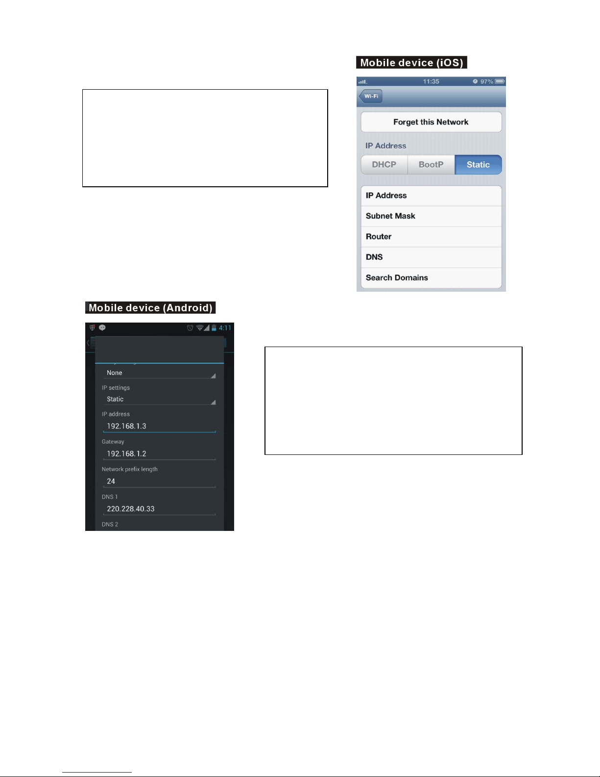
Go to "Settings" - "Wi-Fi" - "Selected SSID" -
"Advanced settings", then click on "Static"
to enter IP address such as 192.168.1.XXX.
(XXX can be set from 1-128) and Subnet Mask
255.255.255.0
Go to "Settings" - "Wi-Fi" - press & hold
"Selected SSID" to modify network - then
click on "Show advanced options".
Click "IP settings" to choose "Static" to enter
address such as 192.168.1.XXX.
(XXX can be set from 1-128)

11
Log in to the Setting Page
Step 1 Step2
Open the Web browser and type in
IP address 192.168.1.2
(the IP of this device).
Step 3
The Hy-Fi HD Booster setting page will be
displayed after successful login and you can
start configuring all necessary settings from
here.
Note: After completing all necessary configurations, DO NOT forget to change the
PC or mobile device's IP address back to your original setting.
When see the login window enter "root"
in both user name and password fields.
Note: you can change user name and
password in Administration tab.

12
Home
Configuration details for Home section are explained as the following.
Select Language
Currently English is only the available option in the language setting.
Setup Wizard
The setup Wizard helps you to set up the device with minimum required settings. On the
left panel click ‘SETUP WIZARD’ and then click the “Next” button. The wizard will guide you
through required setting.
Step 1:Set up account and password configuration for device login.
Step 2:Set up LAN interface.
Step 3:The page is for basic wireless setting to set network mode, SSID, etc.
Step 4:Set up wireless security and encryption to prevent from unauthorized access.
Step 5:Click “Finish” button and the device will reboot to apply the changes.

13
Operation Mode
This device supports five operation modes for the IP network. Click to select one from the
following options and then click Apply button.
AP Mode
The device acts as WirelessAccess Point (AP) for wireless clients and provides
connections to Ethernet and PLC.
Client Mode
This mode enables the establishment of connection with the otherAP using infrastructure
/Ad-hoc networking types. With bridge operation mode, you can directly connect the wired
Ethernet port to your PC and the device become a wireless adapter
WDS (Root AP)
The wireless radio of device serves for the other AP and provides a connection to a wired
LAN (the other AP must use the same chipset as this device does).

14
WDS + AP Mode
This mode combines WDS mode with AP mode, and it not only allows WDS connections but
also that the wireless clients can survey and associate to the device.
WDS Mode
WDS is used to create a network of APs that can be used as a single “virtual”AP. The
device forwards the packets to another AP with WDS function. When this mode is selected,
all the wireless clients can’t survey and connect to the device. The device only allows the
WDS connection in WDS mode.

15
Hy-Fi Networking Settings
Hybrid Network Setting
5.4.1.1. Hybrid Auto Configuration
Hybrid Auto Configuration is enabled by default. Under this mode, devices automatically
configure themselves into an Hy-Fi Router(HR), Hy-Fi Client(HC) or Hy-Fi Range Extender
(HRE) depending on network topology. Please refer to Figure 5-1 for this Hybrid Auto
Configuration setting. This can be explained in the following steps:
1. Device starts up as a HC by default.
2. If the device is directly connected to a gateway (detected through DHCP
messages), it will convert itself to an HR.
3. If not in the above case, then the device (HC) detects whether any devices are
connected to its Ethernet interface. If none, the device becomes a HRE. If yes, the

16
HC status remains.
Figure 5-1: Hybrid Auto Configuration - Enable
5.4.1.2 Hybrid Manual Configuration
You can also assign the device as an HR, HC or HRE manually when Hybrid Auto
Configuration mode is disabled by setting Hybrid Auto Configuration to Disable. Please
refer to Figure 5-2 for the setting.
Figure 5-2: Hybrid Auto Configuration - Disable
After disabling Hybrid Auto Configuration, you can manually set the device to the options as
shown from the dropdown list shown in Figure 5-2.
1. If the Hybrid Router option is selected, after clicking Next, you will be asked to do the
following configurations as shown from Figure 5-3 to Figure 5-6. Once done, by clicking
Finish, it will take around 40 seconds to reboot the device.
Figure 5-3: LAN Settings

17
Figure 5-4: Basic Wireless Settings
Figure 5-5: Wireless Security/Encryption Settings
Figure 5-6: Powerline Settings
2. If the Hybrid Client option is selected, after clicking Next, you will be asked to do the
following configurations as shown from Figure 5-7 to Figure 5-8. Once done, by clicking
Finish, it will take around 40 seconds to reboot the device.
Figure 5-7: LAN Settings
Figure 5-8: Powerline Settings

18
3. If the Hybrid Range Extender option is selected, after clicking Next, you will be asked to
do the following configurations as shown from Figure 5-9 to Figure 5-11. Once done, by
clicking Finish, it will take around 40 seconds to reboot the device.
Figure 5-9: IEEE 1905.1 Security Settings
Figure 5-10: LAN Settings
Figure 5-11: Powerline Settings
5.4.2 Powerline Settings
Network Password: HomePlugAV.
You can specify a new value here if you want your powerline network to be separate
from other powerline networks.
Save the configuration for it to take effect.
Other manuals for AX821
1
Table of contents


