Neutec Studio Plus Series Service manual

MAN00080-01-EN
IMPORTANT:
Please read this handbook before using
the Neutec/USA® Studio™ Plus
Laser Welder
MIDI00SP
This device has been designed in compliance with IEC EN 61010-1 and IEC EN 60825-1 safety standards to prevent injury to the
operator if used correctly and properly. However, no engineering design can make this device safe if it is not used and maintained
properly and in compliance with safety standards. This manual should be read carefully and in its entirety before performing any
operation. Failure to follow instructions and safety standards may cause injury to the operator and the device.

MAN00080-01-EN
Contents
General I nfo rmati on ......................................................................................................................................................................................4
Identification.........................................................................................................................................................................................................................................................................................4
Safety information ........................................................................................................................................................................................5
General safety rules..........................................................................................................................................................................................................................................................................5
Safeguards.............................................................................................................................................................................................................................................................................................6
Interlock...........................................................................................................................................................................................................................................................................................6
Leather cur tains ..........................................................................................................................................................................................................................................................................6
Resonator shutter......................................................................................................................................................................................................................................................................6
Infrared microscope filter......................................................................................................................................................................................................................................................7
Infrared welding c hambe r filter.........................................................................................................................................................................................................................................7
Emergency button.....................................................................................................................................................................................................................................................................7
Enabling ke y /PI N........................................................................................................................................................................................................................................................................7
Danger zones and residual risks...............................................................................................................................................................................................................................................7
General r u le s.................................................................................................................................................................................................................................................................................7
Before every u se of the de v ice ..........................................................................................................................................................................................................................................7
Transport precautions.............................................................................................................................................................................................................................................................8
Precautions for packaging material.................................................................................................................................................................................................................................8
Installation ................................................................................................................................................................................................. 10
Transport..............................................................................................................................................................................................................................................................................................10
Unpacking............................................................................................................................................................................................................................................................................................10
Positioning...........................................................................................................................................................................................................................................................................................10
Preliminary checks...........................................................................................................................................................................................................................................................................10
D e vi ce specifications...................................................................................................................................................................................11
Technical specifications.................................................................................................................................................................................................................................................................11
Electrical connections....................................................................................................................................................................................................................................................................12
Power supply tolerances......................................................................................................................................................................................................................................................12
D e vi ce specifications...................................................................................................................................................................................12
Technical specifications................................................................................................................................................................................................................................................................12
Applicable standards and directives:............................................................................................................................................................................................................................12
Intended use.......................................................................................................................................................................................................................................................................................12
I m pr ope r use......................................................................................................................................................................................................................................................................................13
Labels and safeguards:.................................................................................................................................................................................................................................................................13
Op e r at o r inte rface ......................................................................................................................................................................................14
Controls and indicators................................................................................................................................................................................................................................................................14
Back connection...............................................................................................................................................................................................................................................................................14
Inside welding chambe r...............................................................................................................................................................................................................................................................15
Use............................................................................................................................................................................................................ 15
Recommendations..........................................................................................................................................................................................................................................................................15
Positioning and e r g onom ic s......................................................................................................................................................................................................................................................15
Microscope eyepieces...........................................................................................................................................................................................................................................................15
Turning on the de vic e...................................................................................................................................................................................................................................................................16
Emergency Stop...............................................................................................................................................................................................................................................................................16
E x am ple of practical u se ..............................................................................................................................................................................................................................................................16
PIN me nu......................................................................................................................................................................................................................................................................................16
USE OF THE ROTARY............................................................................................................................................................................................................................................................16

Operator’s Handbook
Capitolo:
3
MANUAL PRIMING OF THE PUMP................................................................................................................................................................................................................................17
Accessory functions........................................................................................................................................................................................................................................................................17
Use of the air dispenser/shielding gas.........................................................................................................................................................................................................................17
Regular inspections.........................................................................................................................................................................................................................................................................18
Checking the coolants...........................................................................................................................................................................................................................................................18
Checking the filters.................................................................................................................................................................................................................................................................18
Checking the p r o te c t iv e glass slide ...............................................................................................................................................................................................................................18
Routine Maintenance.....................................................................................................................................................................................................................................................................18
Removal of the liquid............................................................................................................................................................................................................................................................18
Filling/refilling the liquid.......................................................................................................................................................................................................................................................19
Cleaning the filters..................................................................................................................................................................................................................................................................19
Replacing the protective glass slide..............................................................................................................................................................................................................................19
Checking alignment................................................................................................................................................................................................................................................................19
Correcting the alignment...................................................................................................................................................................................................................................................20
Repairs...................................................................................................................................................................................................................................................................................................20
Recommendations.........................................................................................................................................................................................................................................................................20
D i agno st ic s................................................................................................................................................................................................. 21
Errors and Warnings......................................................................................................................................................................................................................................................................21
Warnings.......................................................................................................................................................................................................................................................................................21

Operator’s Handbook
Capitolo: General Information
4
General I nformation
T h is manual is intended for: Transporters - Installers - Users - Maintenance and Disposal personnel
Please read this manual carefully and in its entirety, as it contains important information relating to the safe and efficient operation of the device.
This manual is an integral part of the product and is included only for the device to which it relates.
This manual should be stored securely for the entire useful life of the device so that it may be referred to as needed.In the event a used device is
sold, it must be sold together with the manual and any appendices. The manufacturer assumes no liability for direct or indirect damages to
persons, property or animals caused by use of the device in conditions other than those set out in this manual. The manufacturer reserves the
right to make changes without notice to this documentary material or to the device to which it refers.
Safety pictograms:
Dan ger
indicates a condition or situation that may
c au se death or serious injury
.
Warning
indicates a condition or situation that may
c au se mod e rate injuries
.
N ote
indicates
additional information, explanations or hints.
Identification
Manufactured in Italy for:
Neutec/USA® Phone:505.839.3550
7500 Bluewater Road NW Fax: 505.839.3525
Albuquerque, NM 87121
USA e-mail: neutecusa@neutec.com
Device:
MIDI00SP STUDIO PLUS 25,UNIV MINI L-WELDEQUIP.
The identification plate on the device displays its electrical characteristics and complete identification information.

Operator’s Handbook
Capitolo: Safety information
5
Safety information
General safety rules
Touching live electrical parts can cause fatal damage or serious burns.
Improper installation or improper grounding of this appliance can be dangerous. Do not touch live electrical parts. R e mo ve the
power plug from the mains before installing or making repairs to the machine. Properly install and earth this device per the instruction
manual and in accordance with local standards and regulations. Always turn off the machine after use. Do not use weak or damaged
cables, or cables of insufficient diameter or that are poorly connected. Make sure that cables are not near heat sources. Use the
device only if in perfectcondition. Repair or replace damaged parts immediately.
Never open covers, or attempt to repair or modify the device.
These ac ti ons m ay lead to electric shock andfire. Do not attempt to perform work on the d ev ic e except as described in the maintenance section.
Always keep all covers tight andin their proper location.
Do not look at or touch the laser beam.
Class 4 laser product: uncontrolled reflections of the laser beam may result in burning or, in the worst cases, irreparable damage to
the eyes.
•Never use mirrors or reflective objects while the device is in operation
•Objects inside the welding chamber should be viewed exclusively through the viewing window located on the front of the
device or through the microscope.
•Accidental eye exposure to laser radiation can cause cataracts and, in the worst cases, burning of the retina.
•Do not remove the hand curtains for any reason.
•Persons of small stature should not be near the hand curtains when the device is in use.
Operators are advised to protect hands by wearing appropriate UV protection gloves.
Wear provided safety glasses.
When the welding chamber is open or the bottom of the chamber is removed,the safety glasses MUST be worn, in order to prevent
damage to the retina. Safety glasses must have an OD 7 optical density and an L9 protection levelfor pulsed lasers with a wavelength
of 1064 nm, in compliance with the relevantEN 207 standard.
Laser welding can be dangerous.
Protect yourself and others from possible serious injury or death. Keep children away. Keep persons wearing pacemakers away,
unless they are provided with specific medical consent. Welding, as with most work, involves risks. Welding is safe if pr oper
precautions are taken. The welding risk is limited to manipulation of objects within the welding chamber. The process is safe; in any
case, it is important that the device be operated only by authorized personnel. INSTALLATION, MAINTENANCE AND RE PAIR
SHOULD ONLY BE PERFORMED BY HIGHLY QUALIFIEDPERSONNEL.
Do not touch objects during or immediately after welding.
Recently welded objects can be hot
Stop operations immediately if an unforeseen problem arises.
Stop the device immediately in the eventa problem involving a burning smell, abnormal noise, abnormally hot parts, smoke, etc.
occurs. There is a risk of electric shock or fire. Contact NEUTEC USA immediately.
Welding processes produce fumes and gas. Breathing these can be hazardous to your h ealth.
Keep your head out of the fumes. Do not breathe fumes. Do not cover the vents on the device. Carefully read the instructions
concerning the various types of metals, detergents and shielding gas. The device should optimally be installed in a large, specially
dedicated room. If the room is small, please ensure that it is sufficiently ventilated. The shielding gas used for melting can gradually
saturate the air causing discomfort or death. Do not weld near areas used for degreasing, cleaning, or spraying. Heat may react with
vapors, producing toxic and irritating gases. Ensure that the metals are free from impurities that may cause fumes or gases d u r ing
melting. Provide for the use of an auxiliary intake system or, alternatively, the use of a face mask.
Laser welding can cause fire or explosion.
Sparks and weld splashes can cause fire or burns. Never place gas or flammable liquids in the welding chamber. Bottles and o bj e c ts
containing gas or highly flammable liquids should be moved a safe distance away from the welding chamber. Keep a fire
extinguisher nearby in case of fire.

Operator’s Handbook
Capitolo: Safety information
6
Do not use water to clean the device.
Do not use water near the device when it is in operation. Do not place liquid containers above the device.Do not place the d e vice
in a moist environment (acceptable relative humidity is between 30% to 80%)or near sources which produce heat or moisture.
Protective clothing should be worn.
Wear protective clothing such as gloves, long-sleeved jackets, leather aprons, etc. Sparks and molten metal splashes can cause burns
on the skin.
Do not cover the laser with blankets or fabric materials.
Do not cover the device during operation with blankets or fabric materials, as these may overheat and burn.
Perform regular maintenance.
Refer to the specific chapter in this manual and perform the suggested maintenance. In the eventa problem arises, do not use the
device;consult the manual and call for service.
The manufacturer assumes no liability for direct or indirect damages to persons, property or animals resulting from failure to c o mply
with safety standards and the instructions contained in this manual.
Safeguards
Safeguards include all safety measuresthat employ the use of specific technical means (guards, safety devices) to protect people from dangers
that cannot be reasonably limited by design.
Tampering with the safeguards or any modification of the device may cause risks to users and other exposed persons.
Interlock
Description
The interlock is a normally closed switch that should be placed on the access door(s) to the room where the
device is located. The interlock switch electrical connections are shown in the figure below.
Purpose
The Interlock switch serves to prevent operation of the laser when safety issues arise. This precaution is
mandatory if working with the welding chamber open or when the bottom of the welding chamber is r e m oved.
A blind interlock connector is provided for use on the device with the bottom of the welding chamber i n se rted
and under normal operating conditions.
Operation
When the switch is opened normal device functions are disabled and a warning message is displayed on the
screen until the switch is closed again.
The DB9 male connector, cables and switches are provided only upon request.
Leather curtains
Description
Several layers of leather strips form a movable and permanent barrier at the access openings to the we lding
chamber through which the operator can insert hands and objects to be welded.
Purpose
This safety device is necessary to prevent any potential radiation escaping from the welding chamber, and to
prevent the operator or people close by from exposure to the flashes produced during welding operations, as
well as to preventany leakage of shielding gas in use.
Operation
The leather curtain, which blocks the passage of laser radiation, is easily replaceable in the eventmost the strips
are damaged, bent, broken or cut through usage.
Resonator shutter
Description
This device consits of motor-driven flag located inside the laser resonator system. The shutter cuts off the laser beam
path within the resonator when the welding machine is in stand-by or in the event of an anomaly.
Purpose
The purpose of this device is to prevent the generation of unwanted laser radiation.

Operator’s Handbook
Capitolo: Safety information
7
Operation
The shutter is activated when the power is turned on, before the device is activated.
Upon activation, the shutter clears the laser path, and the device is ready for normal operation. A m ic r o p r o c e ssor
control checks that the shutter is disabled in a timely manner: any anomalies are indicated by a warning on the
display.
When the machine is turned off the shutdown procedure closes the shutter; a check to ensure proper closure is then
performed. Any anomalies will be shown on the display.
The resonator shutter movements are detected by an infrared sensor controlled by the movement of the motor
shaft. Failure of the infrared sensor is detected by the microprocessor, which puts the system on alert, preventing
normal operation of the device and showing the anomaly on the display.
Failure of the motor or its control driver is detected by the microprocessor by checking the ON/OFF movement
times of the flag and showing an appropriate warning message on the display.
Infrared microscope filter
Description
This filter is a 1.064 nm optical glass that is opaque to laser radiation. It appears clear and transparent grey to
our eyes.It is located inside the microscope.
Purpose
The purpose of this filter is to protect the operator's eyesfrom laser radiation leaks along the optical path of the
microscope.
Operation
Opaque at a wavelength of 1.064 nm, it prevents the passage of laser radiation.
Infrared welding chamber filter
Description
This filter is a 1.064 nm optical glass that is opaque to laser radiation. It appears transparent light-green to our
eyesin compliance with EN 207 and EN 208 standards and is classified as OD6 for 800-1090 DIR LB6 protection.
It forms the viewing window of the welding chamber and is replaceable in case of breakage.
Purpose
The purpose of this filter is to protect the operator's eyesfrom laser radiation during normal operation of the
device and permit inspection of objects in complete safety.
Operation
Opaque at a wavelength of 1.064 nm, it prevents the passage of laser radiation.
Emergency button
Description
The emergency button is a red, mushroom-shaped switch positioned on the device for easy access by the user.
Purpose
The button immediately stops the device,and is for use in the eventof danger to the operator or the device.
Operation
The button cuts power to all electrical parts/electronic equipment instantly.
Enabling key/PIN
Description
An enabling switch operated by key or, alternatively, by an electronic PIN.
Purpose
It prevents operation of the device by unauthorized personnel.
Operation
Once the key is turned, or the PIN is entered, the device starts charging the internal circuitry and enabling laser
emission.
Danger zones and residual risks
A danger zone is defined as any area within or near the device in which a person is exposed to risk of injury or damage to health. Residual risks
for the operator exist during some device operation procedures. These risks can be eliminated by following basic work and behavior rules or,
more specifically, the procedures in this manual, and by using personal protective equipment if indicated.
This device should be installed solely and exclusively by personnel trained in its handling and who have completely read the saf e ty
instructions in this manual.
General rules
Before beginning regular use of the device, it is recommended checking to ensure that it is in suitable working conditionand that
there are no defective or worn parts. Perform any necessarymaintenance o p e ra ti ons .
•Pay attention to the danger of electric shock from both direct and indirect contact caused by unexpected failures of the electrical
system.
•Do not subject the device to severe impacts.
•Do not expose the device to fire, weld splashes, or extreme temperatures.
•Do not allow the device to meetcorrosive substances.
•Do not wash the device with water jets.
Before every use of the device
For proper use of the device,keep in mind the following guidelines:
•Never insert objects into the slots on the device.
•Always stop the machine by using the red button on the display after each work session, and turn off the main switch only after the
machine has shut down.
•Perform the maintenance operations indicated in the maintenance section.
•If the laser output nozzle is dirty, clean it with a dry or slightly damp cloth. If it is very dirty, use a mild detergentsuch as alcohol. N e ver
use thinner, gasoline, etc., as these may discolor or otherwise damage plastic parts. If the protective glass is damaged or overly saturated
with metal, replace it with a new one.

Operator’s Handbook
Capitolo: Safety information
8
•Use fingers delicately on the buttons and touch-screen.The use of metal or plastic points can damage the device.Press buttons one
at a time; if multiple buttons are pressed simultaneously, the device may not respond properly or may even get damaged.
Transport precautions
•Make sure that the equipment is properly supported at the lifting point when moving.
•Do not stand directly in the path of applied force and do not place personnel where loads are not adequately supported by
mechanical means.
Risk or Danger
PPE available
Crushing of the hands or limbs
Work gloves, protective overalls
Abrasion, cuts
Protective eyewear
Eye damage due to projected material
Precautions for packaging material
Keep the original packaging for future use.
•Always pack the device during transport and/or movement.
•The packaging consists of a cardboard box, a bottom and top layer of cell or expanded foam.
•Inspect the packaging when the device is delivered. In the event,any anomaly is found, the customer should "conditionally accept" the
delivery and provide an explanation.
•The customer should be careful when using box cutters or other cutting tools when opening the package.

Operator’s Handbook
Capitolo: Safety information
9
Package content
The package contains the following items:
Plastic cone for Argon output LE100100
3
PZ
Stainless steel sheet kit test 710140 ”NEUTEC” LVBEA002 1 PZ
Protective glass BK7 AR @ 1064 nm D.40 2 mm ATE00043 1 PZ
Hex keys LTS 2,5 - 3,0 GAL01000 e GAL01001 1+1 PZ
Microscope oculars LEI00050 1 PZ
Bidistilled water (avaiable only if the shipping period is in winter time) FIR03002 2 LT
Syringe for liquid refill C/Cat 50x50 LXA10004 1 PZ
RL 3/8 – 4 FOX adapter for air/argon MWW00240 e MWW00241
+ MWW00707
1 +1 PZ +
15 cm
USB Pendrive OME00337 1 PZ
Rilsan blue tube Ø 8x6 MWW00710 4 mt
Power cord LE000008 1 PZ
Footswich pedal RIC0056M 1 PZ
Protective ring spacer ring and glass holder flange D2109234 – LS000670 1 PZ
Conical flange (usually already mounted in the machine) D2103650 1 PZ
Interlock key display wiring CV000085 1 PZ
INOX wire Ø 0.3mm LXA10002 30 cm
Operator’s Handbook
Capitolo:
Installation
10
Installation
Transport
The information in this section must be followed when the machine is in one of the transport phases below:
•Equipment storage;
•Initial installation;
•Relocation;
The machine is normally supplied complete with special packaging that allows for easy transport and handling.
In the eventthe packaging has not been provided, the machine must be moved using a forklift capable of lifting the machine mass (refer to the
plate located on the machine), with the lifting forks positioned under the plate at the base of the device.Secure the machine to the lifting for ks
and ensure that it is perfectly balanced before lifting.
The crates should be moved using the lifting equipment taking the proper precautions and strictly observing the sense of d ir e c t ion
indicated on the packaging. Please take normal and logical precautions to avoid collisions and overturning.
When storing the welding machine in its packaging, do not tilt it, place it in the upright position or turn it upside down. Doing so
may cause the coolant to spill out.
Protect the device and any accessory equipment from the elements. Water and moisture can oxidize some parts of the device,
causing irreversible damage.
Unpacking
After removing the packaging, check to ensure that the machine is complete and that there are no missing or damaged parts. If in doubt DO
NOT USE THE DEVICE, and please contact the manufacturer.
Please keep all packaging materials for future use
Positioning
The device should be positioned in a location and environment suited to the use for which it was designed (laboratory use sheltered fr om the
weather); such positioning should be performed by qualified personnel.
Acceptable temperatures from + 10 °C to + 40 °C
Acceptable relative humidity from 30% to 90%
Maximum height above sea level 2000 m
When positioning the laser welding machine, please take the following recommendations into consideration:
•Position the device on a flat, stable surface that extendsbeyond the base of the machine in all directions. Position the device so that
there is more than 10 cm between the back of the machine and the wall.
•Leave enough space around the welder to permit adequate ventilation.
•Do not position the machine in places subject to rapid changes in temperature and humidity. Keep the device away from direct sunlight,
strong light or heat sources.
•Do not position the welding machine near appliances that produce moisture, dust or heat (sanders, vaporizers, EDMs, ovens etc.).
•Position the device no farther than 1.5 m from an electrical outlet.
Preliminary checks
The device is delivered with liquid inside the cooling circuit. During the winter months, the liquid is not placed inside the machine, rather a rinse is
made with a 20% alcohol solution for the inspection. In this case a container of liquid coolant (deionized water) is placed in the package with an
attached note.
In this case it is necessary to:
•run two rinses in the following manner: fill the tank half full with the supplied liquid (with the machine off), turn the machine on and
the "on" button under the option H2O (Options > H2O), wait one minute and then drain the tank.
•Fill the tank completely with the machine turned off.

Operator’s Handbook
Capitolo: Devi ce specifications
11
Device specifications
Technical specifications
Ch aracteris tic / Model
MIDI00SP
Power supply
1-ph, 115-230 VAC ± 10%,50/60Hz, 16 A
Max. Pulse-power and Duration
2.5 J at 6 mS
Peak Pulse-po we r
2.5 kW
Average Power
25 W
Frequencyof Repetition
0.5 – 3 Hz
Spot Size
0.3 to 1.5 mm
Stereomicroscope
10X at 45° binocular and cross – hair by Leica
Weight
30 Kg

Operator’s Handbook
Capitolo: Devi ce specifications
12
Electrical connections
Make sure that the power outlet is appropriate before connecting the power cable. Checkthe information on the plate located on the back of the
machine for more information.
Make sure that the electrical outlet of the mains supply has a Schuko socket; the welder absorbs 10A at 230Vac.
Install a general duty safety switch upstream of the device'scable connection with the power grid.
The safety switch should be used in combination with a surge protection device equipped with an emergency shut-off switch (S P D).
The features of these devices should be designed to meet the regulations of the country where the device is being installed, and
sized per the specifications of the device.
Power supply tolerances
•Voltage at ± 10% of the rated voltage.
•Frequency: ± 1% of the rated voltage for continuous use ± 2% of the rated voltage for short periods
•Harmonic distortion for the sum of the second to fifth harmonics no more than 10% of the total voltage RMS between live conductors.
Further distortion is permitted for the sum of the sixth to thirtieth harmonics up to 2% on the total RMS between live conductors.
•The voltage pulses should be no longer than 1.5 ms with a rise/fall time of between 500ms and 500μs and a peak value that does not
exceed 200%of the effective value of the nominal supply voltage.
•The power supply should not be interrupted nor go to zero for longer than 3ms at any moment during power. There should be no
more than 1s between two successive interruptions
•The voltage dips should not exceed 20% of the peak voltage for more than one cycle. There should be no more than 1s between
voltage dips.
Device specifications
Technical specifications
Power supply:
110V–230V
Maximum working cycle (shots/hour):
7200 (±10%)
Frequency:
50/60 Hz
(with m ac hi ne setti ngs at: 1.2kW 1.3m s 2Hz and ambient r oom tem perature: 25°C/77°F)
Phases:
single
Working temperature:
10°C–40°C
Max. input current:
15 Amps
(50°F–104°F)
Max. noise level:
dBA <70 LwA
Storage temperature:
0°C–60°C
Approx. net weight:
88.2 lbs. (40kg)
(32°F–140°F)
Laser class:
Type 4
Humidity:
30%–90%
Cooling system:
Water and forced air
Maximum altitude:
2000m
Microscope:
10X power (Leica)
For indoor use only
Applicable standards and directives:
The device has been constructed in accordance with the provisions of the directive lowvoltage (LVD) 2014/35/CE,directive EMC 2014/30/CE
and the following referencestandards:
EN60825-1 Safety of laser products
Part 1: Product classification and requirements.
EN61326-1 EMC standard for measurement,control and laboratory use.
EN61010-1 Safety requirements for electrical equipment for measurement, control, and laboratory use.
Intended use
Use the device for the welding of specific metal alloys. Only the following alloys may be used:
•Gold
•Silver
•Platinum
•Palladium
•Titanium
•Steel
•Cobalt chrome (CoCr)
The metals and alloys listed above must not contain any of the metals listed in the section "Improper use".
The shielding gas recommended for the welding process is Argon. Use only genuine parts and consumable materials from Neutec USA
For technical assistance, please contact Neutec USA Consumable materials should be replaced after use. Follow all regulations and safety
instructions in this manual.

Operator’s Handbook
Capitolo: Devi ce specifications
13
Improper use
Do not modify the device.Do not weld any metals or alloys that include any of the following materials: Beryllium, Uranium, Plutonium,
Cadmium, Magnesium, Sodium, Mercury,Potassium, Lead, Arsenic.
Do not usetoxic orinflammable gasessuch as: Hydrogen, Oxygen, Fluorine, Chlorine, any form ofhydrocarbon gas, anymixtureof Hydrogenand
Nitrogen.
Do not use Nitrogen when welding. Do not place any flammable materials along the path of the laser beam. Do not use any toxic materials or
materials that emit explosive gas. Do not stare at the laser beam without protective eyewear.
Do not leave clothing of any kind along the laser beam path. Do not place any living or dead organisms in the laser beam. Do not use the laser
welder to heat up food. Do not use the laser welder to dry clothes and materials.
Labels and safeguards:
1. Emergency button, use only in case of emergency.Disconnects the power supply from the
device turning it off instantly when pressed.
2. LASER aperture warning label located near the laser beam output inside the welding
chamber (ETI00129):
LASER APERTURE
This label indicates the laser beam output side
3.
Laser emission characteristics label (ETI00493):
This label provides information about the emission characteristics of the laser beam,
including:
•Energy emitted (E)
•Wavelength (λ)
•Pulse duration (t)
•Average power (P)
It also displays the reference standard for laser product safety.
4. Laser product classification label (ETI00131):
LASER RADIATION AVOID EYE OR SKIN EXPOSURE TO DIRECT OR SCATTERED
RADIATION. CLASS 4 LASER PRODUCT:
This label indicates the dangers that might arise if the laser system is used improperly. In
fact, the energy levelof the laser generator used in this device is Class 4.
1
2
3
4
Operator’s Handbook
Capitolo: Operator interface
14
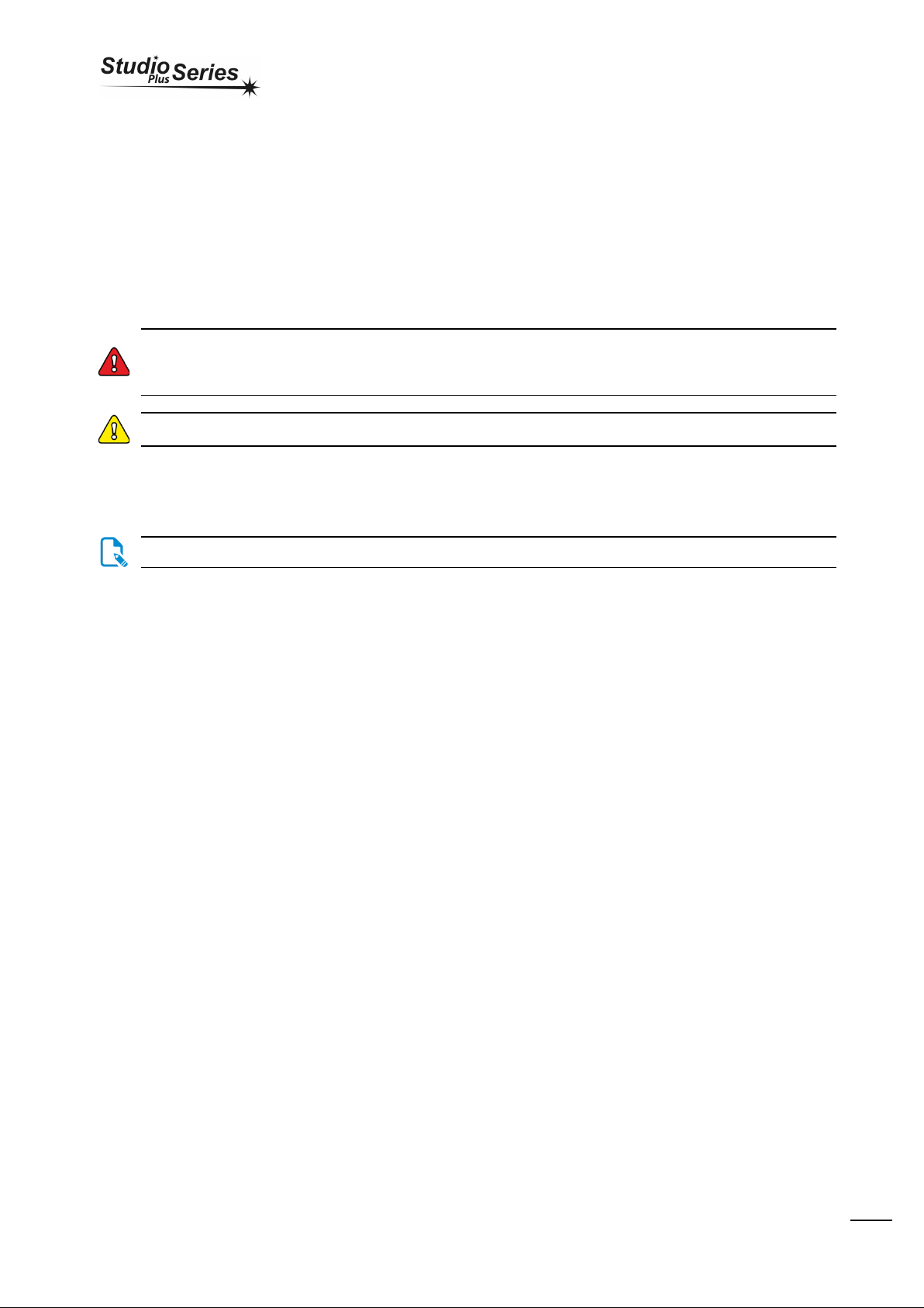
Operator interface
Controls and indicators
1. Stereo-microscope.
2. Inspection window with 1064 nm LASER ray filter.
3. Working chamber access doors.
4. Display with touch-screen for user setup parameters.
5. Emergency switch
6. USB key
7. Back connection (see paragraph)
8. Radiator cooling, do not cover, leave at least 5cm of free
space between the rear side and the wall.
9. Water level, for the proper equipment functioning,the
cooling level must always reach the MAX. Use bi-distilled
water ONLY for refilling/filling up.
10. Opening hosting pipes for filling/empting water tank.
Back connection
1. Resettable fuses
2. Power outlet
3. Main power switch
4. Shielding Gas/Air input
5. Foot switch connector
6. Remote interlock
2
6
4
5
1
3
1
2
3
4
5
6
7
8
9
10

Operator’s Handbook
Capitolo:
Use
15
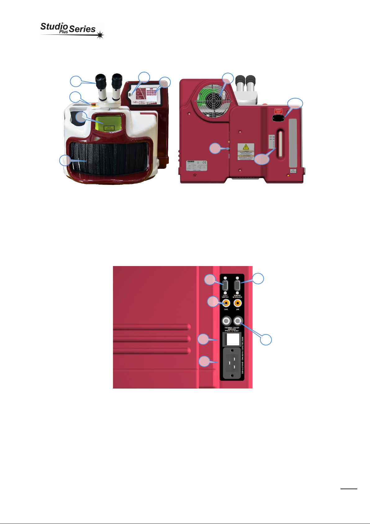
Inside welding chamber
1. LED lamp
2. SPOT diameter regulator
3. Rotary for settings the working parameters
4. Exhaust vapour grid
5. Plastic cone for Argon/Air output
Use
Please read the Safety Informationsection before using the device.
This paragraph explains how to use and the meaning of each menues loaded into the LASER welding unit.
Recommendations
Before beginning re gular use of the device it is recommended checking to ensure that it is in suitable working condition and that there are no
defective or worn parts. Perform any regular maintenance or repairs that may be required.
Positioning and ergonomics
Microscope eyepieces
Remove the caps that protect the stereo microscope, insert the eyepiecesand, once positioned properly in the housing, tighten the fixing screw.
Store the caps and eyepiece wrappers for future use.
One of the eyepieceshas a crosshair for sighting, this is usually positioned on the right tube of the stereo microscope. The diopter
dial may be adjusted: once the eyepiecesare positioned properly, rotate the dial clockwise or counterclockwise depending on the
focus you wish to achieve.Refer to the scale printed on each eyepiece.
1
2
3
1
4
5

Operator’s Handbook
Capitolo:
Use
16
Turning on the device
Move the power switch located on the front of the device to position I. Wait until the display shows the PIN entry screen.
Emergency Stop
The emergency button (see page. 14) is used to immediately switch off the device;This button is equipped with a safety feature,once it is
pressed it must be released to power the unit up again. Use the button only in case of danger or failure.
Example of practical use
This section describes practical use of the device and explains the laser welder menu.
PIN menu
In PIN Menù screen it’s possible to read the follow informations:
-Serial number of the unit
-Firmware revision of the display’s board
-Firmware revision of the microprocessor board
-Laser shots counter
Digit the numeric code “0000” and press “OK” to enter the stand-by
mode.
To make the machine operational, press and hold fo a second the
GREEN-key icon (Pic.1) and wait for it to become RED (Pic.2).
Operators may always interact with working parameters using the
touch-screen display. On the left side of the screen we can selectthe
energy of the impulse (intensity X duration of the impulse). On the
lower side of the display we can change the frequency of the shot in
time(shots per second). The maximum frequency is limited according
to the energy of the selected pulse.
USE OF THE ROTARY
Pressing the rotary switch (Pic.1), changes the val ue of the shot
frequency (l ower part of the di spl ay). I f operator spi n the rotary
instead, the val ue of the power set will be changed (l eft si de of the
display).

Operator’s Handbook
Capitolo:
Use
17
Tochange the spot diameter,the white lever must be slid up and
down. The smallest size of the spot diameter is the slider position
towards the machine. If the slider will be set towards the operator,
the spot diameter will be the biggest.
MANUAL PRIMING OF THE PUMP
In stand-by mode ONLY it’s possible to activate the pump making the water running in the circuit without starting the machine. This
operation is useful when tank is refilled after a full draining or in the first start up of the machine. Release the rotary to stop the pump work.
Press the rotary switch for 3 seconds, triggering the pump that turns
the water in the hydraulic circuit.
Accessory functions
Use of the air dispenser/shielding gas
All devices are equipped with:
1. A pipe jointed to the orientation of the air or protective gas.
2. Metal cone for protective gas coaxial flow.
3. Metal frame holding a protective glass.
If you wish, you can use one system or the other for the supply of shielding gas or air cooling.
The output of the gas / air is controlled by a solenoid valve, which is activated by depressingthe pedal every first frequency shot chain.
The inlet pressure must not exceed 4 bar. Do not connect pressure higher than the maximum allowed as this may damage the solenoid valve.
Example of use of the door slide door with cone:
This configuration is recommended for welding titanium, cobalt
chromium and steels in general.
The recommended pressure for use with protective gas (argon) is
0.1 / 0.2 bar, a soft blow is sufficient for the protection of articles
made of titanium, cobalt chromium and steels in general. Use the
special transparent cone inserted in the cone holder for conveying
the flow at the point of welding, as shown in Figure 1
Example of use of the slide door without dispenser:
This configuration is recommended for welding of objects in Silver
or Gold. It’s also advisable to connect compressed air (up to 4 bar)
to cool the metal during welding prolonged.
1
2
3

Operator’s Handbook
Capitolo:
Use
18
Maintenance
Please read the chapter on Safety Information before proceeding
Every maintenance operation, even minor ones for machine parts and the electrical system, requires the use of professionally
qualified personnel with training on the featuresof the device.
Original spare parts should be used. The use of non-original spare parts releasesthe Manufacturer from any liability.
Regular inspections
Check the integrity of the laser radiation safety glass on the KG3 viewing window and the leather curtains for hand access to the welding
chamber daily; if they need to be replaced, contact the manufacturer. Using the device with broken glass or without the curtains is DANGEROUS
and can cause health damage. Check the status and the integrity of the safety labels and IDplate every six months, contact the manufacturer if
they are discolored or illegible.
Checking the coolants
The equipment is provided of a cooling system working with bi-distilled water. The water shall be replaced at least every 12 months to avoid
having algae or limestone, which along time may deposit in the cooling pipes or in the LASER pool cavity.
Open up the rear pipes seat and pull out the 2 pipe caps. Pour the water (around 2 lts) into a basin.
Checking the filters
Air filter must be checked every month. Refer to ”routine maintenance” chapter for more ifnormation
Checking the protective glass slide
Verify at least once in a month the state of the glass placed inside of the welding chamber.
Routine Maintenance
Removal of the liquid
Pull the small pipe located underneath the LASERbase,remove the cap (see picture);place the basin under the opened pipe andwait the water
tank to be fully emptied (around 2 lts).
Operator’s Handbook
Capitolo:
Use
19
Filling/refilling the liquid
Use the syringe provided as a standard accessory with the equipment. Insert the syringe with double distilled water into one of pipes (any pipe)
and fill up to the level indicated on the panel. The equipment holds roughly 800ml of bi-distilled water. If overfilled the water will drain out from
the other pipe
Before closing the rear panel, verify the presence of the stoppers on the 2 small tubes.
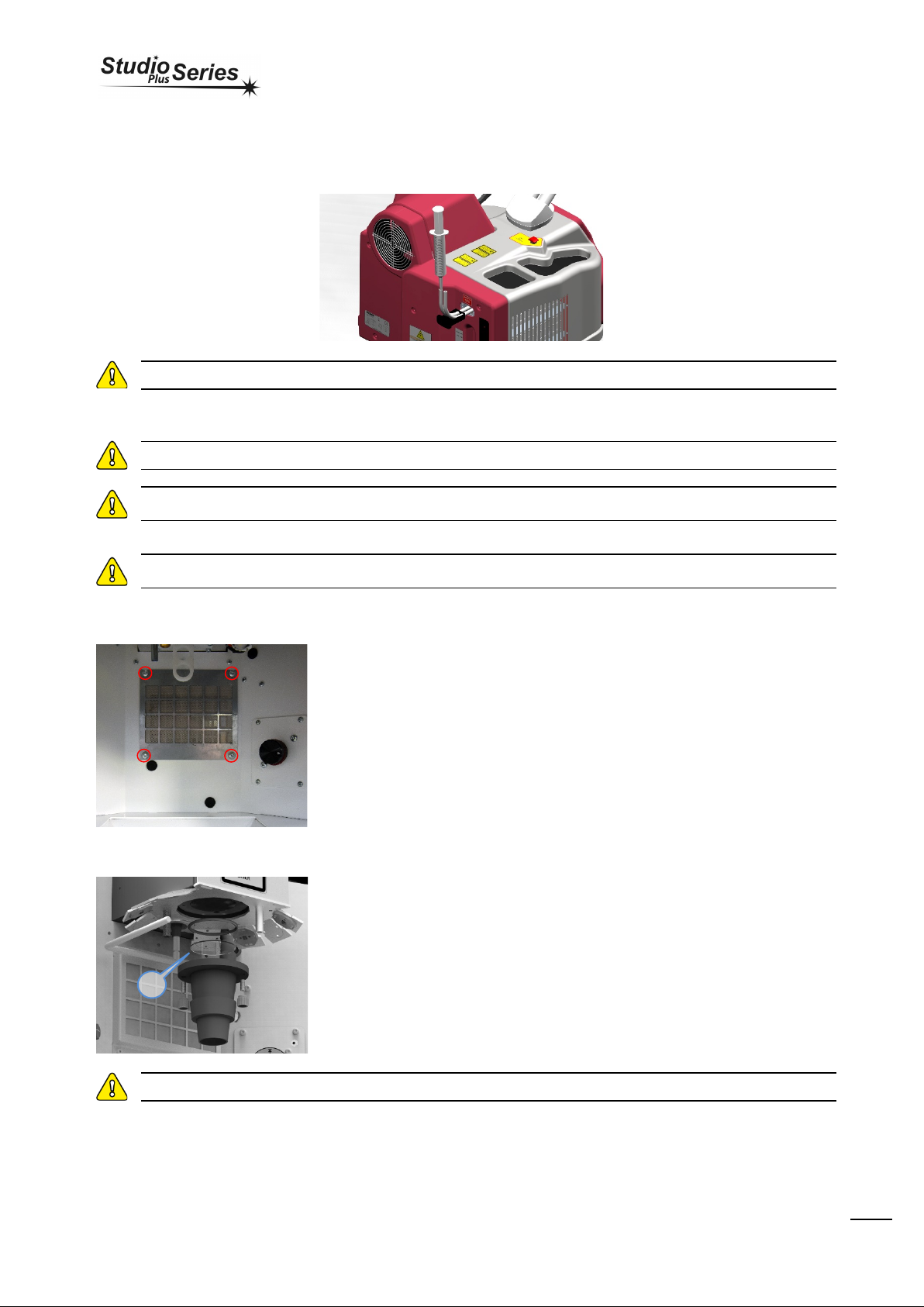
Cleaning the filters
Failure to maintain these filters can impair the device's performance.
Do not cover the vents on the device with cloth or other materials. Leave at least 10 centimeters of space between the v e n ts and
walls or obstacles. Failure to do so may compromise the efficiency of the device.
Do not cover any of the exhausting grids with clothes or other things and leave enough space (at least 10cm) from the rear grid and
the wall..
Cleaning of air filter
Unscrew the 4 screws shown in the photo. Clean up the filter with compressed air.
Replace the filter when it is very dirty;replace with a filter of the same type (Code RIC00041).
Replace regularly this filter because when full of dust and dirt may compromise the proper
functioning of the equipment.
Replacing the protective glass slide
Verify at least once in a month the state of the glass placed inside of the room (see photo).
To remove the door glass, unscrew the 2 screws indicated in the figure. In case the glass is
saturated of metal sprays or damaged, replace it with one new (Code ATE00018). 1 - Check
also the black paper (Code D2139193) cone inside the plastic light diffuser, to get the best
performance of the illumination this paper must be in good condition, replace it when
necessary.
If the glass is very dirt or damaged, the power of the equipment can go down until to 80% regarding the normal performances.
Checking alignment
•Set the following parameters 1.0KW, 1.0mS 0Hz and minimum SPOT size.
•Insert a piece of flat metal and fire a shot.
•Check the location of the spot produced against the crosshair; if the spot intersects the crosshair in the center is not necessary to correct the
alignment.
1

Operator’s Handbook
Capitolo:
Use
20
Correcting the alignment
Take great care to avoid inadvertently activating laser emission when performing realignment operations.
With the device in standby, locate the screws close to the cone
slide holder as shown in the illustration.
Never touch the screw no. 3, the one between the other two
screws without a guide. This screw has been placed there by the
manufacturer. Using the 3 mm hex key, loosen screws 1 and 2.
•Turning screw no. 1 moves the welding point
horizontally.
•Turning screw no. 2 moves the welding point
vertically.
Use slight movements and small shots on a piece of metal to
verify the correct positioning of the crosshairs. Continue until the
crosshairs coincide perfectly with the welding spot.
The screws for the alignment have brass guides to make them
easier to identify.
To facilitate the alignment procedure, the crosshairs bear the symbol ▲, which indicates the highest point. make sure th is
symbol is pointed upwards and complete the alignment as described above.
Only use the viewing window to inspect the inside of the welding chamber, it is a good rule to put the device in standby before
adjusting the screws to preventaccidentally activating the laser.
Repairs
Repairs should only be made in the eventof an anomaly, see the chapter Diagnosticsfor more information.
Repairs should only be performed by Neutec USA personnelor personnel it has authorized.
Recommendations
The following recommendations will optimize the efficiency of the device:
•The device should be stored in a location that is not too hot and away from heat sources; the higherthe temperature of the envir onment,
the lower the efficiency of the cooling circuit/heat exchanger.
•Keep away from equipment that produces moisture or dust, such as sand blasters, vaporizers,etc.
•Follow the directions in the manual, and read the sections on safety and maintenance.
•Use only original spare parts specified in this manual.
•Only use deionized water as a cooling liquid, the use of water or liquids different from that indicated may affect device operation.
•Ensure that safety devices are working properly.
1
2
3
This manual suits for next models
2
Table of contents
Popular Welding System manuals by other brands

Lincoln Electric
Lincoln Electric BURNY KALIBURN Spirit II 275 user manual

Miller
Miller Dynasty 280 owner's manual

Magmaweld
Magmaweld SMART Series user manual

EWM
EWM OW ASM 2.DV PHOENIX PROGRESS K operating instructions

ESAB
ESAB ET 186i AC/DC operating manual

iWeld
iWeld POCKETTIG 200 AC/DC DIGITAL user manual

Lincoln Electric
Lincoln Electric RANGER GXT IM856 Operator's manual

Metal Man
Metal Man M190 Operator's manual

WIELANDER+SCHILL
WIELANDER+SCHILL Inverta Puls IP6-2 ACT Operation manual

stud welding products
stud welding products StudPro 2500 Operation manual

CIGWELD
CIGWELD WeldSkill 120 Turbo Operation manual

ESAB
ESAB ESABMig 325 Service manual


