NEWCOMB SM-310-4 User manual
PnoTo FACT' FolJ"t
S
ff9
o€
-t_
OE
rr ul
|a
dT
oo
:s
5e
(J('
i; r*
Fg
E;
oe
I rrr
FrUI
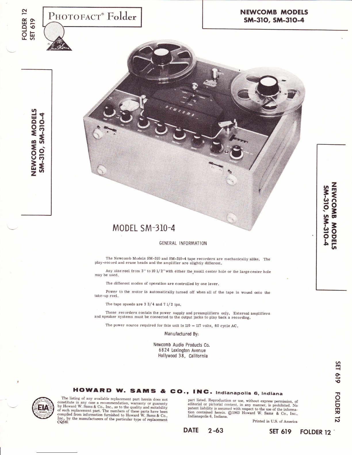
M0D[L SM-3r0-4
GENERAL INFORMATION
The Newcomb Models SM-3I0 and SM-3I0-4 tape recorders are mechanically alike. The
play-record and erase heads and the amplifier are slightly different.
Any sizereel from 3" to l0 l/2"with either the small center hole or the largecenter hole
may be used.
The different modes of operation are controlled by one lever.
Power to the motor is automatically turned off when all of the tape is wound onto the
take-up reel.
The tape speeds are 3 3/ 4 and ? I/2 ips.
These recorders contain the power supply and preamplifiers only. External amplifiers
and speaker systems must be connected to the output jacks to play back a recording.
The power source required for this unit is lI0 - U? volts, 60 cycle AC.
Manufactured By:
Newcomb Audio Products Co.
6824 Lexington Avenue
Hollywood 38, California
HCDWARD W. ISAIUlts &
The listing of any available replacement part herein does not
constitute r! .ny case a_recommendation, warranty or guaranty
by Howard W. Sams & Co., fnc., as to the quality ana sriitanUty
of such replacement part. The numbers of ihese parts have beeir
compiled from information furnished to Howard W. Sams & Co.,
L"!r -!V the manufactwers of the particular type of replacemeni
cQ56l
(GO., ltG. tndianapolis Gi, Indiana
part listed. Reproduction or use, without express permission, of
editorial or pictorial content, in any -a'nei, is piohibiied. No
patent liability is assumed with respect to the use of th" i.rfor-"-
tion contained herein. 01963 Howard W. Sams & C;., i;".,
Indianapolis 6, Indiana. Prinied in U.S. of America
(
m
{
O.
€
TI
o
|-
I
m
F
}\)
NEWCOMB MODELS
sM-31o, stl^-3lo-4
DATE 2-63 sET 619 FOTDER 12

13
33
14
16
FIG. I TOP VIEW OF MECHANISM WITH COVERS AND DRIVE ASSEMBLY REMOVED
FUNCTION OF CONTROLS
Tape Control Lever Channel I and Channel 2 - Line
Sel€cts themode of operation whenplaced in the Controls the record Level when recording from
marked positiona on the head cove!. an external source.
Speed Fu nction
Depress thls button while tie motor is running Selects either the record or playback mode of
to select tlte correct speed. operation.
Left-Hand Take-up Guide outPut
The take-up guide is connected to the automatic Turns the power on to the recorder and regu-
motor swltchald holds the switch closed when tape is late6 the output volume.
threaded on the recorder. When no tape is on the re-
corder, the take-up guide is pulled forward by spring Balance
tenslon and opens the automatic motor snritch.
channel I and channel 2 - Mike Balances the two channels when plaving stereo'
controls the record level v/hen recording from Sglgctor
a microphone. Selects the channel or chalnels for recording
or playback.
FUNCTIONS OF JACKS
Mike I channel 2lnput
Connect microphone to this jack for Channel I Fo" cormecting an external Gource to make a
recordlngs. recording on Channel2.
Channel I lnput Channel 2 output
connect an external recording source for chan- For connecting an external ampliJier tor pl.ay_
ne1 I recording. back.
Channel I Output Mike 2
For connecting an external ampliJler for play- For making recordings on Channel 2.
back.
Monitor
Fo! connecting headphones to monito! a re-
cordlng.
PAGE 2
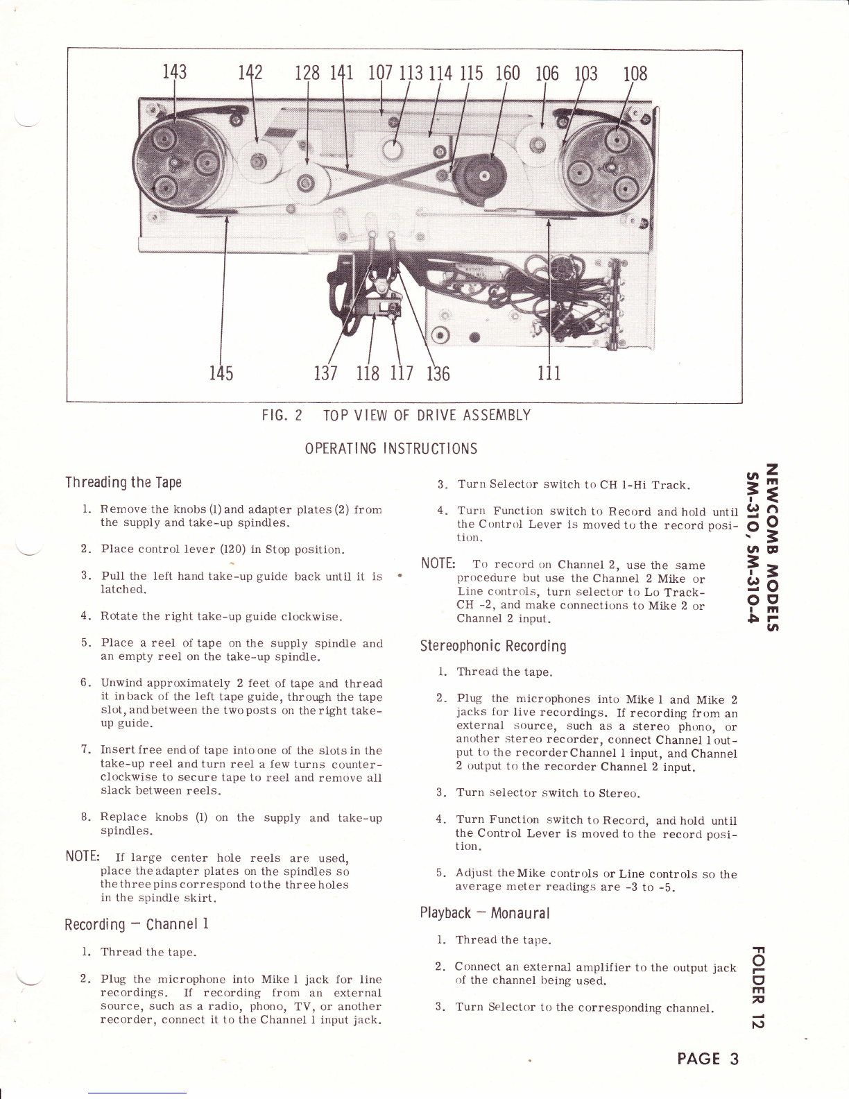
128 141 107 1 13 1 14 115 160 106
. a:r:
{*B
\:v
137 118 IT7 136
FIG. 2 TOP VIEW OF DRIVE ASSEMBLY
OPTRATI NG I NSTRUCTIONS
Threading the Tape
l. Remove the knobs (I)and adapter plates (2) from
the supply and take*up spindles"
2. Place control lever (120) in Stop position.
3. PuII the left hand tat<e-up guide back until it is .
latched.
4. Rotate the right take-up guide clockwise.
5. Place a reel of tape on the supply spindle and
an empty reel on the take-up spindle.
6. Unwind approximately 2 feet of tape and thread
it inback of the left tape guide, through the tape
slot, andbetween the twoposts on the right take-
up guide.
7. Insert free end of tape into one of the slots in the
take-up reel and turn reel a few turns counter-
clockwise to secure tape to reel and remove all
slack between reels.
8. Replace knobs (l) on the supply and take-up
spindles.
NOTE: If large center hole reels are used,
piace the adapter plates on the spindles so
the three pins correspond tothe three holes
in the spindle skirt.
Recording - Channel I
I. Thread the tape.
2. Plug the microphone into Mike I jack for line
recordings. If recording from an external
source, such as a radio, phono, TV, or another
recorder, connect it to the Channel I input jack.
3. Turn Selector switch to CH l-Hi Track.
4. Turn Function switch to Record and hold until
the Control Lever is moved to the record posi-
tiott.
NOTE: To record on Channel 2, use the same
proceciure but use the Channel 2 Mike or
Line ct_rntrols, turn selector to Lo Track-
CH -2, and make connectit.rns to Mike 2 or
Channel 2 input.
Stereophon ic Recordi ng
l. Thread the tape.
2. PIW the microphones into Mike I ancl Mike 2
jacks for live recordings. If recording from an
external source, such as a stereo phono, or
ar"rother stereo recorder, connect Channel I out-
put to the recorderChannel I input, and Channel
2 output to the recorder Channel 2 input.
3. Turn selector switch to Stereo.
4. Turn Functicln switch to Record, anci hold untii
the Control Lever is moved to the record posi-
tion.
5. Adjust theMike controls or Line controls so the
average meter reaclings are -3 to -b.
Playback - Monaural
l. Threaci the tape.
2. Connect an external amplifier to the output jack
of the channel being used.
3. 'Iurn Selector to the corresponding channel.
.^z
FE
G)fl
.69
rN CE
Ee
oe
rm
Frta
TI
o
r
I
1Tl
F
N
PAGE 3

4. Pull Control Lever to Listen,
5. Adjust the Output control to the desired listening
le v eI.
Playback - Stereo
I. Thread the tape.
2. Connect external amplifiers to the output jacks.
3. Turn Selector to Stereo.
4. PuIl Control Lever to Listen.
5. Adjust the Output control to the desired listening
Ievel.
6. Adjust the Balance control so the output of each
channel is equal.
Dual-Track Recording
When all the tape has been wound onto the take-
up spindle, remove the full reel; turn it over and
place it on the supply spindle. Place the empty reel
on the take-up spindle, rethread the tape, and pro-
ceed with ttrerecording. The first track canbe played
back without rewinding.
Quarter-Track Recording
Turn the Selector to CH i Hi Track. Thread the
tapeon the recorder. When theiirst track isrecorded
remove the full reel from the take-up spindle, turn it
over and place on the supply spindle. Rethread the
tape and record the second track. After the second
track is recorded, turn the Selector to Lo-Track -
CH 2. Remove the full reel of tape, turn it over and
place on the supply spindle. Rethread the tape and
record the third track. After the third track is re-
corded, remove the full reel, turn it over and place
on the supply spindle. Rethread the tape and record
the fourth track.
The tape can be played back in the same manner.
Reverse
When the Control Lever is moved tethe Reverse
position, the tape will be rewound onto the supply reel,
Forward
Portions of program material may be skipped
over toadesired spot when theControl Lever ismoved
to the Forward position,
ListenTo play back a recording, move the Control
Lever to Listen.
Record
To set the tape in motion for recording, move
the Control Lever to Record.
Erasi ng
A recording is automatically erasedwhile a new
one is being made. To erase a tape without putting a
new recording on it, unplug all input connections, turn
ali controls to their lowest level, turn the Function
switch to record and hold until the Control Lever is
pulled into Record position. The tape will now run by
the erase head and any material on the tape will be
erased.
DISASSEMBLY
To Remove Recorder from Cabinet
I. Remove two screws from the front and back of
cabinet and lift recorder out.
To Remove Tape Transport and Power Supply
I. R.emove the spindle plates (3).
2. Rem.ove the knob (3I) from toggle section (lI?).
3.
R
8.
Remove head covers (B) and (9) and belt access
cover (6).
Lift push-pull rod (98) out of the slot in the idler
carriage (]07).
Unplug the equalizer plugs from the amplifier.
Unhook the supply drag brake cord.
Unhook the motor switch cord.
Unhook spring from take-up tensioner (24).
Remove flywheei drive belt (71) from motor
pulley (160).
Remove counter drive belt (65).
Il. Remove the screw holding the tape transport
and power supply to the amplifier.
12. Remove four screws from the top assembly.
13. Remove the hex nut and lockwasher holding the
power supply chassis to the lower flywheel
mounting piate.
14. Slide the transportback andunplug theamplifier
power plug.
15. Lift the transport and power supp).y from the
top assembly and amplifier.
To Remove Amplifier
1. Remove control knobs.
2. Remove monitor switch from top assembly.
3. Remove four screws from amplifier shield and
remove shield.
4. Unsolder head leads.
5. Unpiug meters.
6. Remove twoscrews from top assembly and then
lift ampiifier from top assembly.
4.
6.
7.
9.
I0.
PAGE 4
I
ADJUSTMENTS
Record- Playback Head Azim uth
l. Thread a standard test tape on the recorder.
2. Connect an output meter to the output of the re-
corder.
3. While playing back the I0,000 cycle tone, adjust
the Phillips head screw at the rear of the head
mount until peak output is obtained.
4. Check the output of the second channel. If the
output varies too much between channels, adjust
to give best results on both channels.
BeltFlipper(ll4)
If the belt flipper (114) is too low, loosen the set
screw and raise it so it wiII not rub the capstan drive
belt (71). If too high, Iower so the lift-off finger on
belt flipper will not rub belt.
Cut-0ff Switch
l. Place the recorder in a vertical position.
2. Loosen the thumb nut on motor capacitor assem-
blv.
3. Place the retractor post on cut-off arm (48) so
it is one-eighth of an ineh from the head cover
( B).
4. Tighten thumb nut.
5. With the recorder in the Play position and re-
corder setting in a vertical position, the pres-
sure of the tape contactor against the tape should
be enough to support the weight of a one cent
piece resting on the retractor post.
6. Make sure the cut-off arm shaft assembly has
.005" end play in its bushing.
Spindles
I. To align the spindles in the sides to side direc-
tion, loosen or tighten the two screws at the
bottom, toward the center oi the deck.
2. Place a l0 L/ 2" reel on each spindle.
3. Adjust the top screw until the reel runs free of
both flanges. This adjustment is for top to
bottom plane.
Stopping Brakes
l. Loosen the screw through the slotted hole in the
anchor bracket (165) and move the anchorbracket
for the initial adjustment.
2. Bend the brake adjuster tab on brake band as-
sembly (145 or lll) with a pair of pliers, to cause
the brakes to come on sooner or vice-versa.
Care must be taken to insure both brakes are
adjusted eqr-rally.
Take-Up Tensioner ( 24)
l. Leave .005" end play between the eccentric (81)
and bearing (83).
2. Position the take-up tensioner (24) so it will be
at a 30 degree angle with respect to the tape
deck.
Supply Drag Brake
l. Adjust the drag pulley bracket (l5a) so the ten-
sion spring (I52) will be stretched approximately
5/32" when in the play position.
Take-Up Torque
l. Place a ?" reel on the take-up spindle.
2. Place the recorder in a vertical position.
3. Fasten a L-L/2 ounce weight, such as a tire
. balancing weight, to the outer edge of the reel.
4. Place the Tape Control lever in the Play posi-
tion.
5. If the take-up torque, 'which should be 4 to 6
ounces, does not balance out ihe effect of the
weight, slide the metal clip on the idler carri-
age (107) closer tothe take-up spindletoincrease
the spring tension.
Rewind Torque
l. Place a ?" reel on the supply spindle.
2. Place the recorder in a vertical position.
3. Fasten a 4-ounce weight, such as a tire balanc-
ing weight, to the outer edge of the reel 90 de-
grees from the vertical axis. The weight will
exert a downward force of 13-inch-ounces. The
re'wind torque should be 12 to 13 inch-ounces.
Record Switch Latch
If the pressure arm (22) does not latch properly
with the switch, bend the endof the pressure armpast
the notch until they latch properly.
Pressure Roller
l. Place a loaded ?" reel on the supply spindle.
2. Place the recorder in a vertical position.
3. Fasten a4-ounce weight, such as a tire balanc-
ing weight, to the inside edge of the reel.
4. Turn the power on and place the Tape Control
lever in the Record position. The 4-ounce
weight should balance out the capstan pu1l. If it
does not, proceed as follows:
a. Loosen the lock screw on the pressure arm
(22).
b. Turn the6-32 Allen head set screw until the
4-ounce weight and capstan pull is balanced
out. Make this adjustment with tape running
through the recorder.
c. Retighten the lock screw.
.-z
F3
G)6
.69
UIF
ia
ott
r |tt
5rUI
.n
o
F
(f
m
F
N
PAGE 5
z.
l.!J
o
E,
O
tf,
./t
lJ.j
E
I
=
u.l
=
o
o
6
VI
L/t
at'l
(J
o-
=
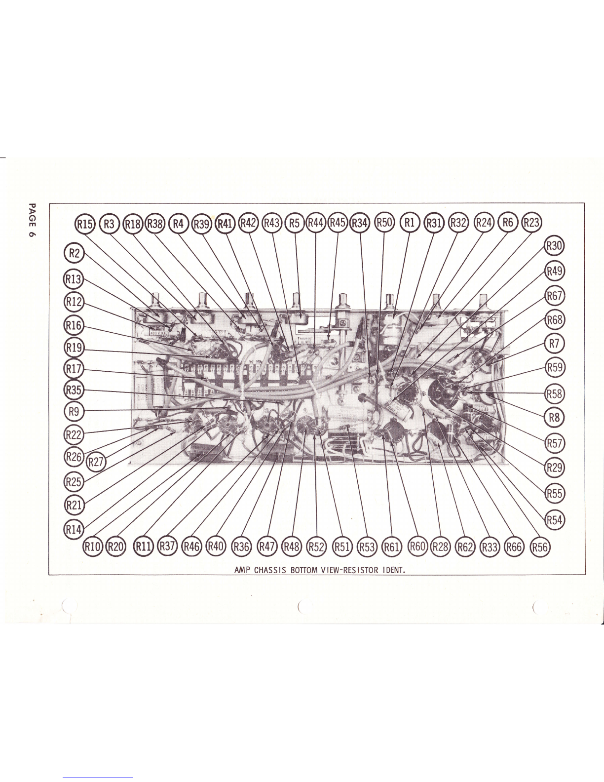
PAGE 6

AMP CHASS IS BOTTOM V IEW.CAPACITOR & MISC. IDENT.
BOTTOM
DR IVE MECHAN I SM
PAGE 7


FIG. 3BONOM V IEW OF MECHAN ISM W ITH DR IVE ASSEMBLY REMOVED
138 139 154
ry*#
FIG. 4BOTTOM V lEW OF DR IVE ASSEMBLY
CLTAN ING
Pressure roller (20), erase head (33), record-
playback head (14), and tape guides (16) accumulate
tape oxide as it passes these parts. Use a soft cloth
and alcohol to remove it. After long periods of oper
ation, a buildup of dirt and brake lining fuzz will
accumulate on the brake drums. Use a cloth and al-
cohol to remove it.
LUBRICATION
The bearings are the setf-lubricating type and
t3
..69
gtE
Ea
oe
Itll
5rIa
should not need lubrication for a long period of time
under normal operating conditions. Need for lubri-
cation will be evident by mechanical noise or slow
operation. Use SAE30-type motor oiland lubricate as
follows:
Motor - l0 drops at each end.
Belt idler pulleys - I drop each.
Capstan - l0 drops at top and bottom.
Counter - I drop on shaft at bearing.
Pressure roller - I drop to shaft.
CAUTI0N: Do not overtubricate.
TI
o
F
I
m
F
J
N)
PAGE 13
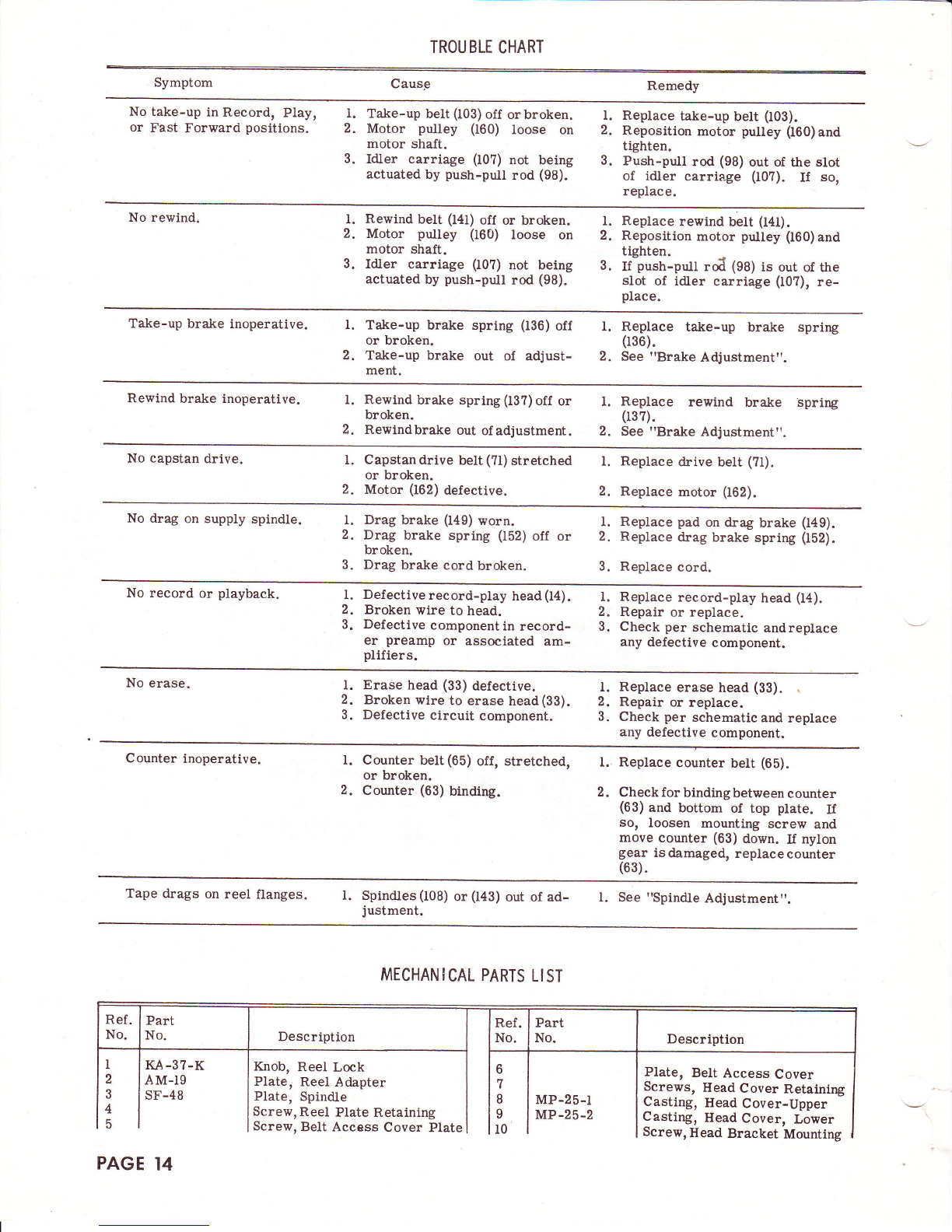
TROUBLE CHART
Symptom Cause Remedy
No take-up in Record, Play,
or Fast Forward positions. Take-up belt (103) off orbroken.
Motor pulley 060) loose on
motor shaft.
Idler carriage (10?) not being
actuated by push-pull rod (98).
Replace take-up belt (I03).
Reposition motor pulley (160) and
tighten.
Push-pull rod (98) out of the slot
of idler carriage (10?). If so,
replace.
I.
2.
3.
1.
2.
3.
No rewind. I. Rewind belt (l4l) off or broken.
2. Motor pulley (160) loose on
motor shaft.
3. Idler carriage (107) not being
actuated by push-pull rod (98).
l. Replace rewind belt (l4t).
2. Reposition motor pulley (160)and
tiEhten.
3. tf'push-pil rd (98) is out of the
slot of idler carriage (10?), re-
place.
Take-up brake inoperative. Take-up brake spring
or broken.
Take-up brake out of
ment.
Replace take-up brake spring
036).
See "Brake Adjustment".
I.
2.
1.
2.
(136) off
adjust-
Rewind brake inoperative. I.
2.
Rewind brake spring (13?) off or
broken.
Rewindbrake out of adjustment.
Replace rewind brake spring
037).
See "Brake Adjustment".
1.
2.
No capstan drive. Capstan drive belt (?1) stretched
or broken.
Motor (162) defective.
Replace drive belt (?l).
Replace motor (162).
l.
2.
l.
2.
No drag on supply spindle. Drag brake (149) worn.
Drag brake spring (t52) off or
broken.
Drag brake cord broken.
Replace pad on drag brake (149).
Replace drag brake spring (152).
Replace cord.
l.
2.
3.
I.
2.
3.
No record or playback. Defective record-play head (14).
Broken wire to head.
Defective component in record-
er preamp or associated am-
plifiers.
Replace record-play head (I4).
Repair or replace.
Check per schematic andreplace
any defective component.
l.
2.
3.
l.
2.
3.
No erase. I.
2.
3.
l.
2.
3.
Erase head (33) defective.
Broken wire to erase head(33).
Defective circuit component.
Replace erase head (33). \
Repair or replace.
Check per schematic and replace
any defective component.
Counter inoperative. Counter belt (65) off, stretched,
or broken.
Counter (63) binding.
Replace counter belt (65).
Check for binding between counter
(63) and bottom of top plate. U
so, loosen mounting screw and
move counter (63) down. If nylon
gear is damaged, replace counter
(63).
t.
2.
I.
2.
Tape drags on reel flanges. l. Spindles (108) or (143) out of ad-
justment. l. See "Spindle Adjustment"
MECHANICAL PARTS LIST
6
7
I
I
i0
I
2
3
4
5
KA-37-K
AM-Ig
sF-48
Knob, Reel Lock
Plate, Reel Adapter
Plate, Spindle
Screw, Reel Plate Retaining
Screw, Belt Access Cover Plate
Plate, Belt Access Cover
Screws, Head Cover Retaining
Casting, Head Cover-Upper
Casting, Head Cover, Lower
Screw, Head Bracket Mounting
MP-25-1
MP-25-2
Description
PAGE 14
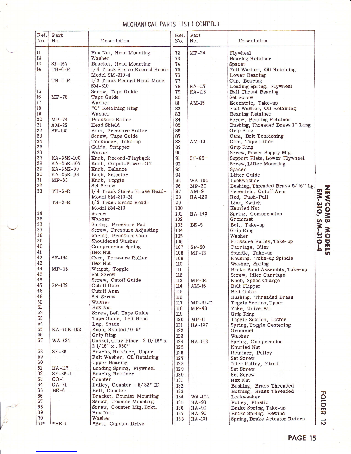
MECHANICAL PARTS LIST ( CONT'D. }
l5
I6
l?
IB
l9
20
2L
22
23
24
25
26
27
28
29
30
31
32
33 r*
.69
(aE
Ee
o9
rI'l
5rUI
'n
o
I
m
n
N)
72
?3
74
75
?6
11
78
?9
80
8l
82
83
84
85
86
87
88
89
90
91
s2
93
94
95
96
91
98
99
100
l0l
r02
103
r04
r05
106
t0?
r08
109
lr0
lll
LLz
113
114
tl5
116
1l?
118
ll9
120
I2r
122
123
t24
125
126
t27
lrza
lrzs
| 130
I 13t
I rsz
I rss
I rs+
lrss
I rso
lrsz
lrsa
34
35
36
3?
38
39
40
4L
42
43
44
45
46
47
48
49
50
5l
52
53
54
55
56
5?
58
59
60
6l
62
63
64
65
66
67
68
69
?0
?l*
sF-167
TH-6-R
TH-?-R
MP.?6
MP-?4
Al0'I-22
sF-165
KA-35K-100
KA-35K-10?
KA-35K-99
KA-35K-lot
MP-33
TH-5-R
TH-3-R
sF-r64
MP-45
sF-l?2
KA-35K-IO2
wA-134
SF-86
HA-II?
sF-86-1
co-r
GA-3I
BE-6
Hex Nut, Head Mounting
Washer
Bracket, Head Mounting
L/ 4 Track Stereo Record Head-
Model SM-310-4
l/ 2 Track Record Head-Model
SM-3IO
Screw, Tape Guide
Tape Guide
Washer
"C" Retaining Ring
Washer
Pressure Roller
Head Shield
Arm, Pressure Roller
Screw, Tape Guide
Tensioner, Take-up
Guide, Stripper
Washer
Knob, Record-Playbqck
Knob, Output-Power-Off
Knob, Balance
Knob, Selector
Knob, Toggle
Set Screw
I/ 4 Track Stereo Erase Head-
Model SM-310-M
L/ 2 Track Erase Head-
Model SM-310
Screw
Washer
Spring, Pressure Pad
Screw, Pressure Adjusting
Spring, Pressure Cam
Shouldered Washer
Compression Spring
Hex Nut
Cam, Pressure Roller
Hex Nut
Weight, Toggle
Set Screw
Screw, Cutoff Guide
Cutoff Gate
Cutoff Arm
Set Screw
Washer
Hex Nut
Screw, Left Tape Guide
Tape Guide, Left Hand
Lug, Spa.de
Knob, Skirted t'0-9rr
Grip Ring
Gasket, Gray Fiber - 2 lI/ 16 " x
2 L/L6" x .050"
Bearing Retainer, Upper
Felt Washer, Oil Retaining
Upper Beariry
Loading Spring, Flywheel
Bearing Retainer
Counter
Pulley, Counter - 5/32" D
Belt, Counter
Bracket, Counter Mounting
Screw, Counter Mounting
Screw, Counter Mtg. Brkt.
Hex Nut:
Washer
*Belt, Capstan Drive
MP-24
HA-II?
HA-ll8
AM-I5
AM-10
SF-65
wA-r04
MP.2O
AM.9
HA-120
HA-143
BE-5
sE-50
MP-12
MP-34
AM-16
MP-3I-D
MP-48
MP-II
HA -I2?
HA-I43
FlywheeI
Bearing Retainer
Spacer
Felt Washer, Oil Retaining
Lower Bearing
Cup, Bearing
Loading Spring, Flywheel
Ball Thrust Bearing
Set Screw
Eccentric, Teke-up
Felt Washer, Oil Retaining
Bearing Retainer
Screw, Bearing Retainer
Bushing, Threaded Brass l" Long
Grip Ring
Cam, BeIt Tensioning
Cam, Tape Lifter
Grip Ring
Screw, Power Supply Mtg.
Support Plate, Lower Flywheel
Screw, Lifter Mounting
Spacer
Lifter Guide
Lockwasher
Bushing,Threaded Brass 5,/16" Lg
Eccentric, Cutoif Arm
Rod, Push-Pull
Link, Switch
Knurled Nut
Spring, Compression
Grommet
BeIt, Take-up
Grip Ring
Washer
Pressure Pulley, Take-up
Carriage, Idler
Spindle, Take-up
Housing, Take-up Spindle
Washer, Spring
Brake Band Assembly, Take-up
Screw, Idler Carriage
Knob, Speed Change
Belt Flipper
BeIt Guide
Bushing, Threaded Brass
Toggle Section, Upper
Yoke, Universal
Grip R.ing
Toggle Section, Lower
Spring, Toggle Centering
Grommet
Washer
Spring, Compression
Knurled Nut
Retainer, Pulley
Set Screw
Idler Pulley, Fixed
Set Screw
Set Screw
Hex Nut
Bushing, Brass Threaded
Bushing, Brass Threaded
Lockwasher
Pulley, Plastic
Brake Spring, Take-up
Brake Spring, Rewind
Spring, Brake Actuator Return
wA-104
HA-96
HA-90
HA-90
HA-l3l
_i-
*BE-I
PAGE 15
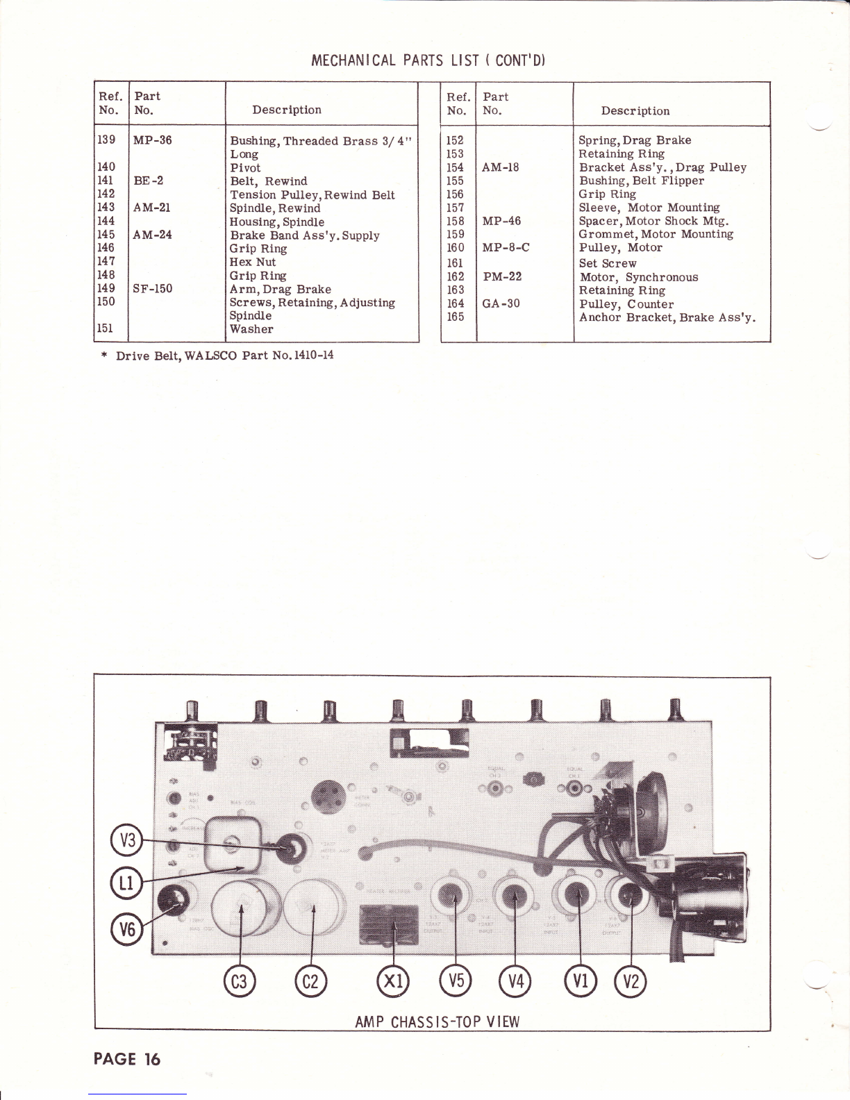
MECHANICAL PARTS LIST ( CONT'D)
..*
ffi
,;ffi;
4Fp:
AMP CHASSIS-TOP VIEW
Description Description
MP-36
BE-2
AM-2I
A M.24
sF-150
Bushing,Threaded Brass 3/ 4"
Long
Pivot
BeIt, Rewind
Tension Pulley, Rewind BeIt
Spindle, Rewind
Housing, Spindle
Brake Band Ass'y. Supply
Grip Ring
Hex Nut
Grip Ring
Arm, Drag Brake
Screws, Retaining, A djusting
Spindle
Washer
AM-I8
MP-46
MP-8-C
PM.22
GA -30
Spring, Drag Brake
Retaining Ring
Bracket Assty. , Drag Pultey
Bushing, Belt Flipper
Grip Ring
Sleeve, Motor Mounting
Spacer, Motor Shock Mtg.
G rommet, Motor Mounting
Pulley, Motor
Set Screw
Motor, Synchronous
Retaining Ring
Pulley, Counter
Anchor Bracket, Brake Ass'y.
* Drive BeIt, WALSCO Part No.l4I0-14
PAGE 16

F
o
F
U
:
U
I
J
c
U
4
tt,
Y
E
=
u
e
z.
<o
iz
v-
&n
o?
='d
QZ
ej-
r
o
z
F
d,
F-
xEEgExExs-EENE
=BSE33SB=5sBE
Et g!q!At!?qlF6oodNolll
6ldNNNNNNOOOOO
etr &Etrtrdddcdd!d
F
6
F
z
u
2
U
U
J
G
u
e
v,
Y
e
=
U
e
x
N
@
z
i2
!zL
5i
)"
ct
z
U
dl-
-d c
o
z
F
d, :gEFxHsxsHsse
fre -OHNO$66eOOO*
e.iiHdiH----NN
trtr!ttrtrtrtrtre&e&t,
F
o
F
z
r
=
U
(J
I
A.
U
4
t9
o'
=5
-s
'1 Fl "1 ":,1
<r$sssFl
u;^ ;{ ;; X d (o
sE!333N
a€ ?^?^9^?-s d E
s.,^ o-B o-t "-g ogEgd-g{g
:':J' g@<{ntf @{16€t@QnO@
*;$ $o$oso$@@oNoNo
HB Sd$dgd$d$d$d$d
ed
d, z-
Ia
Uf;
55545555*Aar ?i
tq(Jn(Jtrl(Jooxr-)(a ch
xnhFlhFlhFlYn= H
##fni3sgi"3,.
PiliHiHiHgHHEHE
oo @q) 0() @o oosasn
F
<d
uiz
Op
e, c,
JL
IiAi*i*{*{u{*
ro.
<o
4t
22
ud
E+ E H F E g
^-f; T .r c'\ ct d
qHF:"EdtEd
E;X.Y?Y;EA
3;Hs333s:-s33iRx F
@-u, !N6N@N@NONFi)-.
AgEB dBABABAAd'E F
g,
o-
B<
Ho-
XvMXM!4
;jjiSJoo
? ???????
ccccfr&&d
iur
32
p< 8E58EMx
@6@@a:@@
NNNNN6TN
v14
oo
oo
60
u
o
)
N
4;-l;
i:55 N
AE* E E "+;
HltF'lg<
-: tD ! o d o a
g5g5Effff
o
I
o
rN
iDo
EE
at
oo
fe StQdo<.n@r@
frtrtrdddtr&
d
qt
:€,
,2
.
q,
o
rnE
4,=
o;
b-E
t/t o
ul E'
s=
C{
(9
EI
E
ct
'
-t
Q'
6
:o
6
'=
€t
-ct
6
v!8
A=
v
4A
hs
Za
Os
r,l i
'Ft
\.
I
q,
a
E
!E
o''
F:
.:
o
k
C)
-' c)
OE
-oo
tro
LO
f,B
!o
EZ
o
o.
rD ru
zE
+z
?
g
o
g
rtl
c,
o
ts
I
G
I
o
tlt
x
u-
z
o
F
L
-
e,
(J
rn
tlt
o
o
z
=
Fl
o
&
ti
A
z
ID
:
*r*
Fg
(aE
Ee
?H
DFla
.--J
tt
F
c,
4
o-
=
r/t
c,
o
=
(J
il
I
o
tlt
x
l!
tt
c
o
E
I
4
I
I
t-
J
o
c
l-
(J
tlt
J
tlt
vt
llt
cl
o
o
J
z
I
l,I
06
vt
I
ut
-
IL
=
(,
llt
4
4
ul
3
o
4
rt!
tlt
to
f
F
TI
o
F
g
ttt
F
}9
F
6
F
z
u
=
u
U
I
A
U
d
!!d
o'
<t
C.d
A<
rrd ERFEEEFfiHFFqrf.;
HiigiiEEEE6HggEH*E
ai
o2
-{ts
=3
6O NN
H(o.O NN
O ONN dN
ltr :l|@O 6@
oioiiioiioooog9o
s>d::>6>E5ddsET9
P{H P{ tsl H f4 AHFI A P{ A F<A E A
uoo(5o(,o(J()o(,(5()(,0(J
Oc
Yz
UF
=:
uA
$ $NN NN
-d 6;dEd eili r
q;HiEEFiiEF++$ T
ari.ari clci aricia aaoa d,
848S4888888888 B
-rc c
dv2
z4
g:! €@ NN F
sd aEE EE ---*s
@$n$o@n@@t Fi.r.:'o@
*ggBBBEBBEEEEEET
Eo'l o oo l.l o o i "1Fl i'l X o
!A
JJ
<L
E--
6f 9?$NsNNTNN:a*:fi 9?
T???EE?SS??TFfi E
OEOrr@@A@oAAAAA A
aaooaaaoanaaoa n
!,
8?
<e
@@ NN F
si-i33 3E gi
A6EEEEaEEgegEEdE
HEaEEEadEaaaaaEE
,1,
!z
d
z
g
d
o
t
tr
&
o
oo oo a>
oo
o o€o dN
$H$@@ NN ET
8.18.18.q g qt g gEEFS 3.
Ei F@OOTNO:[email protected]€6rO<d
NNNOOOO@OOOOO:tr$<.
oooau()()oouu(.)(J()()()
ts
o
F
z
u
=
u
lJ
J
4
U
e
u;
o"
<F
ee
A<
U'4
6aO- @ @ O
@=@!:?O=O oO oOF= Oo
t?eqEfr td tE#q qe
HggHiiHti gii g*iiE Hg
FO
ilq
6u
AE
$@
TJ
oL
+ts
=3
;;
\)z
z-
qF
=t
uC
55 5 6
EE H*RAT*T fiE glq* ER
AU EOSsEUE 3E BsUg 33
$o;xseHsH =H =H$o rB
aeugeeeeea s**e**euee
-4eo
d9lz
z=
g:5 f,; EssHflgs Ef, EEf,3;e
6
<ci
<L
EL
=a
6.o Hg SgHHEgH Eg gEHg EH
lltllttttttttlttt
OA OnnOF.Ok QIr OFiOO OO
QO AaOAoea Aa aanh ci a
5e
8?
<G seE:Eea Fs egEe EE
aaaHEat aE;EEa Ed
r
oo
tt
zz
@@
o6
AF{
an
V
e
=
q
eN99N
!B T B B TIA
O+ O + + +OO
zzzz
o
z_
F
e3 in..E:a - FE. Fq- H ;.n iE
??e B ??? r? '':i 3':i S '':??E ??
E: @ F @ o) 9 =s 9s 99 = 99R FS R XRR
()(JC)UOOO()UAOOC)QOO()OOO()
F
6
F
z
U
2
U
(J
J
4.
q
4
Hct
o'
TE
a-<
OL
€ i o@
= ?o oo
i f ?F
Fl '1 <<
tr tr tr tr
ad
=z
{r
44
LC $ +rs
a ^ NN
= E AA
F. F E{E{
t_d
oL
+F
=s' fr nFep
3vt
qF-
sH5 @ 6 I on
-!-' i T 1't
* H HEE
ie d
dsz
&,68
gdf oo
6@
O!!
Y O = 66
H H HHH
F,
fi5
6
r
o.l
H (o X oo
! r - tf $
{ N N oo
E Ei r AA
F{ tr F< dd
co.
UO
3t
H3
lal a
2
(0@o
<{ $ 6 00
1 ! ! rt
Fl tsl H rrl F]
uoooo
o
z
F
d
i
ooooooo
@@6@n@.^.^oo
:l.Qr{lo{s==@6
4
uqqEe qeHEn *
#s
FZ llqon*tr*E*-
o o () ()L)
ar',
ll|
o
z,
<t
o
k
)
s
&
rll
g
a6' 3
EEE H
,:e- 6t
6bE:
Egg E
E*o 6
f;;; E
hU() n
tJ/
tn
t,
d,
=
se2
xEF o
tq
!n
o
o
<2.
(JF
e, e,
CL
o
o
o
6
e
-l
{rci
z,6z
gES
o
o
?11
>NN
P. fr t-.
=
-r^ O
6>>
5=E o
6
N
Ee dNo
XXX
o
=
=
.
ct)
a
z,
o
U
e,
t
(.)
&
a
(J
&
F
O
r
J
u
J
E
U
=
U
(J
I
x
u
E
r
o-
=
o
FF
XX
Nd
oo- 6
66!-6
()oq()
H HfiH
h
o
Ed,
=!H
Ei-ct < d,
EtxE
<-d;<
r"t 3r"
f?Ex
. _.Jl .
EHr B
d< o d
o- o o
Lla o L
A<dA
PAGE T7

F
a
o
z
-
d
=
3
o
I
ol
3
u
rtt
F-6
d,n
f:
_=
llr E
z6
Ed
sio
06f
o6
i! cd
22
o.=
<t
(Jeo
E
o
T
o
c
o
,E
=
ctl
:)
o
trl
z
J
J
trl
L/
92
o
tII
3
z
-
l-
z
o
(J
z
I
F
o-
-
c,
I
vl
tl|
o
o
z
F
vt
I
J
rr'l
F
c,
o-
G
Ea
;
4
o
l-
g!
vt
tlt
c,
t/t
o
tlt
t
EI
A
F
rn
ut
u,
3
l!
e
EI
=
o
a
c,
tll
=
E
o
t!
rt
z
c,
F
I!I
1!
e
rtl
o
\J
o
a
6
rll
d
li
Q)
{
z
a
F
e
&
U
V'
u
o
o
r45
ir
.. F ,3
" 53ibre
bnx- ! 6I .:
'Y#$fr8#gF
o
z
F
4
d
-OdNr
Y:OOOO
esFH****-
.?TOOOOOO@
d,d,i..l;lli-i
>>xycrd!4uci
U
:
z.o.o.o.o -o .Q -o -o o
ooooooooo
tcccE=dEd
XXYMXvVVo
6
r
o
z
6
o
E{^
oP
g.x
H iis
tr €Fl
rD Od
dal o
a &sE
_^e, E "l
!EEH
$#xFe
't >A -->
sehghl
x3 tA 5
fiESE?
d^ !/ cd'n o
#sgss
gt
BJ
(.)
}E
Ef $ssxEEs
H I I t I I -:
F).f.).'.).El
11 u)aa(h.Av) a
tg
z
F
c,
4
>,
p
E
o
o
o
h
ID
Io
u,C,e t,c.CZ
Q39-9.9.9r
=di;i;6
;Ft'''p
aa)V)rAU)./)l)
d* * -oe-o9
>=>E>>>
z
o
F
A
d
U
v,
q
6
€
d6,
s#
ro
^o
Hd
\k
tr14
oo
oo
h;{
oo
au)
!.4
oo
dl .l
kt<
F{Fr
tt
kk
oo
ht
dd
))
@@
,n
(J
-O
oL
E3
zoo
@6
o{l
go
6z
9?
frl a
z
frfr
tl
o6
It
HF.
a
u
e
n)
q
{
?g
aLd (JO
XV
oo
@@
u6
2=
ee
u
\U)
6ts
sd
e>
oo
oo
(o@
<t@
U
(,
z
F
U
J
6
zHs
oa
o6
@r
f;ci
tsz NO
>=
ts
6
F
z
g
{
q
(,
J
A
u
4
o
vrz
.n
a3
G
4
u
o
J
o
E
o
?
A
M
a
v7
D
go
(,
He
?z
EoE
=a
4
U
o
o
4
tll
o
N
{
o
g
t>
r
o
a
jd
8s
N
do
s3
trl
Ea
o3
PE
B<
A4
4
q
o
J
o
!
q
.n
r
o
I
fa
ltlI
h
o
tr
d, <b
d6 N
u
E(,
6
#s
>z-
v,
u
F
o
z
F
a
F
z
U
=
u
(J
J
4
u
e
c;
az
3-
e'av
F<A
z
&z
d=
d=
ol
F
6e
0L
Z*
ft
v)a
d
EZ
d
UF
=tc
tr
Eg
r.l-
FE
Ef 6
o
N
I
c
F
(}
z
F
d
ot
I
u
tn ts*
N< (9
(,
U
!,
E{<
irS
>o
o.
3@
e
e3q
,I(o
fi* t{
rn
q
ts
o
z
E_d
Ez-
IF
j3
.ci
gz
CL
oir
(;<
{
C,
oL
=
<d A
o
-7
Oq
{tc
rl
=
Oc;
oz
>,
l{L
2<
4
oI
o
c
llt
o
D
q)
o
o
o
ol
n
Ei Fl
EEEEEEE$EEHEEEEEE
ggHHXFgHgFEHSEHHH
ffE Ef ff38 tE tgEEg 3 E E
PAGE T8
This manual suits for next models
1
Table of contents


