Next PROAUDIO LAs118v2 User manual

V201811
LAs118v2
Hybrid-Horn Arrayable
Subwoofer
USER MANUAL


NEXT LAs118v2 - User Manual
www.next-proaudio.com
CONTENTS
INTRODUCTION 2
UNPACKING 2
LAs118v2 OVERVIEW 2
SAFETY FIRST 3
CONNECTIONS AND ELECTRIC DIAGRAM 5
CABLE SELECTING 5
RIGGING LAs118v2 6
GROUND STACKING LAs118v2 11
LAs118v2 and LA122v2 12
LAs118v2/LAs118A DOLLY 13
TROUBLESHOOTING 14
WARRANTY 14
TECHNICAL SPECIFICATIONS 15
NOTES 16
CONTACTS 17

NEXT LAs118v2 - User Manual
www.next-proaudio.com
- 2 -
INTRODUCTION
Thank you for purchasing a NEXT-proaudio LAs118v2 Hybrid-Horn Arrayable Subwoofer. This manual will
provide you with useful and important information about your NEXT-proaudio LAs118v2 element. Please devote
some time reading this manual, and keep it at hand for future reference. NEXT-proaudio is concerned with your
safety and well-being, so please follow all instructions and heed all warnings. Also, a better understanding of some
specific features of the LAs118v2 element will help you to operate your system to its full potential. With a continuous
evolution of techniques and standards, NEXT-proaudio, reserves the right to change the specifications of its
products without early warning. For the most current data, please visit our website: www.next-proaudio.com
UNPACKING
Each NEXT-proaudio Las118v2 subwoofer element is built in Europe (Portugal) by NEXT-proaudio, according
to the highest standards and thoroughly inspected before it leaves the factory. When unpacking the NEXT Las118v2,
examine it carefully for any signs of possible transit damage and inform your dealer immediately if any such damage
is found.
It is suggested that you retain the original packaging so that the system can be repacked in the future if
necessary. Please note that NEXT-proaudio and its authorized distributors cannot accept any responsibility for
damage to any returned product through the use of non-approved packaging.
When the product has reached the end of its useful life, please dispose of it responsibly through a recycling
centre.
LAs118v2 OVERVIEW
The LAs118v2 is one of the many members of the NEXT-proaudio LA Series speakers. It is a passive Hybrid-
Horn single 18” subwoofer. The integrated rigging hardware was designed to be used as part of a NEXT-proaudio
LA122v2 system or as a stand-alone system using the exact same rigging frame structures. It is fully compatible
with the LA122v2 line array element also on the ground. The LA122v2 stacks on top of the LAs118v2 without the
need of other accessories, providing a cheaper solution where this kind of assembly is needed.
The LAs118v2 is fitted with universal plastic feet, being possible to stack it on any position. It stacks upside
down and turned backwards. This feature allows, for example, cardioid response system stacks.
The integrated low frequency driver, with 4” voice coil, delivers 2400W even on the lowest frequencies
allowing, when suspended with LA122v2, the best sound coherence.

NEXT LAs118v2 - User Manual
www.next-proaudio.com
- 3 -
V201811
SAFETY FIRST
It’s important that loudspeaker systems are used in a safe manner. Please take some time to review the
following points concerning safe use of the NEXT LAs118v2 subwoofer element.
NEXT LA Series systems are capable of producing extremely high sound
pressure levels and should be used with care. Hearing loss is cumulative and
can result from levels above 90dB if people are exposed for a long period. Never
stand close to loudspeakers driven at high levels.
DANGER – HEARING DAMAGE
CAUTION
RISK OF ELECTRIC SHOCK
DO NOT OPEN
TO REDUCE THE RISK OF ELECTRIC SHOCK, DO NOT REMOVE COVER
NO USER SERVICEABLE PARTS INSIDE
REFER SERVICE TO QUALIFIED PERSONNEL

NEXT LAs118v2 - User Manual
www.next-proaudio.com
- 4 -
GROUND STACKING
•Always ensure that the floor or structure where the stack will be placed is even and can withstand the weight
of the complete stack.
•Do not stack speakers too high, especially outdoors where winds could topple the stack.
•Place cables in a way that they do not present a trip hazard.
•Do not place any objects on top of the stack, they can fall accidentally and cause injuries.
•Do not attempt to move the enclosures while connected.
•Try not to operate the LAs118v2 under heavy rain or moisture, it is weather-resistant but not completely
“weather-proof”.
•Do not expose the systems to extreme heat or cold conditions to prevent component damage.
RIGGING AND SUSPENSION SAFETY CONSIDERATIONS
•Before rigging or suspending NEXT LAs118v2 systems, inspect all components and all hardware for any signs
of damage or missing parts.
•If you find any damaged, corroded or deformed parts, do not use them, replace them immediately.
•Do not use hardware that isn’t load rated or that its’ rating is not enough to handle the system’s weight with
a good safety factor (4 minimum). Don’t forget that the hardware won’t just hold the systems weight. It has
to be sturdy enough to handle dynamic forces like winds and other, without any part deformation. NEXT-
proaudio advises customers to contact a licensed, professional engineer regarding equipment installation.
•NEXT LAs118v2 system installation should only be carried out by qualified personnel.
•Always use adequate protective clothing and equipment to prevent possible injuries.
•Only install the systems on solid, levelled ground and isolate the surrounding area during installation and
operation, to prevent general public presence near the systems.
•Be sure you understand all local and national regulations regarding equipment installation.
•Failure to comply with these instructions may result on injury or death.

NEXT LAs118v2 - User Manual
www.next-proaudio.com
- 5 -
V201811
CONNECTIONS AND ELECTRIC DIAGRAM
The LAs118v2 is connected through Neutrik® SpeakON® NL4 plugs (not supplied). A wiring description is
printed on the connections panels located on the back of the cabinet.
The 4 pins of the two Neutrik® NL4 SpeakON® sockets are wired in parallel within the enclosure. Either
connector can be used to connect to the amplifier or another LAs118v2 element. See the table and the diagram
below:
NL4 PIN
Description
1+ LOW +
1- LOW -
2+ LINK +
2- LINK -
CABLE SELECTING
Selecting a cable consists of calculating the correct cable section (size) in relation to the load impedance
and the required cable length. A small cable section will increase its serial resistance, which will induce power-
loss and response variations (damping factor).
The following table indicates, for 3 common sizes, a cable length with a maximum serial resistance equal to
4% of the load impedance (damping factor = 25):
Cable section
Maximum Length related to load impedance
8Ω
4Ω
1.5 mm²
12m [40 ft]
6m [20 ft]
2.5 mm²
20m [64 ft]
10m [32 ft]
4 mm²
32m [104 ft]
16m [52 ft]

NEXT LAs118v2 - User Manual
www.next-proaudio.com
- 6 -
RIGGING LAs118v2
The LAs118v2 was designed having always two main concerns in mind, ease of use and safety. It was
especially designed to perfectly complement NEXT LA122v2 line array, being able to share the same rigging
structures and accessories.
On each side of the LAs118v2 enclosure are 2 pairs of high strength rigging plates, which form a channel
on top of the enclosure for the sliding arms of another LAs118v2 or the hinges/swing arms of the LA122v2. The
same plates hold the sliding arms and arm locking mechanisms on the bottom of the enclosure. The normal
procedure of rigging a column of LAs118v2 enclosures is quite simple and fast, as seen later in this manual, but
first let’s take a look at Figure 4 for a description of the enclosure rigging panels.
Figure 1 - LAs118v2 Integrated Rigging Hardware Reference
Before continuing, remember the safety considerations on
“Safety First” chapter. If you haven’t read it yet, please read it
now.

NEXT LAs118v2 - User Manual
www.next-proaudio.com
- 7 -
V201811
We will now discuss the actual rigging of the NEXT LAs118v2, either stand-alone LAs118v2 systems or
integrated in the LA122v2 systems. Keep in mind though that this is a minimum 2-man job. These are heavy
enclosures and it’s easy for someone to get injured if he/she tries to manage it alone. In every step of the rigging
procedure always check that the locking pins a secure. In order to successfully suspend the LAs118v2 you’ll need
to have these accessories:
Figure 2 - NC18124 Rigging Structure
In Figure 5 we can see a drawing of the NC18124 Rigging Structure. This structure is used on several NEXT-
proaudio line array elements: LAs118A, LA122A, LA122WA, LAs118v2, LA122v2 and LA122Wv2. With a working
load limit (WLL) of around 600 kg and a minimum safety factor of 4:1 this structure can hold up to 8 - NEXT
LAs118v2 or any combination of NEXT LAs118v2 and NEXT LA122v2 under the WLL.
Figure 3 - NEXT VP60052 Locking Pin
Never use any lock pins but the ones supplied by NEXT-proaudio. These pins are built to
withstand the system’s weight with a good safety factor. They are also built with very specific
dimensions. On the other hand, before you suspend the system, please read the instructions in
the “Safety first” chapter.

NEXT LAs118v2 - User Manual
www.next-proaudio.com
- 8 -
Now let’s review a 6-unit LAs118v2 suspended system rigging procedure.
1. - Start by preparing the rigging structure to be positioned on the LAs118v2. Take the swing arms out of
the parking positions and rotate them until they are aligned with the safety lock insert and insert a locking pin in
each of the four swing arms.
2. – Insert the front swing arms of the structure in the front LAs118v2 channels as shown in the picture, and
insert another 2 locking pins, one in each swing arm.

NEXT LAs118v2 - User Manual
www.next-proaudio.com
- 9 -
V201811
3. – Now rotate the structure until the rear swing arm aligns with the 0º hole in the LAs118v2. Insert a
locking pin in the designated hole.
Note that the -4º and 4º holes are marked with an X. These holes are to be used ONLY with the LA122v2
when in a ground stack to define initial splay as explained later in this manual in the “GROUND STACKING LAs118v2”
chapter.
4. – Lift the assembly with the help of the hoist system
being used, until another LAs118v2 can be positioned right
below the assembly, and gently lower it until the LAs118v2
above fits in the LAs118v2 below. If both LAs118v2 are
correctly aligned and engaged, one will not rotate over the
other more than the allowance in the universal feet.
NEXT LAs118v2 - User Manual
www.next-proaudio.com
- 10 -
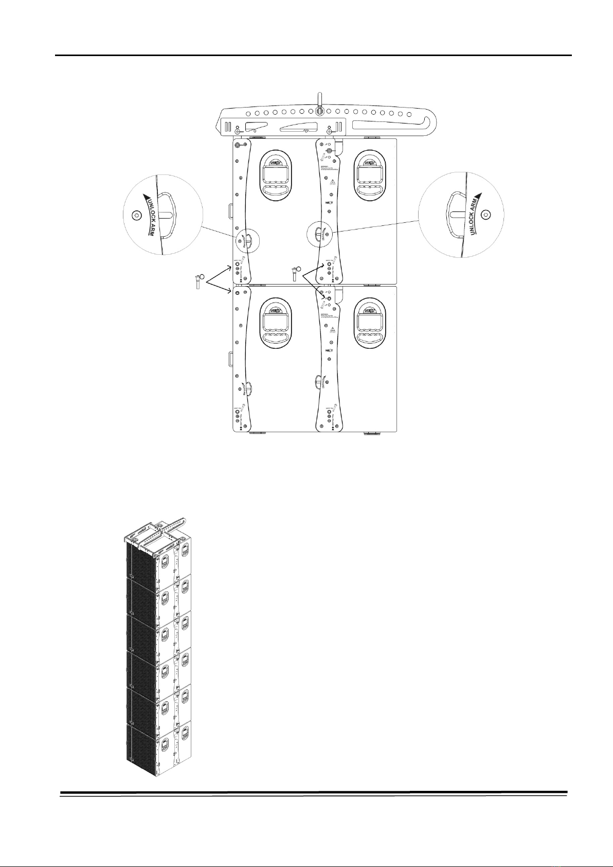
5. – With the LAs118v2 properly aligned, use the handles shown in the image to unlock the sliding arms of
the LAs118v2 on the top. By gravity, they’ll insert in the channels of the bottom LAs118v2. Insert the locking pins
as shown in the image.
6. – Repeat steps 4 and 5 for all the other enclosures and in the end
you’ll have a nice rig like this one on the left.

NEXT LAs118v2 - User Manual
www.next-proaudio.com
- 11 -
V201811
GROUND STACKING LAs118v2
Ground stacking of any loudspeaker enclosure is normally an intuitive process. But when talking about the
LAs118v2, although it is still intuitive, there are a few things to take into consideration. The first is that when packed
together like in the image above, they shouldn’t be placed touching each other. There should be a gap of at least
2 or 3 mm between vertical stacks to avoid noises due to contact induced by vibration. Another important piece of
knowledge is that when ground stacking you should not connect them using the rigging frame structures. The
locking mechanism on the sliding arms is not just to keep the arms in place. It also produces a dampening effect
on the metal parts and helps to greatly reduce vibration noises created due to the allowance on the sliding arms.
CARDIOID PATTERN SETUP
A cardioid response stack is a configuration where there is a direct
radiating element and an indirect radiating element, placed and configured
in a way that while increasing SPL in the venue, decreases it in the stage
area through destructive interference. It is becoming a very popular
configuration, because when properly configured, it almost completely
eliminates the bass at the back of the system. The development of the
LAs118v2 had this principle in mind from the beginning, and has a few
features that make it a perfect choice for this purpose. Among those, are
the universal feet that allow engagement of the LAs118v2 both in traditional
and cardioid stacks.
The preset must be adjusted to have the proper cardioid behaviour.

NEXT LAs118v2 - User Manual
www.next-proaudio.com
- 12 -
LAs118v2 and LA122v2
It has been told earlier in this manual that LAs118v2 was designed to be part of the LA122v2 system. The
purpose of this is to allow for greater versatility of both systems. They can be suspended in the same rigging frame,
and engage each other without the need of any other accessories than the locking pins. In this manual we will
focus only on the interaction between the two without going much into detail about the LA122v2. For more
information about the NEXT-proaudio LA122v2/ LA122Wv2 please consult its user manual or visit www.next-
proaudio.com.
SUSPENDING LAs118v2 with LA122v2
There have to be some considerations when rigging the LAs118v2 and
the LA122v2 together. The first and one of the most important is that the
LAs118v2 have always to be on top. For example, in a “2+4” system, you start
with the rigging procedure described in this manual for the 2 x LAs118v2 and
then continue with the rigging procedure described in the LA122v2 manual for
the 4 x LA122v2 Line Array element.
Another thing you need to know, is that between the LAs118v2 and the
LA122v2, only one splay position is possible, the 0º (in the LA122v2), due to
physical limitations in the sliding arm system of the LAs118v2. On the bottom
of the array (always after a LA122v2 enclosure) is also possible to rig the
LA122Wv2 speaker.

NEXT LAs118v2 - User Manual
www.next-proaudio.com
- 13 -
V201811
GROUND STACKING LAs118v2 with
LA122v2/LA122Wv2
The NEXT-proaudio LAs118v2 was designed to be ground
stacked with LA122(W)v2 directly, without the need of any
accessories. We can safely stack up to 4 x LA122(W)v2 on top of a
LAs118v2 provided the ground is levelled. If this is not the case,
additional measures have to be taken to secure the stack.
There are 3 splay angles between the LAs118v2 and LA122v2.
These are 4º, 0º and -4º. To make the engagement between the
LAs118v2 and LA122v2, apart from the handles already included on
the swivel arms of the LA122v2, a cut was included in the LAs118v2’s
rigging panels, so that the handle in the LA122v2 rear swivel arm is
always visible.
LAs118v2/LAs118A DOLLY
Due to allowances on wheel mechanisms, which are needed for the wheel proper functioning, loud noises
are produced when subwoofers are playing. Because of this and other factors, wheels are not included by default
on the NEXT-proaudio LAs118 v2, instead, NEXT-proaudio has developed a dolly (optional) that is used to aid in the
transportation of the LAs118v2 and LAs118A (The dolly can be used by both models). To apply the dolly simply
push it against the front grill until the “click” sound. To detach it, press the plastic pieces on the sides and pull the
dolly towards you.

NEXT LAs118v2 - User Manual
www.next-proaudio.com
- 14 -
TROUBLESHOOTING
Simple troubleshooting does not require sophisticated measurement equipment and can be easily
undertaken by users. The technique should be to segment the system in order to identify the faulty system
component: signal source, controller, amplifier, loudspeaker or cable? Most installations are multi-channel. It is
often the case that one channel works and others do not. Trying different combinations of system elements can
usually help to isolate and locate the fault.
Some cabinet faults can be quite easily identified and corrected by the user. A simple sweep with a sine
wave generator can be very helpful though it MUST be made at a fairly low level to prevent damage to the speakers.
A sine wave sweep can help find:
•Vibrations due to loose screws.
•Air-leak noises: check that no screws are missing, particularly where the accessories attach to the cabinet.
•Vibrations due to a front grille badly positioned on the quick release fixings.
•Foreign object that has fallen into the cabinet after repair or through the ports.
•Internal connection wires or absorbing material touching the loudspeaker diaphragm.
•Loudspeaker not connected or phase reversed following a previous inspection, test or repair.
WARRANTY
NEXT products are warranted, by NEXT-proaudio, against manufacturing defects in materials or
craftsmanship over a period of 5 years for the loudspeakers, and 2 years for the other components, counting from
the date of original purchase. The original receipt of purchase is mandatory for warranty validation purposes, and
the product must have been bought from a NEXT-proaudio authorized dealer. During the warranty period NEXT-
proaudio will, at its own discretion, either repair or replace a product which prove to be defective provided that the
product is returned in its original packaging, shipping prepaid, to an authorized NEXT-proaudio service agent or
distributor.
NEXT-proaudio cannot be held responsible for defects caused by unauthorized modifications, improper use,
negligence, exposure to inclement weather conditions, act of God or accident, or any use of this product that is not
in accordance with the instructions provided by this manual and/or NEXT-proaudio. NEXT-proaudio is not liable for
consequential damages. This warranty is exclusive and no other warranty is expressed or implied. This warranty
does not affect your statutory rights.

NEXT LAs118v2 - User Manual
www.next-proaudio.com
- 15 -
V201811
TECHNICAL SPECIFICATIONS
Dimensions
NEXT LAs118v2 TECHNICAL SPECIFICATIONS
Speaker Type
Passive Hybrid-Horn Subwoofer
Frequency Response (-6dB)
38Hz – 160Hz
Low Frequency Extension (-10dB)
32Hz
Calculated Max. SPL (Cont/Peak)
133.8dB / 136.8dB (Half-Space)
Components
1 x 18” / 4” Voice Coil Custom B&C Speaker
Program Power
2400W
Nominal Impedance
8Ω
Sensitivity (1W/1m)
100dB (Half-Space)
Recommended HPF
36Hz – 18dB/oct Butterworth
Recommended LPF
80Hz to 180Hz – 24dB/oct Linkwitz-Riley
Construction
18mm Multi-laminate Birch Plywood, Screwed and Glued
Finish
Black Textured Scratch Resistant Paint
Grille
Steel, Black Finish (also available in other colours)
Dimensions (W x H x D)
602 x 664 x 750 mm
Net Weight
66 kg
Shipping Weight
68.5 kg

NEXT LAs118v2 - User Manual
www.next-proaudio.com
- 16 -
NOTES
_______________________________
_______________________________
_______________________________
_______________________________
_______________________________
_______________________________
_______________________________
_______________________________
_______________________________
_______________________________
_______________________________
_______________________________
_______________________________
_______________________________
_______________________________
_______________________________
_______________________________
_______________________________
_______________________________
_______________________________
_______________________________
_______________________________
_______________________________
_______________________________

NEXT LAs118v2 - User Manual
www.next-proaudio.com
- 17 -
V201811
CONTACTS
In case of any doubts or need of information just:
Write us:
NEXT-PROAUDIO
Rua da Venda Nova, 295
4435-469 Rio-Tinto
Portugal
Contact us:
Tel. +351 22 489 00 75
Fax. +351 22 480 50 97
Send an e-mail:
info@next-proaudio.com
Search our website:
www.next-proaudio.com
Follow us on:
Facebook: facebook.com/nextproaudio
Instagram: instagram.com/nextproaudio
LinkedIn: linkedin.com/company/next-proaudio
Twitter: twitter.com/next_proaudio
Youtube: youtube.com/user/NEXTmanufacturer
Table of contents
Other Next PROAUDIO Subwoofer manuals


