Nexus 21 E-550 User manual

Installation Manual for
E-550
2
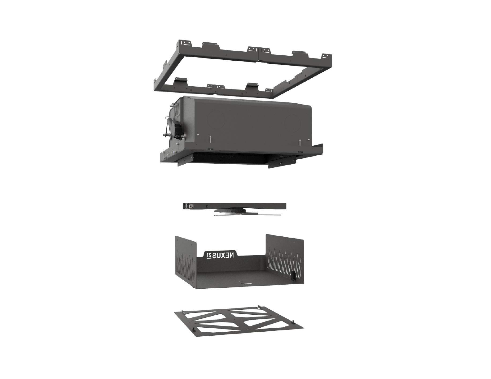
Exploded View

Table of Contents
Date:
Version: 0.0.0
00-00-00
3
Safety Information ...................................................................................................................................................................... Pg. 4
Parts List ....................................................................................................................................................................................... Pg. 5
HardwareList....................................................................................................................................................................................... Pg. 6
Warranty Information ................................................................................................................................................................ Pg. 7
Return Policy ................................................................................................................................................................................ Pg. 8
Before You Begin ........................................................................................................................................................................ Pg. 9
Installing the Actuation System ................................................................................................................................................. Pg. 12
Projector Mounting.......................................................................................................................................................................Pg.15
Ceiling Panel Attachment ............................................................................................................................................................ Pg. 20
Projector Adjustment ................................................................................................................................................................... Pg. 25
Setting a Travel Limit ................................................................................................................................................................... Pg. 28
Integration & Control Information ............................................................................................................................................. Pg. 29

Safety Information
WARNINGS:
1. Do not use this product for any application other than those specified by Nexus 21.
2. Do not exceed the weight capacity. This can result in serious personal injury or damage to the equipment. It is the installer’s responsibility to
ensure. that the total combined weight of all attached components does not exceed that of the maximum figure stated.
3. Follow all technical specifications and instructions during the installation.
4. Only use attachments/accessories specified by the manufacturer.
5. Close supervision is necessary when this system is being used by, or near, children, or disabled persons.
6. It is the responsibility of the installer to warn all potential users of the dangers of interfering with the mechanism during operation.
7. Read all technical instructions fully before installation and use. It is the installer’s responsibility to ensure that all documentation is passed on to
the users and read fully before operation.
8. Failure to provide adequate structural strengthening, prior to installation can result in serious personal injury or damage to the equipment.
9. Risk of electric shock. Do not attempt to open the Control Box.
10. To reduce risk of fire or electric shock, do not expose parts to rain or other liquids.
11 . Protect the power cord from being walked on or pinched.
12. Keep all documentation.
13. Heed all warnings.
14. Clean only with a dry cloth.
15. Refer all service questions to Nexus 21 if the system does not operate normally.
Safety Notice: You are about to suspend a heavy load above your ceiling. Please be aware that you are responsible for the construction and mounting of the frame which
will hold the lift system and the TV. You are also responsible for making sure your frame is strong enough (must be able to support at least 1000 lbs.), and that the lift system
and your frame are safely secured above your ceiling. Failure to securely mount your frame to the structure of the building, and/or failure of your frame to support the lift
system, can cause severe injury and/or property damage. If you are not qualified to perform the installation of the system, or if you are not sure if you are qualified, do not
attempt to install it. If you are not an experienced professional, please hire one to perform this installation.
Disclaimer: Nexus 21 disclaims any liability for modifications, improper installations, or installations over the specified weight range. Nexus 21 will not be liable for any
damages arising out of the use of, or inability to use, Nexus 21 products. Nexus 21 bears no responsibility for incidental or consequential damages. This includes, but is
not limited to, any labor charges for the servicing of Nexus 21 products performed by anyone other than Nexus 21. Nexus 21 intends to make this and all documentation
as accurate as possible. However, Nexus 21 makes no claim that the information contained herein covers all details, conditions or variations, nor does it provide for
every possible contingency in connection with the installation or use of this product. The information contained in this document is subject to change without prior notice
or obligation of any kind. Nexus 21 makes no representation of warranty, expressed or implied, regarding the information contained herein. Nexus 21 assumes no
responsibility for accuracy, completeness or sufficiency of the information contained in this document.
4

Parts List
E-550 Lift Mechanism Carrier Shroud Installation Bracket (Pre-Framed)
Interface Plate Universal Adjustment Bracket Universal Mounting Plate
5

Hardware List
1. Four (4) – 10-32 x 9/16” FHMS (Flat Head Machine Screw)
2. Four (4) – 10-32 x 1/2” ELHB (Extra Low Head Bolt)
3. Four (4) -- Set Screws
4. Sixteen (16) -- #8-1/2” FHWS (Flat Head Wood Screw)
5. One (1) – 1/8” T-Handle
6. One (1) -- Wrench
6

Warranty Information
Nexus 21 warrants all motorized products to be free from defects in material and workmanship for the term of the warranty. The warranty includes all parts, motorized components, electronics and metal parts. If a Nexus 21 product proves
to be defective in material or workmanship during the expressed warranty period, Nexus 21 will replace the product free of charge. If the exact original purchase product is not available (due to upgraded designs or discontinuation of a
model), the defective product will be replaced with a similar product of equal or greater value. The replacement part will then be covered by the balance of the time remaining on the customer’s original warranty.
The Nexus 21 Full Replacement Warranty does NOT cover: any product on which the serial number has been defaced, modified or removed; damage, deterioration or malfunction resulting from accident, misuse, neglect, power surges, fire,
water, lightning or other acts of nature, unauthorized product modification, failure to follow manufacturer’s recommended installation instructions supplied with the Nexus 21 product, repair or attempted repair by anyone not authorized by
Nexus 21, causes external to the product such as electric power fluctuations or failure, use of supplies or parts not meeting Nexus 21 specifications or any other cause which does not relate to a product defect.
*If the requested information cannot be provided or located on file, replacement parts may not be covered under the warranty.
Nexus 21 products are manufactured to the highest standards of quality and for that reason, we are proud to provide the
industry’s best and longest warranty:
10 years of full-replacement coverage on all motorized products.
5 years of full-replacement coverage on Apex Motorized TV Mount.
- Electrical, Water, or Fire Damage
- Improper Use or Installation of the Product Outside of Nexus 21’s Specifications
- Electrical or Collateral Damage resulting from environmental work or power outages
Step 1: Contact our support team, we will guide you through some basic troubleshooting to solve the issue remotely (via phone, video chat, or email).
Email: support@nexus21.com Phone: 480 - 306 - 5462 Video Chat: Ask your Support Specialist
~
Step 2: In the event that replacement parts are necessary to resolve your issue, our team will request the Name or Company Name of the original purchaser to initiate a
Warranty Exchange.*
Note: Our systems are specifically engineered to be simple and easy to install and service. Most of the components are plug-and-play, making any necessary replacement of parts very easy.
~
Step 3: Once the Warranty Exchange has been processed, we will arrange shipment of the part(s) and cover the shipping cost within the continental United States and Canada
(excludes HI, AK, and PR). Shipping and tracking information will be provided to you via email.
Note: International shipping costs will be covered up to a value of $50, any additional shipping costs, including Duties & Taxes, are the responsibility of the customer or receiving party.
We have a full team of dedicated support specialists ready to assist you. So should any issues arise during the use or installation of the
product follow the three easy steps listed below:
- Natural Disasters, Natural Phenomena, or other Acts of Nature
- Damage, deterioration, or malfunction resulting from accidents, misuse, or neglect
- Any other cause which does not relate to a product defect
Our warranty does not cover the following:
Disclaimer:
7

Return Policy
Nexus 21 ships each product encased in custom die-cut foam which is purpose engineered for vibration dampening to reduce any risks of shipping damage. It is mandated that all product returns be shipped back to Nexus 21 in its original packaging. If you do not have the
original packaging, please contact our Product Support team at 480-306-5462. A new set of packaging materials can be requested and the cost will be deducted from the refund amount.
From 30 to 90 Days After Delivery:
8
• The product must be unused and complete. Full or partial assembly of the product may void eligibility for return.
• The product must be returned in its original packaging to ensure it is not damaged during shipping.
• Customers must call Nexus 21 and speak with a representative to initiate a return request.
• All returns are subject to an inspection process by a member of Nexus 21 Product Support before a refund is issued.
• Please allow a minimum of 2 weeks from the date the return is received for a refund to be processed.
• Any product that is deemed unfit for restock due to installation or shipping damage will not be eligible for a refund.
• Customers are responsible for shipping charges to send the product back to us.
• All returns must be processed back to the original form of payment used in the purchase of the item(s).
Return Conditions:
Within 30 Days of Delivery:
Returns requests initiated 30 days after delivery are eligible for a full refund of the purchase price. Shipping charges associated with your order are not eligible
for refund. See return conditions above.
Returns requests initiated 30 to 90 days after delivery are not eligible for a full refund of the purchase price and will be subject to a
25% restocking fee. Shipping charges associated with your order are not eligible for refund. See return conditions above.
After 90 Days of Delivery:
Returns requests made after 90 days of the delivery date will not be accepted.
To initiate a Return follow the steps listed below:
Step 1: Call 1-888-981-9919 and request to return your product(s).
Step 2: Your Account Manager will provide you with a link to a form for you to fill out digitally.
Step 3: Arrange shipment of the product to our office. Emailing the tracking information to support@nexus21.com can expedite the process.
Once your product is received, please allow up to 2 weeks for us to inspect and process your return. You will receive a confirmation email indicating that your
return has been successfully processed. Refunds may take 5 - 10 business days depending on your issuing bank.
~
~

Before you Begin
For these steps you will need the following:
•E-550 Lift Mechanism
•Integration Cables (Not Provided)
•Audio Video Cables (Not Provided)
•Phillips Bit or Screw Driver (Not Provided)
9

10
Step 1: Connect the Power Cord for the system to an outlet located above
the Installation Bracket.
Step 2: Remove the cover shown in the image above by removing both of
the Phillips Screws, then pass all AV, Integration, and Power Cables for both
the Projector and Lift System through the Cable Tie.

11
Step 3: Cinch the cables within the terminal using the Cable Tie and re-attach the cover by sliding the back end in first, pushing the front end down, then using both
of the Phillips Screws to fasten it in place.
Note: Do not completely tighten the Cable Tie and leave about 2 ft. of length inside the E-550 Lift Mechanism to allow further cable management.
Installing the Actuation System
For these steps you will need the following:
•E-550 Housing
•(4) Fine Adjustment Screws
•T-Handle
12
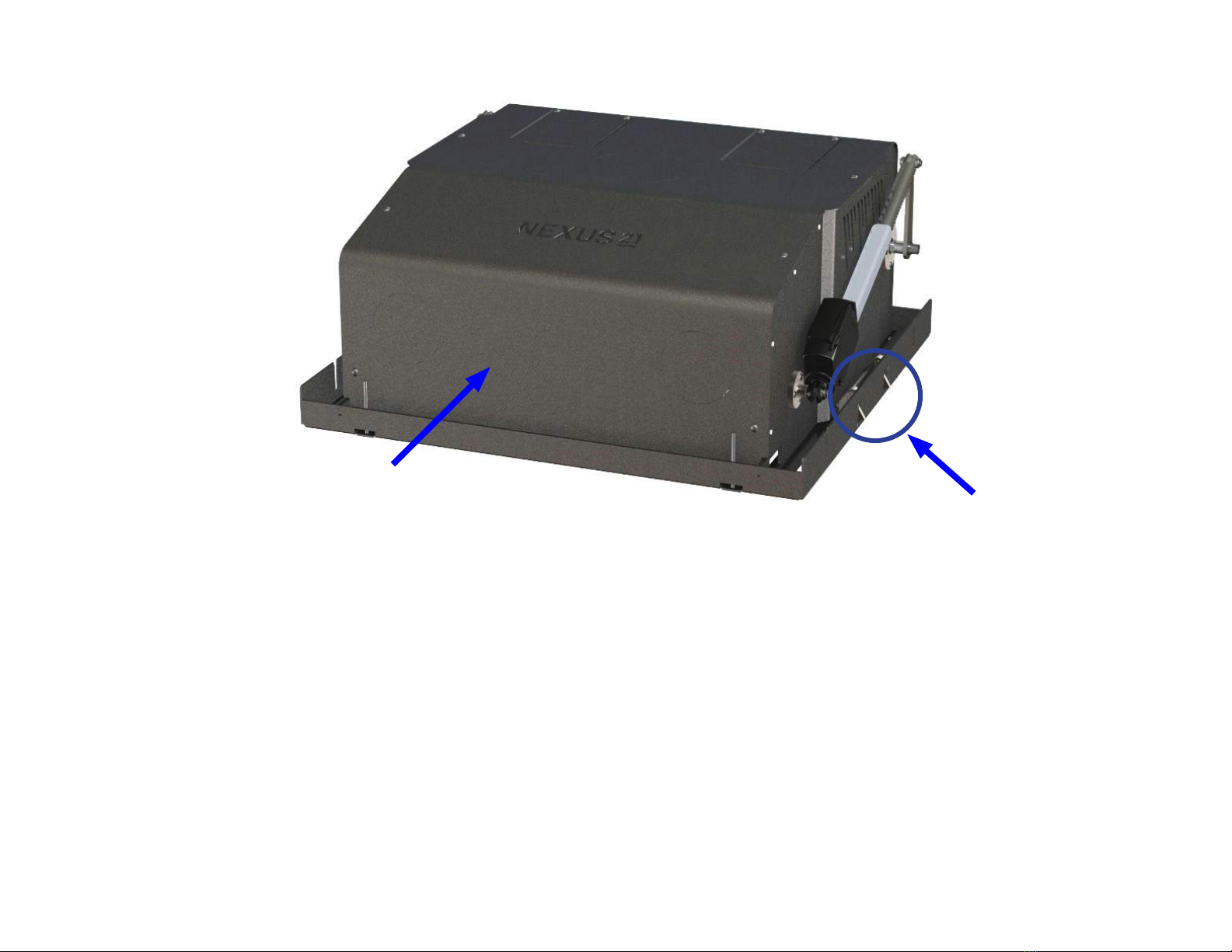
Front of System
Snap Feature

13
Step 4: Orient the E-550 Lift Mechanism so the front faces the directon you
wish to project, then lift it up to snap it into the Installation Bracket.
Important Note: Ensure the Snap Feature is fully engaged before
completely letting go of the mechanism.
Step 5: Partially fasten the (4) Fine Adjustment Screws using the provided
1/8” T-Handle.

14
Up Down
Step 6: Lower the Control Panel using the provided T-Handle to remove both of the Flat Head Screws, press the DOWN button on the Wired Backup Switch to
lower the Crossmember within the Housing, then replace the Control Panel.
Note: If you are using IR or Contact Closure, setup the Universal Remote so you can operate the system without having to lower the Control Panel.
Projector Mounting
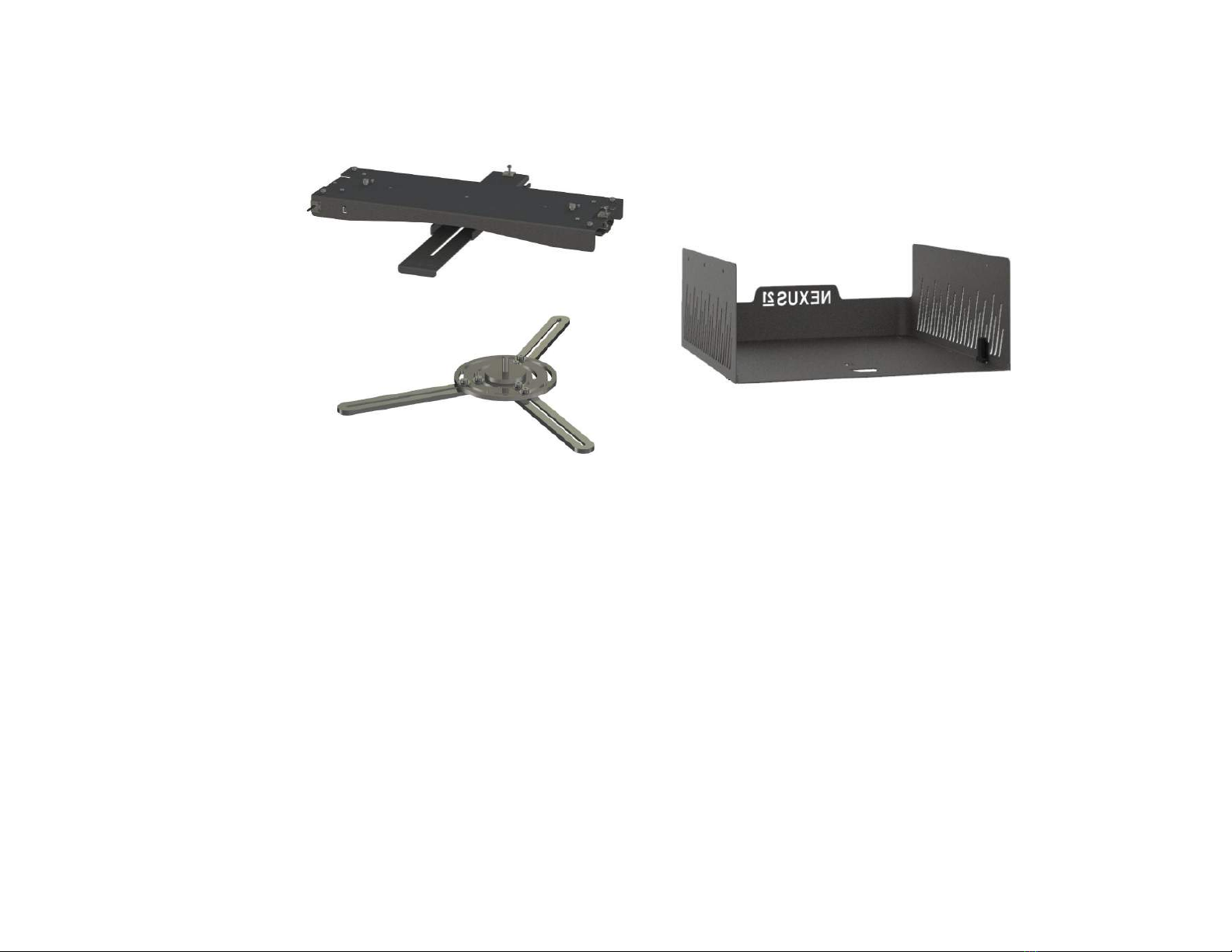
For these steps you will need the following:
•Universal Adjustment Bracket
•Universal Mounting Bracket
•Carrier Shroud
•(4) 10-32 x 9/16” FHMS Screws
•Projector (Not Provided)
•Projector Mounting Hardware (Not Provided)
•1/8” T-Handle
•Wrench
15

16
Step 7: Remove the M8 Nyloc Nut and Flat Washer from the Adjustment
Bracket, center the Mounting Bracket on the Projector and fasten it using the
required mounting hardware specified by the Projector Manufacturer.
Important Note: Due to the large variety of Projectors, we are unable
to provide the hardware required to mount the Projector to the Mounting
Bracket. Contact the Projector manufacturer or reference the User Guide for
screw sizing.
Step 8: Slide the Adjustment Bracket onto the Mounting Bracket stud so that
the front of the Projector sits behind the flange, then fasten the two together
using the previously removed M8 Nyloc Nut and Flat Washer and the
provided Wrench.
17
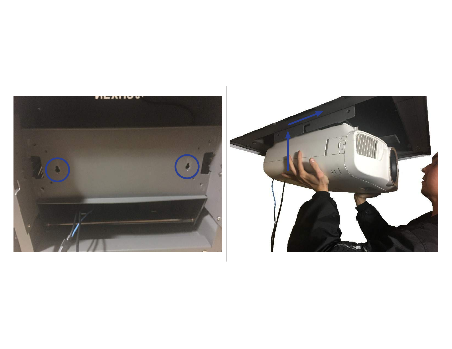
Step 9: Press the Shoulder Bolts on the Projector Mount into the keyed holes of the Crossmember, then slide it forward to lock it into place.
Important Note: Slowly let go of the Projector to make sure it is secured within the keyed holes. Once the Projector Mount is in place, do not bump or move
it until the next step is complete.

18
Step 10: Fasten the (4) Captive Hex Screws on the Projector Mount using the
provided T-Handle to secure the it to the lift mechanism.
Note: There are (2) Captive Hex Screws on the left and right of the Universal
Adjustment Bracket.
Step 11: Connect and manage any cables for integration or the projector and
feed any excess cable back up and through the Left Cable Terminal.
19
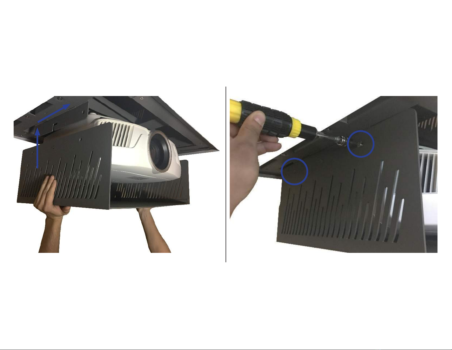
Step 12: Press and slide the Carrier Shroud up and into the L shaped slots located on the left and right side of the Crossmember then fasten it using (4) 10-32 x
9/16” FHMS Screws, (2) per side.

Ceiling Panel Attachment
For these steps you will need the following:
•Interface Plate
•Trim Ring
•Ceiling Panel
•(9) Wood Screws
•(4) Set Screws
•(4) 10-32 x 1/2” ELHB (Extra Low Head Bolt)
20
Other manuals for E-550
1
This manual suits for next models
1
Table of contents


