Nice FT210 Product manual

FT210
Optical Device
Installation instructions and warnings
Istruzioni ed avvertenze per l’installatore
Instructions et avertissements pour l'installateur
Anweisungen und Hinweise für den Installateur
Instrucciones y advertencias para el instalador
Aanwijzingen en aanbevelingen voor de installateur
Instrukcje i ostrzeżenia dla instalatora


3
GB
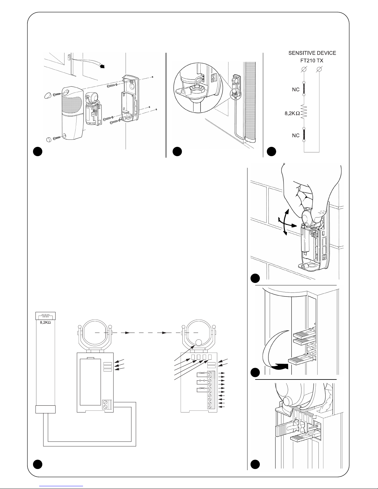
FT210 is a device that resolves the problems of electrical con-
nections of sensitive edges on the moving leaf. The device
comprises a battery powered infrared beam transmitter (TX)
that is positioned on the mobile leaf on which is connected the
sensitive edge. In addition to this is a normally powered receiv-
er (RX) which is positioned on the fixed section: 12÷24Vac/dc.
The 8,2kΩconstant resistance type sensitive edge is contin-
ually controlled by the transmitter and the activation or deac-
tivation is transmitted to the receiver. Based on the status of
the sensitive edge, the RX receiver interprets the information
received and, on the basis of the on-board status, acti-
vates/deactivates the two output relays ALT and ALT1 (also
PHOTO if jumper JP2 of receiver is deactivated See table 2).
Communication between the TX and the RX is codified by
means of high security techniques, such that the entire
device complies to the failsafe category 3 according to the
EN 954-1 standard and can therefore be used in EN 12978
standard PSPE systems.
The FT210 photocell assembled following the instruc-
tions and including the TCB65 sensitive edge, has been
certified by the manufacturer as conforming to the fol-
lowing standards:
• EN 954-1 - Machine safety - Parts of the control system
related to safety - General design principles
• EN 1760-2 - Machine safety - Pressure sensitive protection
devices - General design and test principles for pressure
sensitive edges and bars.
• EN 12978 - Industrial, commercial and garage doors and
gates. Safety devices for power operated doors and gates
- Test methods and requirements.
Warning: the FT210 does not comprise a complete safety
device but is only part of it!
The TX and RX are positioned so that the optical communi-
cation takes place through the gap (see figure 1), the device
can also be used as a presence sensor (type D according to
the EN 12453 standard). In fact, the object that interrupts the
beam deactivates the third relay of output PHOTO.
1) Warnings:
This manual contains important information regarding safety
during installation, therefore before starting installation, it is
important that you read all the information contained herein.
Store this manual in a safe place for future use.
Due to the dangers which may arise during both the installa-
tion and use of the FT210, installation must be carried out in
full respect of the laws, provisions and rules currently in force
in order to ensure maximum safety.
According to the most recent European legislation, the
automation of a door or gate is governed by the provi-
sions listed in Directive 98/37/CE (Machine Directive)
and, more specifically, to provisions: EN 13241-1 (har-
monized standard); EN 12445; EN 12453 and EN 12635,
which enable to declare the conformity of the product
to the machine directive.
Further information, risk analysis guidelines and how to draw
up the Technical Documentation is available at: www.nice-
foryou.com. This manual has been especially written for use
by qualified fitters, none of the information provided in this
manual can be considered as being of interest to end users!
• The use of FT210 which is not explicitly provided for in these
instructions is not permitted. Improper use may cause dam-
age and personal injury.
• Do not modify any components unless such action is
specified in these instructions. Operations of this kind are
likely to lead to malfunctions. NICE disclaims any liability for
damage resulting from modified products.
• FT210 must only function through TX-RX direct interpola-
tion. The use of through reflection is prohibited.
• Use suitable conductors for the electrical connections as
specified in the “installation” chapter.
• Make sure that the electrical power supply and the other
use parameters correspond to the values indicated in
“technical characteristics” table.
• The manufacture of safety devices for automatic doors and
gates is subjected to the following standards:
• EN 12453 - Industrial, commercial and garage doors
and gates. Safety in use of power operated doors -
Requirements.
• EN 12978 - Industrial, commercial and garage doors
and gates. Safety devices for power operated doors and
gates - Requirements and test methods.
The installation and connection of the FT210 as a safety
device must be performed in compliance to the said stan-
dards, if the necessary provisions are not taken, this will be
automatically considered as negligence and deliberate abuse.
Particular warnings concerning the suitable use of this prod-
uct in relation to the 89/336/EEC “Electromagnetic Compat-
ibility” Directive and subsequent modifications 92/31/EEC
and 93/68/EEC:
This product has been subjected to tests regarding the elec-
tromagnetic compatibility in the most critical of use condi-
tions, in the configurations foreseen in this instructions man-
ual and in combination with articles present in the Nice S.p.a.
product catalogue. The electromagnetic compatibility may
not be guaranteed if used in configurations or with other
products that have not been foreseen; the use of the product
is prohibited in these situations until the correspondence to
the requirements foreseen by the directive have been verified
by those performing the installation.
2) Product description and applications
1
TX
RX

4
Because the F210 photocells have a horizontal scope of 210° and a vertical scope of 30°, they can also be applied on uneven
surfaces where the correct alignment between TX and RX is not normally possible (see figure 2).
The system must be disconnected from the mains
power supply during installation. If buffer batteries are
present, these must also be disconnected.
3.1) Preliminary checks
Due to the peculiarity and uniqueness of the product, certain
aspects concerning the operating principles must be evalu-
ated before proceeding with the installation in order to ensure
maximum safety and functionality.
• Check carefully that the use parameters conform to the
data indicated in the “technical characteristics” chapter. If
in doubt, do not use the product and ask clarification from
the Nice technical assistance department.
• The transmitter continuously controls the status of the sen-
sitive edge and transmits the information to the receiver. In
order to reduce the consumption of the battery and main-
tain the required safety level, this operation is performed
with 2 different “speeds”: SLOW when the gate is at a
standstill; FAST when the gate is moving. The transmitter
detects when the gate is moving through a special sensor
that detects the vibration of the moving gate. As soon as
the gate begins to move the transmitter switches to the
FAST mode and remains so until the gate is motionless for
10 or 90 seconds (see jumpers JP2 and JP3 in table 1).
• In order to guarantee the required safety level, the receiver
must detect the status of the gate, above all to verify if the
SLOW or FAST mode of the gate is correct.
This control mechanism occurs through the “PHOTOTEST”
input of the receiver (see connection examples in figures 18
and 19). A Phototest is normally performed in the control unit
at the beginning of each manoeuvre. In this way the receiv-
er of the FT210 is informed that the gate is about to move.
• If the control unit does not have Phototest the FT210 can
in any case be used by connecting the PHOTOTEST input
of the FT210 to the SCA (Gate open indicator) output of
the control unit. In this case a flashing signal should be
present on the SCA output during the entire duration of the
movement (see the connection example in figure 20).
• If the control unit does not even have an SCA output, the
FT210 should be programmed in the continuous FAST mode
by disconnecting the JP3 jumper on the TX (see table 1).
• In the control unit in which the beginning of the opening
manoeuvre and the automatic closure is performed, the
communication from the FAST mode to the SLOW mode
must be held for 90 seconds when the gate stops (see JP2
in table 1). In this way the TX remains in the FAST mode for
the entire opening time of the gate. The pause time of the
control unit must obviously be less than 90 seconds.
• FT210 has been designed not to interfere with and not to
be interfered with by other photocells, meaning that the
FT210 can be used along with other photocells. Function-
ing is guaranteed with at least one other couple of Nice
photocells whereas functioning may not be guaranteed
with more than one couple or photocells of another make.
To check that there are no effects caused by other devices,
carefully perform the testing procedure indicated in chap-
ter 4 and check the related signals in table 5.
Two FT210 devices can in any case be placed to control
the front and rear parts of the same gate, being that the
two TX transmit the signals in the opposite direction.
• Two FT210 devices cannot be positioned to control the
same area. If a receiver receives the signal of two transmit-
ters, it activates the “safety” mode and blocks the gate
movement. See the related signal in table 5.
Figure 3 illustrates an example of correct installation.
!
3) Installation
2
3

5
GB
• The FT210 TX transmitter emits a beam with an angle of approximately ±4°, therefore a perfect alignment between TX and
RX is necessary that remains intact throughout the entire course of the gate.
Figure 4 illustrates an example of correct assembly; figure 5 illustrates two examples of incorrect assembly.
• If necessary, the receiver can be fitted on a special MOCF post with related FA2 accessories (see figure 6), or fixed to the
wall. In this case the cables can arrive from the base (see figure 7) or below, in which case it is necessary to use “PG9” type
cable clip (see figure 8).
3.2) Fixing of the devices
Perform the installation and fixing of the devices following the operations below:
1. To separate the control unit from the base, use a screwdriver to lever the three clips as indicated in fig. 9
2. Fix the receiver as shown in fig. 10.
4 5
6 7 8
910

6
3. Assemble the transmitter on the mobile leaf as shown in figure 11.
4. Connect the 8,2KΩ, constant resistance type sensitive edge on the transmitter as shown in figure 12. The resistance on the
TX terminals is removed and used as a termination on the sensitive edge or does not need to be used if the sensitive edge
already has a terminating resistance.
If the sensitive edge has an output with 2 separate NC contacts, it can be connected
as shown in figure 13 placing the 8,2KΩresistance in series between the two con-
tacts. Make sure that the sensitive edge complies with the failsafe category 3 accord-
ing to the EN 954-1 standard.
Warning: do not use sensitive edges that have only one NC type contact because
they do not have the necessary failsafe category required by the said standard.
5. Carry out the electrical connections following that which is indicated in the control
unit instructions manual. Also see the connection examples in chapter 3.3 “Electrical
connections”.
6. Direct the lenses as shown in fig. 14 in order to obtain the correct alignment
between the TX and RX. The correct alignment will be verified in chapter 4 “Testing”.
7. Program the jumpers on both the TX and RX (see figure 15) for the desired operation
following that indicated in table 1 and 2. Position the jumpers that are not used in their
locations for future use (see figures 16 and 17)
PHOTOTEST
PHOTOTEST
0Vac/dc
24Vac/dc
RXTX
L
L1
L2
L3
L4
JP1
JP2
JP1
JP2
JP3
-
+
ALT
COM
ALT1
COM
PHOTO
COM
Sensitive Device
3,6 V
11 12 13
14
16
1715

7
GB
Jumper Position Description
Connected Phototest input connected to the Phototest output of the control unit.
Phototest input connected to the S.C.A. output of the control unit; or the input Phototest
Disconnected disconnected if the control unit is not fitted with Phototest or output SCA (Caution: possible
only with JP3 on TX deactivated)
The interruption of the infrared beam causes the PHOTO contact to open.
The activation of the sensitive edge causes the ALT contact to open and the ALT1 after 1.5
seconds.
The interruption of the infrared beam causes the PHOTO contact to open.
The activation of the sensitive edge causes the ALT contact to open and the ALT1 after 1.5
seconds.
To be used in control units that do not foresee the inversion when ALT cuts in.
Disconnected
JP2
Jumper Position Description
Connected Transmitter power suitable for gates up to 15 meters.
Disconnected Transmitter power suitable for gates up to 7 meters.
Connected Change over to SLOW transmission after 10 seconds from the end of the manoeuvre
(see JP3).
Disconnected Change over to SLOW transmission after 90 seconds from the end of the manoeuvre
(see JP3).
Connected Change over to SLOW transmission at the end of the manoeuvre.
Disconnected Never changes over to SLOW transmission but remains in the FAST mode.
Table 1: TX transmitter jumpers
JP1
JP2
JP3
Table 2: RX receiver jumpers
JP1
Connected
3.3) Electrical connections
This chapter describes the electrical connections and illustrates various possible connection layouts based on the type of con-
trol unit used on the automation system. If in doubt, do not use the product and contact the Nice technical assistance depart-
ment.
Connection Cable type Max. length Description
12÷24V 2x0,5mm230m AC or DC receiver power supply
Phototest 2x0,25mm230m Start of manoeuvre test input, which can be connected to
the AC or DC voltage and is not limited by the power supply
terminals.
Output contacts 2x0,25mm230m Output relay contacts; normally closed (NC) when the receiver
is powered and active (see table 4)
Table 3: List of connections
Output Relay contact Description
PHOTO Closed There are no obstacles and the TX data is received correctly.
Open Obstacles are present and the TX data is not received.
The PHOTO output (Photocell) must be connected to the control unit input that causes the inversion of the manoeuvre,
which is normally used by the D type presence sensor.
ALT Closed No pressure is applied to the sensitive edge connected to the TX.
Open Pressure is applied to the sensitive edge connected to the TX.
The ALT output must be connected to the control unit input that causes the stop and eventual inversion of the manoeuvre,
which is normally used by PSPE pressure sensitive safety devices.
ALT1 Closed No pressure is applied to the sensitive edge connected to the TX.
Open After 1.5 seconds if pressure is applied to the sensitive edge connected to the TX.
The ALT1 output must be connected to the second input of the control unit that causes the stop and eventual inversion of the
manoeuvre, which is normally used by PSPE pressure sensitive safety devices.
In the event that this second input is not available on the control unit it is possible:
• to use the ALT1 output to control a relay of suitable capacity that directly cuts the power to the motor (see figure 18).
• not to use the ALT1 output and disconnect the JP2 on the RX, in this way when the sensitive edge is activated the PHOTO
contact is opened which also guarantees the failsafe category 3.
Table 4: RX output description

8
3.3.1) General connection example
Figure 18 shows a connection example of the
FT210 to a general control unit with PHOTO input;
ALT has a Phototest output. In this configuration,
set the RX jumpers as follows:
• JP1 connected
• JP2 activated, if activation of the ALT input of
the control unit causes shutdown and
inversion of movement (in this way the relay
connected to ALT1 in figure 18 can be
eliminated and the contact of ALT1 can be
placed in series to PHOTO and connected
to the PHOTO input of the control unit as
shown in figure 19 and 20)
deactivated, if activation of the ALT input
of the control unit causes only shutdown of
movement
M1
PHOTO
COM
ALT
COM
PHOTOTEST
PHOTOTEST
0Vac
24Vac
PHOTO
ALT
COM PHOTOTEST
24Vac
0V
230Vac
Relè con bobina a
24Vac
FT210
ALT1
COM
3.3.2) Connection example with “Pho-
totest” equipped control unit
Figure 19 shows a connection example of the
FT210 to the ROBO “RO300” model gearmotor
with the use of the Phototest function. In this con-
figuration, set the RX jumpers as follows:
• JP1 connected
• JP2 connected (control unit with inversion of
movement on activation of ALT input
PHOTO
COM
ALT
COM
ALT1
COM
PHOTOTEST
PHOTOTEST
0Vac
24Vac
FT210
FCC
FCA
PHOTO
P. P.
POWER LINE
1
2
3GND
L
N
5
4
6
7
LUX
Max 40W
COURTESY
LIGHT
11
9
8
10
12
13
PHOTOTEST
24 Vac
0 Vac
ALT
P. P.
PHOTO
3.3.3) Connection example with “SCA”
equipped control unit
Figure 20 shows a connection example of the
FT210 to the ROBO “RO1000” model gearmotor
with the use of the SCA output.
In this configuration, set the RX receiver jumpers
as follows:
• JP1 disconnected
• JP2 activated (control unit with inversion of
movement on activation of ALT input)
PHOTO
COM
ALT
COM
ALT1
COM
PHOTOTEST
PHOTOTEST
0Vac
24Vac
FT210
43
1
3
2
4
PHOTO
FCC
FCA
CH
P. P.
AP
10
7
5
6
9
8
13
12
11
41
42
44
50 Hz
220 V
LUX
PHOTO
COM
200mA
24 V ~
ALT
SCA
CH
AP
P. P.
2¯ Ch
RADIO
ANT.
18
19
20

9
GB
Each individual component of the automation system requires a specific testing phase. Perform the following sequence of oper-
ations for the testing of the FT210. The sequence is repeated for each device in the event 2 devices are present, one on the
front of the gate and one on the back of the gate (see figure 3).
Warning: some points require that the gate is in movement for the control; as the automation MAY not be adequately SAFE,
the maximum attention must be given during these controls.
1. Make sure that all that is foreseen in the present manual, in particular chapters 1 “Warnings” and 3 “Installation” is fully abided by.
2. Release and fully open the gate leaf so that the TX is at the maximum possible distance from the RX.
3. Make sure that there are no obstacles between the Tx and the RX.
4. If present, disconnect the power supply to the receiver and remove the battery from the transmitter.
5. Disconnect the sensitive device from the TX terminals and measure the resistance of the device with an ohmmeter, check-
ing that the value is between 7700Ωand 8700Ω(nominal 8200Ω).
6. Push the sensitive edge to activate it and measure once again the resistance. Check that the resistance is lower than 1000Ω
or higher than 16500Ω.
7. Reconnect the sensitive device to the TX terminals.
8. Connect the power supply to the receiver and check that the L1 (Ir Level) L2 (Phototest Ko) and L3 (Sensitive Device Ko)
LEDs are on. Check that the L4 LED (Sensitive Device Ok) is off (see figure 30).
9. Remove the JP3 jumper on the TX so that it always transmits in the FAST mode.
10. If the distance between the TX and the RX exceeds 7 m check that the JP1 jumper on the TX is connected (this meaning
programmed for distances up to 15 m).
11. Insert the FTA1 or FTA2 battery into the TX (see figure 33 or 34).
12. Check that the L1 (Ir level) LED on the RX receiver flashes; the L2 (Phototest Ko) LED and the L4 (Sensitive device Ok) LEDs
are on and that the L3 ((Sensitive device Ko) LED is off.
13. If necessary, improve the alignment by directing the TX and RX lenses as shown in figure 14. By performing the L1 (Ir lev-
el) LED signal the speed of the flashing is less and the alignment is greater. The adjustment is at its best when the LED flash-
es slowly at a maximum of 3 flashes a second.
14. Repeat the test placing the top protection covers both on TX and RX. Note that the RX cover is fitted with a damper filter
that simulates adverse weather conditions which could arise during use.
15. Move the gate leaf along the entire course and check, through the flashes of the L1 LED, that the alignment remains above
the optimum.
16. To check the optical presence sensor (type D) of
the FT210, and to make sure that there is no interfer-
ence with other devices, pass a 50 mm diameter cylin-
der across the optical axis, first near the TX, then near
the RX and finally between the two (see figure 22) and
make sure that in all cases the device is triggered,
switching from the active status to the alarm status
(LED L1 ON) and vice versa.
3.3.4) Connection of 2 or more sensitive edges
The FT210 has only one sensitive edge input, but 2 or more sensitive edges that perform the same function can be cascade
connected one after the other as in figure 21 applying a single 8.2KΩtermination resistance.
Warning: the constant resistance devices must be cascade connected and never in series or parallel to one another!
4) Testing
21
22

23
24
25
10
17. To check the PSPE pressure sensitive device of
the FT210, push and release the sensitive edge as
shown in figure 23 and check that the L4 LED turns
off and that the L3 LED turns on and vice versa.
18. If this is the preferred program, connect the JP3
jumper on the TX so that the transmission changes
over to SLOW a few seconds after the movement
has finished.
19. If the operation in the previous point has been
performed; check that the transmitter changes over
to SLOW after the foreseen time has past (see JP2
in table 1). The transmission in the SLOW mode can
be recognised through four short flashes of the L1
LED followed by a pause.
20. Mechanically connect the leaf to the motor and
perform a manoeuvre of the gate.
In the meantime, check that the L2 LED turns off at
the beginning of the manoeuvre, indicating that the
vibration sensor test of the moving gate has been
performed correctly.
21. Perform various gate manoeuvres and check
that the opening and closing are correctly performed
without the inversion of the movement.
22. Perform further manoeuvres, and during the clo-
sure activate the optical presence sensor as indicat-
ed in point 15 and check that the foreseen action is
performed such as the inversion of the movement.
23. Perform additional manoeuvres and during the
closure activate the sensitive edge as indicated in
point 16 and check that the foreseen action is per-
formed such as the inversion of the movement.
24. The control of the FT210 optical presence sen-
sor (type D), according to the EN 12445 standard, is
performed with the 700x300x200mm test paral-
lelepiped with 3 black faces and 3 polished white or
mirrored faces as indicated in figure 24 and accord-
ing to chapter 7 of the EN 12445:2000 standard (or
enclosure A of prEN12445:2005).
25. The control of the PSPE pressure sensitive
device of the FT210 according to the EN 12445
standard, is performed by measuring the force at
the points foreseen in chapter 5 of the EN 12445
standard, if the hazardous situations, which have
been caused by the movement of the leaf, have
been safeguarded through the limitation of the
impact force (type C).
26. After verifying all the above points, remove the
damper filter from the glass panel on the RX receiv-
er as shown in figure 25.
27. Make sure that all casings of the various devices
are closed when testing is complete

11
GB
5.1) Example of how the FT210 can be used as
photocell
The FT210 can be used as a simple type D pres-
ence sensor without having to connect to the sensi-
tive edge.
Figure 26 illustrates a connection example with this
type of application of the FT210 photocell device.
In this case it is necessary to:
1. Perform the assembly as indicated in the “Instal-
lation” paragraph.
2. Deactivate jumper JP3 of the transmitter to
ensure that transmission is always HIGH SPEED.
3. Use the receiver PHOTO output only
4. Connect and use the Phototest if the control unit
supports this function. In this case jumper JP1 of the
receiver must be inserted.
5. If the control unit has output SCA only, connect it to
the Phototest input of the receiver. Jumper JP1 of the
receiver must be deactivated.
6. If there is not usable output on the control unit (Pho-
totest or SCA), leave the Phototest input of the receiv-
er and deactivate the jumper JP1 of the receiver.
Note: The FAST transmission mode reduces the battery life of the transmitter. In this case the estimated life of a C type bat-
tery (FTA1 kit) is as follows:
• approximately 24 months for gates up to 7 m (JP1 jumper of the transmitter disconnected)
• approximately 18 months for gates up to 15 m (JP1 jumper of the transmitter connected)
M1
PHOTO
COM
ALT
COM
PHOTOTEST/SCA
PHOTOTEST/SCA
0Vac
24Vac
PHOTO
COM
SCA
PHOTOTEST
24Vac
0V
230Vac
FT210
ALT1
COM
5) Additional information
Personalisation and how to look for and deal with faults on the FT210 will be dealt with in this chapter.
26
5.2) Example of using FT210 only as detector of
sensitive edge detector
If FT210 is used only as detector of the sensitive
edge status, and therefore without the presence
detector function, the photocell device should be
installed as shown in figure 27.
In this case, the following is necessary:
1. Perform the assembly phase as described in the
paragraph “Installation”.
2. Connect the receiver of FT210 to the control unit
as shown in figure 28, placing the contacts PHOTO
and ALT in series.
3. Insert Jumper JP2 of the receiver.
4. Connect and use Phototest if the control unit
manages this function. In this case jumper JP1 of
the receiver and jumper JP3 of the transmitter must
be inserted.
5. If the control unit has output SCA only, connect it
to the Phototest input of the receiver. Jumper JP1 of
the receiver must be deactivated, while jumper JP3
of the transmitter must be inserted.
6. If there is not usable output on the control unit
(Phototest or SCA), do not connect anything to the
Phototest input of the receiver, deactivate the
jumper JP1 of the receiver and jumper JP3 of the
transmitter.
M1
PHOTO
COM
ALT
COM
PHOTOTEST/SCA
PHOTOTEST/SCA
0Vac
24Vac
PHOTO
ALT
COM
SCA
PHOTOTEST
24Vac
0V
230Vac
FT210
ALT1
COM
27
28

12
5.3) Example of connection of FT210 to control
unit with ALT input with constant resistance at
8.2kohm
If the control unit has an ALT input with constant
resistance of 8.2kohm , place a 8.2kohm resistance
in series with the two contacts PHOTO and ALT of
the receiver as shown in figure 29
PHOTOTEST
PHOTOTEST
0Vac/dc
24Vac/dc
PHOTO
ALT1
ALT
ALT
COM
29
5.4) Signals
The FT210 receiver has various LED signals (see figure 30)
that give luminous signals based on the operational status.
30
The sensitive edge connected to the trans-
mitter is active.
On
(ALT contact: closed)
Off
(ALT contact: closed)
LED L3 (red) Cause Action
LED L4 (green) Cause Action
LED L1 (red) Cause Action
7 short flashes
Pause
7 short flashes
Replace the transmitter battery as soon as possible
with another of the same type.
Table 5: Signals
LED L (red) Cause Action
2 short flashes
Pause
2 short flashes TX flat battery signal.
Regular flash The rate of the flash indicates the quality of
the reception: the slower the flash the
greater the reception.
Everything Ok if the flash is slow: maximum 3 per
second, otherwise the alignment of the TX and RX
must be checked.
On No signal, The “PHOTO” contact remains
open. Remove the obstacle or improve the TX and RX
alignment.
4 short flashes
Pause
4 short flashes The transmitter is in the SLOW mode. Everything Ok if the gate is not moving.
5 short flashes
Pause
5 short flashes
The receiver receives interference from
unrecognisable infrared signals.
An unknown transmitter is sending a signal towards
the receiver, try to remove the interference; check
the alignment of all devices present.
The receiver receives the signal from a sec-
ond FT210 transmitter. Eliminate the second transmitter. Two FT210 trans-
mitters cannot be positioned in the same area.
On Signals an error during the test at the
beginning of the manoeuvre and the trans-
mitter changes over to the FAST mode.
Connection or programming of the PHOTOTEST
input error. Possible poor functioning of the move-
ment sensor.
LED L2 (yellow) Cause Action
Off The test at the beginning of the last
manoeuvre was correct. Everything Ok
On
(ALT contact: open) The sensitive edge that is connected to the
transmitter is active. Check the reason the edge was activated.
The sensitive edge connected to the trans-
mitter is not active. Everything Ok
The sensitive edge connected to the trans-
mitter is not active. Everything Ok
Off
(ALT contact: open) Check the reason the edge was activated.

The gate stops during the movement or the manoeuvre is
inverted; the LED L3 (red) is on and the LED L4 (green) is off The sensitive edge has cut-in. Remove the possible obstacle
and check that the sensitive edge is working correctly.
13
GB
Symptoms Advisable checks
Table 6: Fault diagnostics
The gate cannot be controlled; all the LEDs on the FT210
receiver are off Check if the receiver is connected to the power supply by
measuring the voltage on the 12/24V terminals.
The gates starts to move but stops after 1 second; LED 2 (yel-
low) is on
The outcome of the test at the beginning of the manoeuvre was
negative and there is a possible connection or programming
error or there is a fault in the TX movement sensor of the gate.
The gate stops during the manoeuvre the manoeuvre is inver-
sed; the LED L1 (red) is constantly on. Check for possible obstacles or the alignment of the TX and
RX through the entire course of the gate.
Sometimes the gate stops during the movement or the manoeuvre
is inverted; the LED L1 (red) flashes rapidly when the gate is open.
Check the alignment between the TX and RX throughout the
entire course of the gate.
On activation of the device, the receiver has yellow led L2 lit
and red led L1 flashing. If the infrared beam is interrupted, led
L1 is permanently lit, but no relay activation is heard
The receiver is set to Phototest mode (JP1 inserted) but has
still not performed the test at the start of the manoeuvre. If the
central has the Phototest function, leave jumper JP1 of the
receiver inserted, check the connections and perform an
automation manoeuvre. If the control does not have the Pho-
totest function, the jumper JP1 must be inserted incorrectly.
Deactivate the jumper and check that the relays are activated,
interrupting the infrared beam.
Sometimes the gate stops during the movement or the manoeu-
vre is inverted; sometimes everything blocks and cannot be con-
trolled; the LED L2 (red) continues to make 2 short flashes.
The TX battery is flat and communication between the TX and
RX does not occur when conditions are poor. The flashing
LED L (red) indicates that the battery need changing.
The following accessories are available:
• FA1: metal vandal-proof casing, fitted as in figure 32
• FA2:
ixing brackets for “MOCF” posts, fitted as in figure 33
• FTA1: 3.6V battery; 7Ah type C, fitted as in figure 34
• FTA2: 3.6V battery; 2Ah type AA, fitted as in figure 35
8) Accessories
32 33 34 35
5.5) Troubleshooting
Table 6 gives possible indications on how to deal with malfunctions that may be met during installation or due to a fault.
6) Maintenance
The FT210 does not require any particular maintenance, however a control should be performed at least once every six months
to check the integrity of FT210 photocell (presence of dampness, rust, etc), cleaning of the external casing and testing as
described in chapter 4 “Testing”. The FT210 photocell has been designed to function under normal conditions for at least 10
years, therefore maintenance should be performed more frequently once this period has expired.
As in installation, also at the end of product lifetime, the disassem-
bly and scrapping operations must be performed by qualified per-
sonnel. This product is made up of different types of material, some
of which can be recycled while others must be disposed of. Seek
information on the recycling and disposal systems envisaged by the
local regulations in your area for this product category.
Caution: some parts of the product may contain pollutant or haz-
ardous substances which, if disposed of into the environment,
may cause serious damage to the environment or physical health.
As indicated by the symbol in figure 31, disposal of this product
in domestic waste is strictly prohibited. Separate the waste into
categories for disposal, according to the
methods envisaged by current legislation in
your area, or return the product to the retail-
er when purchasing a new version. Local
legislation may envisage serious fines in the
event of abusive disposal of this product.
Warning: the product operates with batteries that could contain
polluting substances and therefore should not be disposed of
along with household waste. After they have been removed from
the product (see paragraph “Battery replacement” in chapter
“FT210B installation instructions and warnings”) they should be
disposed of in compliance with the legislations locally in force.
7) Disposal
31

Useful range
14
Dimensions 46 x 128 h 45mm.
Operating temperature
Protection class casing
Assembly
Use in acid, saline or potentially explosive
atmosphere
Output relay contacts capacity
Failsafe category
1.5s ± 3%.
ALT output response time
PHOTO output response time
Directional capacity
TX transmission angle
Typical 8,2KΩ+22%/-65% for the on status (ON)
ON limits: with Rs > 2.870Ωand Rs < 10.010Ω
OFF limits: with Rs < 2.590Ωor Rs > 11.060Ω
Output relay contacts duration
9) Technical characteristics
In order to improve its products, NICE S.p.a. reserves the right to modify them at any time without prior notice. In any case, the manufacturer guar-
antees their functionality and fitness for the intended purposes. Note: all the technical characteristics refer to a temperature of 20°C.
FT210 technical characteristics
Type
Device for the optical status transmission of a constant resistance sensitive
edge positioned on the moving part, comprising a battery powered infrared
transmitter (TX) that is positioned on the moving leaf, to which is connected
the sensitive edge, and a receiver (RX) positioned on the fixed part.
Adopted technology TX-RX direct optical interpolation with modulated and coded infrared beam.
Receiver power supply 12÷24Vac/dc; limits: 10÷35 Vdc; 11÷28Vac 50/60Hz; with EN 61558 insu-
lating transformer.
Receiver absorbed current Approx. 120mA at 12Vdc; 70mA at 24Vac.
Phototest input voltage The same limits as “Receiver power supply”.
Transmitter power supply 3.6 V with type C or AA lithium battery.
Transmitter battery life
Estimated at approx. 15 years with the type C battery, 7Ah capacity; (“resi-
dential” use: TX-RX distance up to 7m; with 20 manoeuvres per day of 90”)
Estimated at approx. 5.5 years with the type C battery, 7Ah capacity;
(“industrial” use: TX-RX distance up to 15m; with 200 manoeuvres per day
of 90”)
Estimated at approx. 6 years with the type AA battery, 2Ah capacity; (“resi-
dential” use: TX-RX distance up to 7m; with 20 manoeuvres per day of 90”)
Device input range
Sensitive (Rs)
Type D presence sensor detection capacity Opaque objects located on the optical axis between TX and RX, larger than
50 mm and moving slower than 1.6m/s.
+/- 4° (value taken at 50% of the capacity).
RX reception angle +/- 3° (value taken at 50% of the capacity).
approx. 210° on the horizontal axis and 30° on the vertical axis
7 m or 15m (with JP1 inserted on TX) for maximum TX-RX misalignment ±2°
(the range may be further reduced in the presence of particularly intense
atmospheric conditions: fog, rain, snow, dust, etc.)
Maximum range (under optimum conditions) 15m or 30m (with JP1 inserted on TX) for maximum TX-RX misalignment ±
2°.
<45ms (typical 31ms).
<30ms (typical 28ms).
ALT1 output response time
3 or 2 (according to the EN 954-1 standard) according to the type of the
output connections and PHOTOTEST input
Maximum 0.5A and maximum 48Vac (resistive load: cos=1).
Mechanical life > 1.000.000 cycles; electrical > 200.000 cycles (resistive
load: 0.25A; 24Vdc).
IP44.
RX: Vertically wall mounted or on “MOCF” posts with “FA2” bracket.
TX: directly on the gate with the supplied screws.
No.
Weight Receiver 135g.
Transmitter 165 g with FTA1 or 140 g with FTA2
-20 ÷55°C.

15
GB
FT210 installation instructions and warnings
A B C
D E
These instructions can be incorporated with the “Instructions
and warnings for the use of the automation” which the
installer must give the owner of the automation, and must be
incorporated by them.
•Maintenance: Like any machine, your automation needs
regular periodic maintenance to ensure its long life and
total safety. Arrange a periodic maintenance schedule with
your installation technician. Nice recommends that mainte-
nance checks should be carried out every six months for
normal domestic use, but this interval may vary depending
on the intensity of use. Only qualified personnel are author-
ized to carry out checks, maintenance operations and
repairs.
• Do not modify the system or its programming and adjust-
ment parameters in any way, even if you feel capable of
doing it: your installation technician is responsible for the
system.
• The final test, the periodic maintenance operations and any
repairs must be documented by the person who has per-
formed them; these documents must remain under the
custody of the owner of the system
• The only recommended maintenance operations that the
user can perform periodically concern the cleaning of the
photocell glasses and the removal of leaves and debris
that may impede the automation. To prevent anyone from
activating the gate, release the automation system and use
a slightly damp cloth to clean.
• Disposal: At the end of its useful life, the automation must
be dismantled by qualified personnel, and the materials
must be recycled or disposed of in compliance with the
legislation locally in force.
• Replacement of the FT210 battery
The transmitter on the mobile leaf of the gate has a spe-
cial 3.6 V lithium battery that, depending on the use con-
ditions, has an estimated life of approximately 2 years. A
signal is given a few months before the battery is com-
pletely flat in order to give ample time for replacement.
It's time to change the battery if the receiver on the fixed
section (on the wall as in figure A or on the post as in fig-
ure B) gives the following signal: 2 short flashes followed
by a 1 second pause.
The battery is housed in the transmitter on the gate leaf; for
replacement:
1) Remove the screw caps as in figure C.
2) Unscrew the screws that hold the cover and remove it as
in figure C.
3) Use a screwdriver to leaver out the flat battery.
4) Wait about 10 seconds before introducing the new battery.
5) Make sure the polarity is correct; the plus is at the top.
6) Introduce the battery as in figure D or E depending on the
type used.
7) Secure the cover with the screws and replace the caps.
There are 2 types of battery:
• FTA1: 3.6V battery; 7Ah type C, fitted as in figure D.
• FTA2: 3.6V battery; 2Ah type AA, fitted as in figure E.
Caution: batteries used in this product are not normal
alkaline versions.
Contact Nice s.p.a. to request the spare battery kits
“FTA1” or “FTA2”.
Warning: the product operates with bat-
teries that could contain polluting sub-
stances and therefore should not be dis-
posed of along with household waste.
After they have been removed from the
product (see paragraph “Battery replace-
ment” in chapter “FT210B installation instructions and warn-
ings”) they should be disposed of in compliance with the leg-
islations locally in force.


17
I
FT210 è un dispositivo che consente di risolvere il problema
dei collegamenti elettrici di bordi sensibili posti su ante in
movimento. E' composto da un trasmettitore a raggi infraros-
si (TX), alimentato con batteria a lunga durata, che va posto
sull'anta mobile nel quale viene collegato il bordo sensibile. A
questo si aggiunge un ricevitore (RX) posto nella parte fissa
ed alimentato normalmente: 12÷24Vac/dc.
Il bordo sensibile, di tipo a resistenza costante 8,2kohm viene
verificato continuamente dal trasmettitore e lo stato di attiva-
zione o meno viene inviato al ricevitore. Il ricevitore RX interpre-
ta l'informazione ricevuta ed, in base allo stato del bordo, atti-
va o meno i 2 relè di uscita ALT e ALT1 (anche FOTO se il pon-
ticello JP2 del ricevitore è disinserito. Vedere tabella 2). La
comunicazione tra TX ed RX è codificata con tecniche ad alta
sicurezza tale che l'intero dispositivo risponde alla categoria 3
di sicurezza ai guasti secondo la norma EN 954-1 ed è quindi
utilizzabile in sistemi PSPE conformi alla norma EN 12978.
Il fotodispositivo FT210 assemblato come da istruzioni
e completo di apposito bordo sensibile TCB65, è stato
certificato dal produttore risultando conforme alle
seguenti normative:
• EN 954-1 Sicurezza del macchinario - Parti dei sistemi di
comando legate alla sicurezza - Principi generali per la
progettazione.
• EN 1760-2 Sicurezza del macchinario - Dispositivi di pro-
tezione sensibili alla pressione - Principi generali per la prog-
ettazione e la prova di bordi e barre sensibili alla pressione.
• EN 12978 - Porte e cancelli industriali, commerciali e da
garage. Dispositivi di sicurezza per porte e cancelli motor-
izzate - Requisiti e metodi di prova.
Attenzione: il solo FT210 non è un dispositivo di sicurezza
completo ma solo una parte di esso!
Se TX ed RX vengono posti in modo che la comunicazione
ottica avvenga attraverso il varco (vedi figura 1), il dispositivo
può essere utilizzato anche come rilevatore di presenza (tipo
D secondo la norma EN 12453); infatti, un oggetto che inter-
rompe il raggio provoca la disattivazione dello specifico terzo
relè di uscita FOTO.
1) Avvertenze
Questo manuale d'istruzioni contiene importanti informazioni
riguardanti la sicurezza per l'installazione, è necessario legge-
re tutte le istruzioni prima di procedere all'installazione. Con-
servare con cura questo manuale anche per utilizzi futuri.
Considerando i pericoli che si possono verificare durante l'in-
stallazione e l'uso di FT210, per la massima sicurezza è
necessario che l'installazione avvenga nel pieno rispetto di
leggi, norme e regolamenti.
Secondo la più recente legislazione europea, l'automa-
zione di una porta o cancello ricade in quanto previsto
dalla Direttiva 98/37/CE (Direttiva Macchine) e nel parti-
colare, alle norme: EN 13241-1 (norma armonizzata); EN
12445; EN 12453 ed EN 12635, che consentono di
dichiarare la conformità alla direttiva macchine.
Ulteriori informazioni, linee guida all'analisi dei rischi ed alla
realizzazione del Fascicolo Tecnico, sono disponibili su:
“www.niceforyou.com”. Il presente manuale è destinato sola-
mente al personale tecnico qualificato per l'installazione, nes-
suna altra informazione contenuta nel presente fascicolo può
essere considerata d'interesse per l'utilizzatore finale!
• L'uso di FT210 diverso da quanto previsto in queste istru-
zioni è vietato; usi impropri possono essere causa pericoli o
danni a persone e cose.
• Non eseguire modifiche su nessuna parte se non previste
nelle presenti istruzioni; operazioni di questo tipo possono
solo causare malfunzionamenti; NICE declina ogni respon-
sabilità per danni derivati da prodotti modificati.
• FT210 deve funzionare esclusivamente per interpolazione
diretta TX-RX; è vietato l'uso per riflessione.
• Per i collegamenti elettrici utilizzare conduttori adeguati
come riportato nel capitolo “installazione”.
• Accertarsi che l'alimentazione elettrica e gli altri parametri
d'utilizzo corrispondano ai valori riportati nella tabella
“caratteristiche tecniche”.
• La realizzazione di dispositivi di sicurezza per porte e can-
celli automatici è sottoposta alle seguenti normative:
• EN 12453 Porte e cancelli industriali, commerciali e da
autorimessa. Sicurezza in uso di porte motorizzate -
Requisiti.
• EN 12978 Porte e cancelli industriali, commerciali e da
garage. Dispositivi di sicurezza per porte e cancelli
motorizzate - Requisiti e metodi di prova.
L'installazione ed il collegamento di FT210 con lo scopo di
realizzare un dispositivo di sicurezza, senza soddisfare i
requisiti di queste norme, corrisponde a negligenza e delibe-
rato abuso!
Avvertenze particolari sull'idoneità all'uso di questo prodotto
in relazione alla Direttiva "Compatibilità Elettromagnetica"
89/336/CEE e successiva modifiche 92/31/CEE e
93/68/CEE:
Questo prodotto è stato sottoposto alle prove relative alla
compatibilità elettromagnetica nelle situazioni d'uso più criti-
che, nelle configurazioni previste in questo manuale di istru-
zioni ed in abbinamento con gli articoli presenti nel catalogo
prodotti di Nice S.p.a.. Potrebbe non essere garatita la com-
patibilità elettromagnetica se il prodotto è usato in configura-
zioni diverse o con altri prodotti non previsti; è vietato l'uso
del prodotto in queste situazioni finché chi esegue l'installa-
zione non abbia verificato la rispondenza ai requisiti previsti
dalla direttiva.
2) Descrizione del prodotto e destinazione d'uso
1
TX
RX

18
Con la possibilità d'orientamento di 210° sull'asse orizzontale e 30° sull'asse verticale, FT210 è utilizzabile anche dove super-
fici di fissaggio impedirebbero un corretto allineamento tra TX e RX (vedi figura 2).
Tutte le operazioni d'installazione vanno eseguite
in assenza di tensione all'impianto; nel caso sia pre-
sente la batteria tampone, è necessario scollegarla.
3.1) Verifiche preliminari
Vista la particolarità ed unicità del prodotto, prima di proce-
dere con l'installazione occorre valutare alcuni aspetti relativi
al principio di funzionamento in modo da ottenere la massi-
ma sicurezza e funzionalità.
• Verificare attentamente che i parametri di utilizzo siano
concordi con i dati riportati nel capitolo “caratteristiche tec-
niche”. In caso di dubbio non utilizzare il prodotto e
richiedere chiarimenti al servizio di assistenza tecnica di
Nice.
• Il trasmettitore verifica continuamente lo stato del bordo
sensibile ed invia l'informazione al ricevitore. Per ridurre il
consumo della batteria e mantenere comunque la sicurez-
za richiesta, questa attività viene svolta con 2 diverse
"velocità": LENTO quando il cancello è fermo; VELOCE
quando il cancello è in movimento. Il trasmettitore
riconosce lo stato di cancello in movimento attraverso uno
speciale sensore che rileva le vibrazioni del cancello in
movimento. Non appena il cancello inizia il movimento il
trasmettitore passa in modalità VELOCE e vi rimane fino a
quando il cancello rimane fermo per 10 o 90 secondi
(vedere ponticelli JP2 e JP3 in tabella 1).
• Per garantire il livello di sicurezza richiesto, il ricevitore deve
conoscere lo stato del cancello, soprattutto per verificare
se la modalità LENTO o VELOCE del trasmettitore è cor-
retta. Questo meccanismo di controllo avviene attraverso
l'ingresso "FOTOTEST" del ricevitore (vedere anche gli
esempi di collegamento in figura 18 e 19). Generalmente
nelle centrali di comando ad ogni inizio manovra, viene
eseguito un Fototest; in questo modo il ricevitore di FT210
viene informato che tra pochi istanti inizierà il movimento
del cancello.
• Se la centrale di comando non dispone di Fototest è pos-
sibile utilizzare ugualmente il dispositivo FT210 collegando
l'ingresso di FOTOTEST di FT210 alla uscita S.C.A (Spia
Cancello Aperto) della centrale; in questo caso occorre
che sull'uscita SCA sia presente un segnale intermittente
(lampeggio) durante tutta la durata della manovra (vedere
esempio di collegamento in figura 20).
• Se la centrale di comando non dispone nemmeno dell'us-
cita SCA, FT210 dovrà essere programmato in modalità
VELOCE continua disinserendo il ponticello JP3 sul TX
(vedere tabella 1).
• Nelle centrali, in cui il FOTOTEST è eseguito solo all'inizio
della manovra di apertura e c'è la richiusura automatica, è
necessaria la ritenuta di 90 secondi nella commutazione da
modalità VELOCE a LENTA alla fermata del cancello (vedere
JP2 in tabella 1). In questo modo il TX rimarrà in modalità
VELOCE per tutto il tempo di apertura del cancello. Ovvia-
mente il tempo pausa della centrale deve essere inferiore a
90 secondi.
• FT210 è stato studiato per non provocare disturbi ad altre
fotocellule e per non essere disturbato da esse; questo
significa che FT210 può essere abbinato con altre fotocel-
lule. E' garantito il funzionamento con almeno un'altra cop-
pia di fotocellule prodotte da Nice mentre potrebbe non
essere garantito il funzionamento con più di una coppia
oppure con fotocellule di altri produttori. In ogni caso, per
verificare che non vi siano influenze con altri dispositivi
eseguire scrupolosamente la procedura di collaudo pre-
vista nel capitolo 4 e verificare la specifica segnalazione in
tabella 5. Si possono comunque porre due dispositivi
FT210 per controllare la parte anteriore e posteriore di uno
stesso cancello, visto che in questo caso i due TX inviano
il segnale in due direzioni opposte.
• Non possono essere posti due dispositivi FT210 per con-
trollare la stessa area; se un ricevitore dovesse rilevare il
segnale di due trasmettitori si metterebbe nello stato di
“sicurezza” impedendo il movimento del cancello. Vedere
la specifica segnalazione in tabella 5.
Un esempio di corretta installazione è rappresentato in figura 3.
!
3) Installazione
2
3

19
I
• Il trasmettitore TX della FT210 emette un raggio con un angolo di circa ±4° è quindi necessario un perfetto allineamento tra
TX ed RX che deve rimanere costante lungo tutta la corsa del cancello.
In figura 4 è riportato un montaggio corretto; in figura 5 sono riportati due esempi di montaggio errato.
• A seconda delle necessità, il ricevitore può essere installato su apposita colonnina MOCF con lo specifico accessorio FA2
(vedere figura 6) oppure fissato a muro; in questo caso l'ingresso del cavo può avvenire dal fondo (vedere figura 7) oppure
dal basso; in questo caso è necessario aggiungere un pressacavo di tipo “PG9” (vedere figura 8).
3.2) Fissaggio dei dispositivi
Eseguire l'installazione ed il fissaggio dei dispositivi secondo la seguente sequenza di operazioni:
1. Per facilitare le operazioni di fissaggio è possibile separare la scheda elettronica dal fondo facendo leva con un cacciavite
nei tre incastri come indicato in figura 9.
2. Effettuare il fissaggio del ricevitore come indicato in figura 10.
4 5
6 7 8
910

20
3. Montare il trasmettitore sull'anta mobile come indicato in figura 11.
4. Sul trasmettitore eseguire il collegamento elettrico del bordo sensibile, di tipo a resistenza costante 8,2KΩ, come indicato in
figura 12. La resistenza presente sui morsetti del TX va rimossa ed utilizzata come terminazione del bordo sensibile oppure può
essere non usata nel caso il bordo disponga di una sua resistenza di terminazione.
Nel caso il bordo sensibile disponga di uscita con 2 contatti NC disponibili separata-
mente è possibile collegarlo come indicato in figura 13 ponendo la resistenza da
8,2KΩin serie tra i due contatti. Verificare che il costruttore del bordo sensibile dichia-
ri almeno la categoria 3 di sicurezza ai guasti secondo la norma EN 954-1.
Attenzione: non utilizzare bordi sensibili che hanno come uscita un singolo contatto
di tipo NC, non avrebbero la categoria di resistenza ai guasti richiesta dalle normative.
5. Eseguire i collegamenti elettrici secondo quanto riportato nel manuale di istruzione
della centrale di comando. Vedere anche gli esempi di collegamento nel capitolo 3.3
“Collegamenti elettrici”.
6. Orientare le lenti come indicato in figura 14 in modo da ottenere il migliore allinea-
mento possibile tra TX e RX. Il corretto allineamento verrà poi verificato nel capitolo 4
“Collaudo”.
7. Programmare i ponticelli presenti sia su TX che su RX (vedere figura 15 ) per il funzio-
namento desiderato secondo quanto indicato nelle tabelle 1 e 2. Per utilizzi futuri, ripor-
re gli eventuali ponticelli non usati nello specifico vano (vedere figure 16 e 17).
FOTOTEST
FOTOTEST
0Vac/dc
24Vac/dc
RXTX
L
L1
L2
L3
L4
JP1
JP2
JP1
JP2
JP3
-
+
ALT
COM
ALT1
COM
FOTO
COM
Sensitive Device
3,6 V
11 12 13
14
16
1715
Table of contents
Languages:
Popular Telescope manuals by other brands

Orion
Orion Observer 60mm EQ 9032 instruction manual

Saxon
Saxon 2001EQ5 instruction manual

DÖRR
DÖRR Danubia Atlas 2000 instruction manual

Meade
Meade LX200 R instruction manual

ORION TELESCOPES & BINOCULARS
ORION TELESCOPES & BINOCULARS Observer 60mm EQ instruction manual

Zeiss
Zeiss Victory DC4 Instructions for use