3. Assembly
Assembling the telescope for the first time should take about
30 minutes. You will need any tools other than the ones pro-
vided. As a general note, tighten all screws securely to elimi-
nate flexing and wobbling, but be careful not to over-tighten
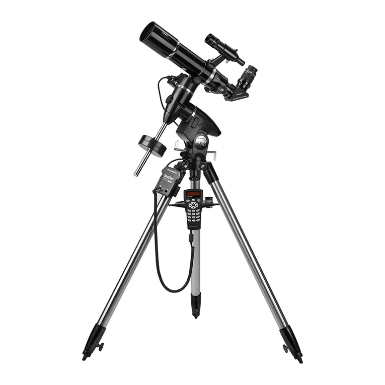
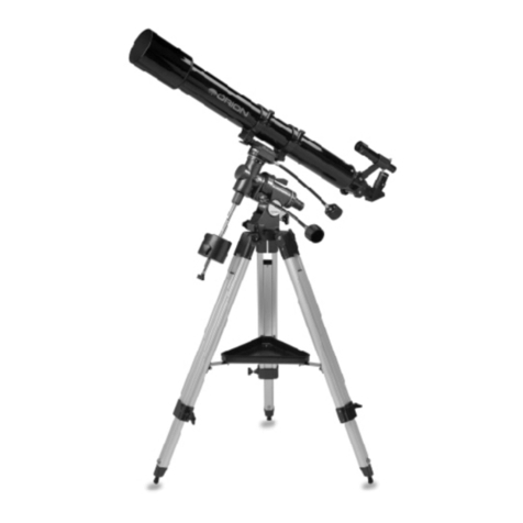
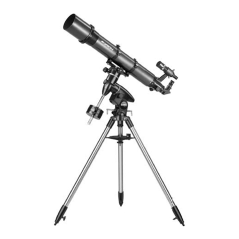
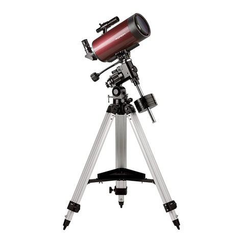
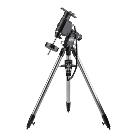
and thereby strip the threads. Refer to Figures 1 through 3
during the assembly process.
During assembly (and any other time, for that matter), do not
touch the surfaces of the telescope objective lens or the lens-
es of the finder scope and eyepiece with your fingers. These
optical surfaces have delicate coatings that can easily be
damaged if touched. Never remove any lens assembly from
its housing for any reason, or the product warranty will be
voided.
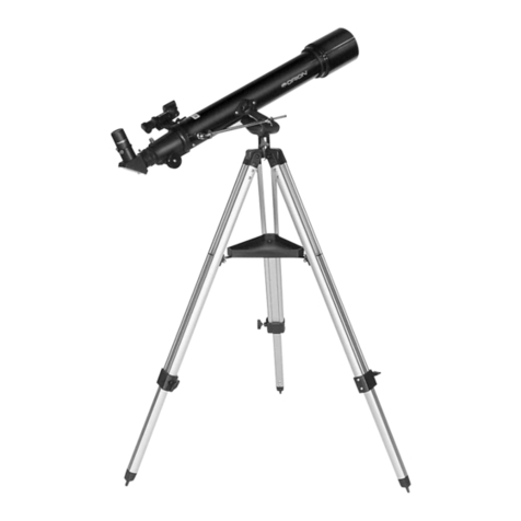
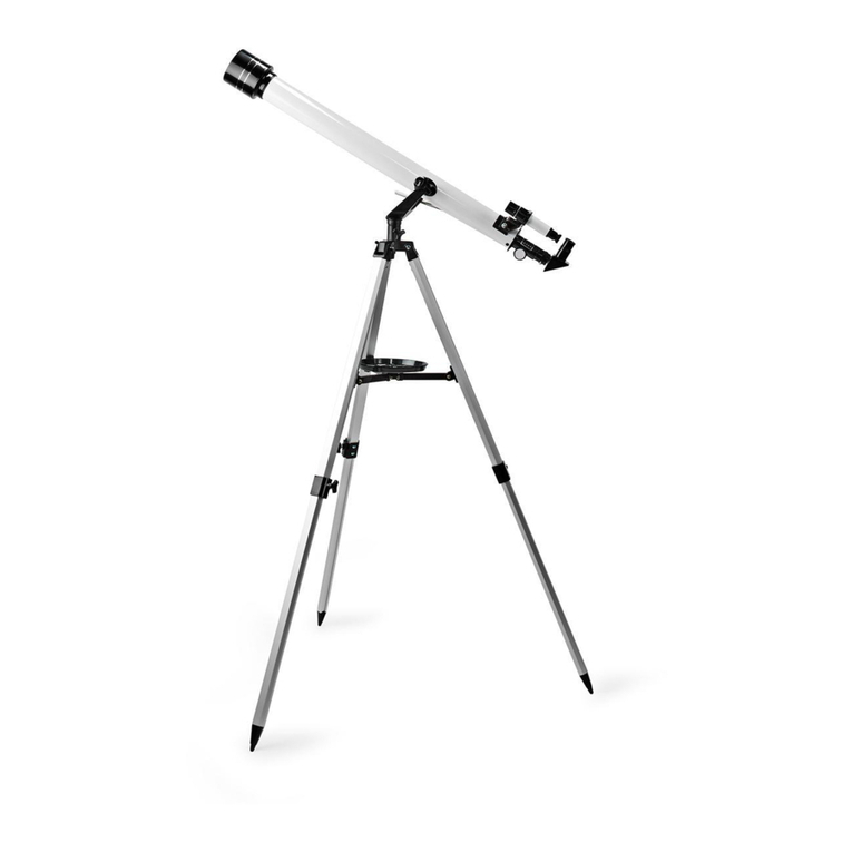
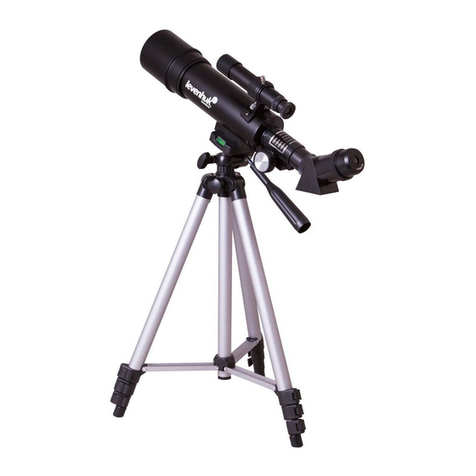
Begin set-up of the telescope by assembling the tripod and
mount first:
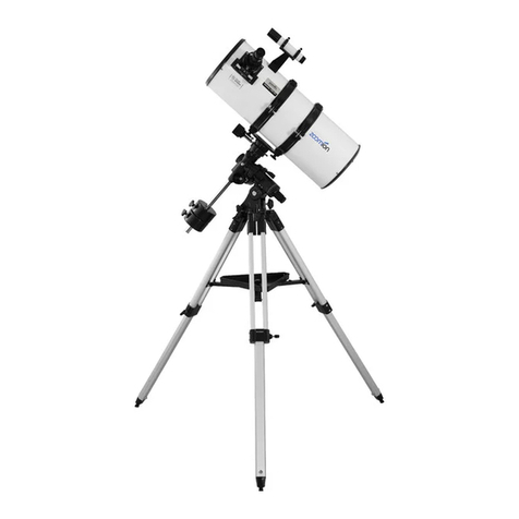
1. Lay the equatorial mount (5) on its side. Attach the tripod
legs (10), one at a time, to the base of the mount by sliding
a tripod leg attachment screw (32) through the top of a leg
and through the holes in the base of the mount. The wash-
ers should be on the outside of the tripod legs. Secure the
wing nuts finger-tight. Figure 3b shows a close-up detail of
the screws attaching the tripod legs to the mount.
2. Install and tighten the leg lock knobs (13) on the bottom
braces of the tripod legs (10). For now, keep the legs at
their shortest (fully retracted) length; you can extend them
to a more desirable length later, once the tripod is com-
pletely assembled.
3. Stand the tripod and mount upright and spread the tripod
legs (10) apart as far as they will go, until the accessory
tray bracket (12) is taut. Connect the accessory tray (11) to
the accessory tray bracket with the three wing screws
installed in the tray. Push the wing screws up through the
holes in the accessory tray bracket and thread them into
the holes in the accessory tray.
4. Tighten the tripod leg attachment screws (32) at the tops
of the tripod legs so the legs are securely fastened to the
mount. Use the Phillips head screwdriver and/or your fin-
gers to do this.
5. To install the latitude adjustment T-bolt (30), thread it into
the hole in the back of the equatorial mount (5) until tight.
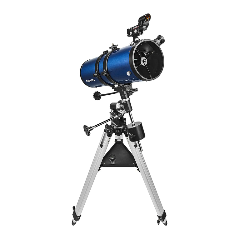
6. Orient the equatorial mount as it appears in Figure 1, at a
latitude of about 40°, i.e., so the pointer next to the latitude
scale (28) is pointing to the mark at “40.” To do this, loosen
the latitude lock T-bolt (29), and turn the latitude adjust-
ment T-bolt (30) until the pointer and the “40” line up. Then
retighten the latitude lock T-bolt. The declination (Dec.)
and right ascension (R.A.) axes may need re-positioning
(rotation) as well. Be sure to loosen the R.A. and Dec. lock
knobs (23,25) before doing this. Retighten the R.A. and
Dec. lock knobs once the equatorial mount is properly ori-
ented.
7. Thread the counterweight shaft (25) into the equatorial
mount (5) at the base of the declination axis (shown in
Figure 3a) until tight.
8. Remove the screw and washer on the bottom of the coun-
terweight shaft (26) and slide the counterweight (7) onto
the shaft. Make sure the counterweight lock knob (27) is
adequately loosened to allow the counterweight shaft to
pass through the hole. Position the counterweight about
halfway up the shaft and tighten the lock knob. Replace
the screw and washer on the end of the shaft.
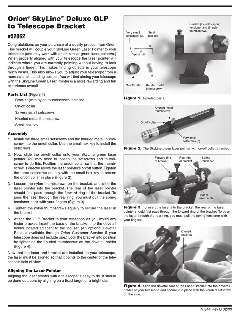
9. Open the tube rings (6) and remove them from the optical
tube (1). Unthread the hex head screws and washers from
the bottom of the tube rings. Position one of the tube rings
on the top of the equatorial mount head (16) as shown in
Figure 1. Line up the hole in the mount with the hole in the
tube ring, then push the hex head screw, with washers
attached, up through the mount and thread it into the tube
ring. Tighten the screw with the small wrench. Repeat this
for the other tube ring. Note that one of the tube rings has
a small plastic disc with a threaded shaft on it. This is for
attaching a camera and is not used for attaching the tube
rings to the mount.
10. Lay the optical tube (1) in the tube rings (6) at about the
midpoint of the tube’s length. Rotate the tube in the rings
so that the focus wheels (19) are on the underside of the
telescope. Close the rings over the tube and tighten the
knurled ring clamps finger tight to secure the telescope in
position.
10
Figure 4a-d. Proper operation of the equatorial mount requires that the telescope tube be balanced on both the R.A. and Dec. axes. (a)
With the R.A. lock lever released, slide the counterweights along the counterweight shaft until it just counterbalances the tube. (b) When you let
go with both hands, the tube should not drift up or down. (c) With the Dec. lock knob released, loosen the tube ring lock clamps a few turns
and slide the telescope forward or back in the tube rings. (d) When the tube is balanced about the Dec. axis, it will not move when you let go.
abcd
