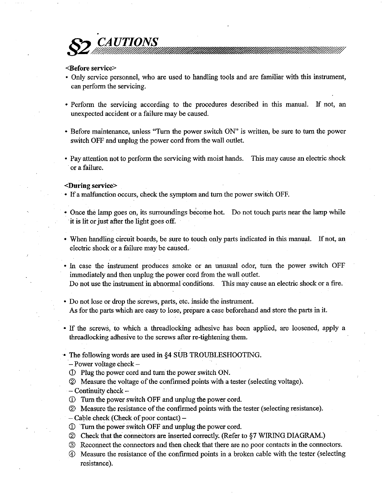
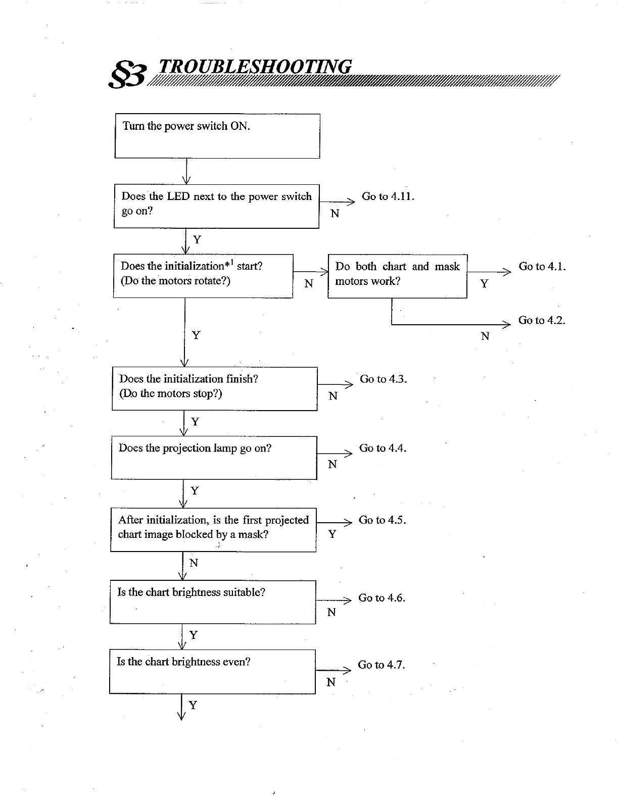
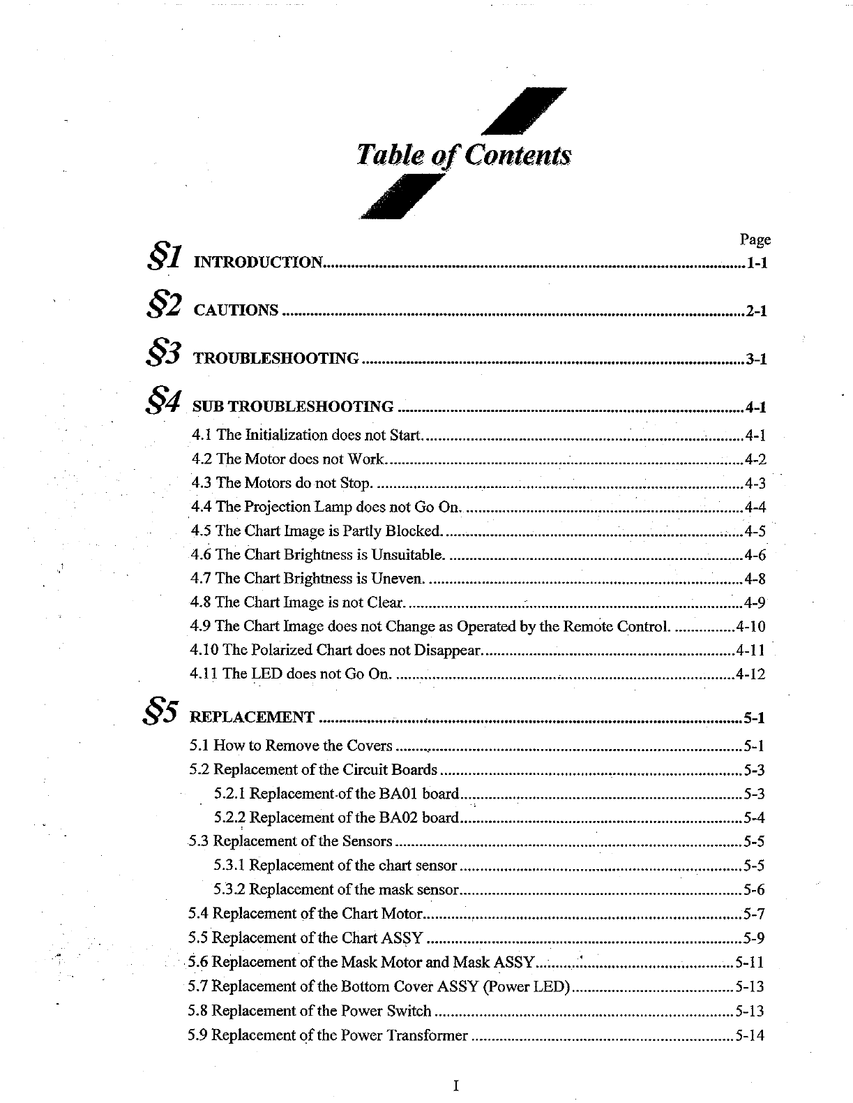
Nidek Medical CP-690 User manual

1\.
NIDEK
AUTOMATIC CHART PROJECTOR
Model CP-690
SERVICE MANUAL
D.
NIDEK
CO.,LTD.
MCP7**RDAOOlAlE
Total
Page
63

§1
§2
§3
§4
§5
I'
Table
of
Contents
I'
Page
INTRODUCTION
•••••••••....•..............................................................••..••••••••••••...••••••••.•1-1
CAUTIONS ............................•..•.•..•.•.••••••...••...•••••••.••....•...•.................•.......................•2-1
TROUBLESHOOTING
...............•.......•..•.•..•..•.•.••....•......••••.••....•.......••.........•..•.••.......3-1
SUB
TROUBLESHOOTING
..........................................•.........••••..••.••••••••••••••••••••••.••4-1
4.1 The Initialization does not Start......................................................................•.........4-1
4.2 The Motor does notWork.........................................................................................4-2
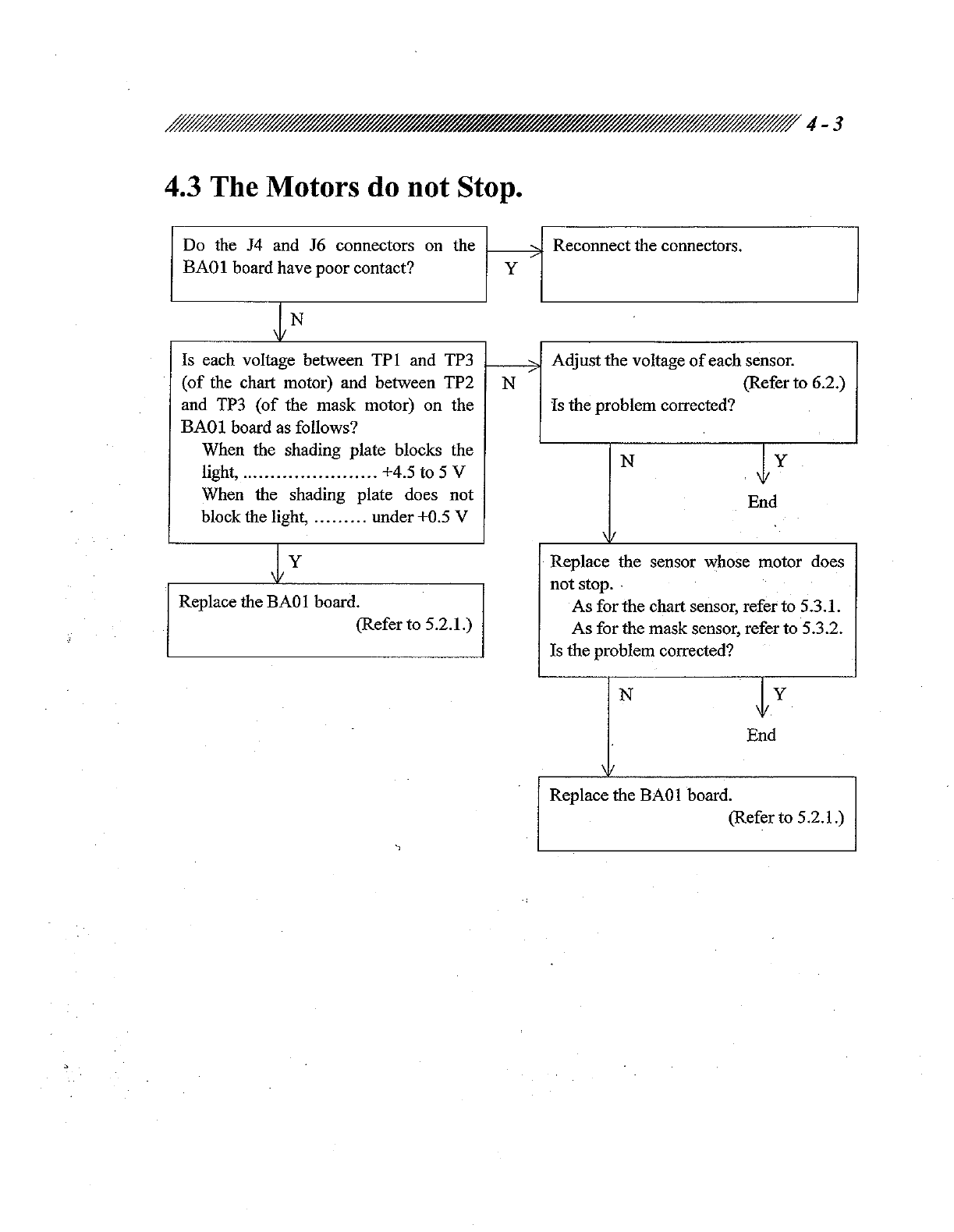
4.3 The Motors do not Stop............................................................................................4-3
4.4 The Projection Lamp does not Go On......................................................................4-4
4.5 The Chart Image is Partly Blocked.....................................................................•.....4-5
4.6 The Chart Brightness is Unsuitable..........................................................................4-6
4.7 The Chart Brightness is Uneven...............................................................................4-8
4.8 The Chart Image is not Clear..............................
~
.....................................................4-9
4.9 The Chart Image does not Change as Operated
by
the Remote Control. ...............4-10
4.10 The Polarized Chart does notDisappear...............................................................4-11
4.11 The LED does not Go On.........................................•...........................................4-12
REPLACEMENT
.........................................................................................................5-1
5.1
Howto Remove the Covers ........,.............................................................................
5-1
5.2 Replacement
of
the Circuit Boards...........................................................................5-3
5.2.1 Replacement-ofthe BAOI board......................................................................5-3
5.2.2 Replacement
of
the BA02 board......................................................................5-4
5.3 Replacement
of
the Sensors......................................................................................5-5
5.3.1 Replacement
of
the chart sensor......................................................................5-5
5.3.2 Replacement
of
the mask sensor......................................................................5-6
5.4 Replacement
of
the Chart Motor............•..................................................................5-7
5.5 Replacement
of
the
ChartAS~Y
..............................................................................5-9
5.6 Replacement
of
the MaskMotorand MaskASSY...........:.....................................5-11
5.7 Replacement
of
the Bottom Cover ASSY (power LED)........................................5-13
5.8 Replacement
of
the Power Switch ..........................................................................5-13
5.9 Replacement
of
the Power Transformer .................................................................5-14
I

Page
5.10
R~placement
of
the C lens ASSY, Lamp Cable and Reflecting Mirror ...............5-15
5.11
Replacement
of
the Holder ASSY ........................................................................5-17
5.12 Replacement
of
the Halogen Lamp.......................................................................5-18
5.13 Replacement
of
the Fuses .....................................................................................5-18
5.14 Cleaning ................................................................................................................5-19
5.14.1 Cleaning
of
the chart and mask....................................................................5-19
5.14.2 Cleaning
of
the halogen lamp, reflecting mirror and condenser lens ..........5-20
5.14.3 Cleaning
of
the holder ASSY ......................................................................5-21
§6
ADJUSTEMENT .....••.....................................................................•••••••••••...................6-1
6.1
Adjustment
of
the Initialized Position......................................................................
6-1
6.2 Adjustment
of
the Sensor Voltage............................................................................6-2
6.3 Adjustment
of
the Lamp FilamentPosition................;...;.........................................6-3
6.4 Adjustment
of
the Fixed MaskPosition....................................................•...............6-4
6.5 Adjustment
of
the Chart and MaskPositions ...........................................................6-5
6.6 Setting..............................:........................................................................................6-6
6.6.1 Setting
of
the voltage sensor............................................................................6-6
6.6.2 To display
or
not display the visual acuity......................................................6-7
6.6.3 Selecting the amount
of
chart light..................................................................6-8
6.6.4 Setting
of
the beep sound volume (Response sound) ......................................6-8
6.6.5 Setting
of
the DIP switch.................................................................................6-9
§7
INFORMATION..................................................................:.••••.••.....................•.••.......7-1
§8
§9
7.1
Wiring Diagram .............................................
'"
........................................................
7-1
7.2 How to Carry Outthe Wiring .................................................................•.................7-5
LIST OF REPLACEABLE PARTS ...................................••••••....................••••••••••....8-1
TOOLS AND MEASURINGDEVICES .................................•••••••••.••••••.•.............••••9-1
II

R-,
INTRODUCTION
:Y1.
This service manual provides information for after-sales service
of
the NIDEK Automatic Chart
Projector Model CP-690.
For proper after-sales service, it
is
necessary to understand this manual thoroughly before
servicing.
Refer to "CP-690 Operator's manual".
Specifications are subject to change without notice for improvement. As for important changes,
refer to Technical Bulletins;
In
case the instrument cannot be repaired by procedures described in this manual, please tell us
the serial number
ofthe
instrument and details
of
the symptom or symptoms.

R,.., CAUTIONS
:y~.
<Before service>
• Only service personnel, who are used to handling tools and are familiar with this instrument,
can perform the servicing.
• Perform the servicing according to the procedures described in this manual.
If
not, an
unexpected accident or a failure may be caused.
• Before maintenance, unless "Turn the power switch ON" is written, be sure to tum the power
switch OFF and unplug the power cord from the wall outlet.
• Pay attention notto perform the servicing with moist hands. This may cause an electric shock
or a failure.
<During
service>
•
If
a malfunction occurs, check the symptom and
tum
the power switCh
OFF.
• Once the lamp goes on, its surroundings become hot. Do not touch parts near the lamp while
it is litor
just
after the light goes off.
• When handling circuit boards,
be
sure to touch only parts indicated in this manual.
If
not,
an
electric shock ora failure may be caused.
• In case the ·instrument produces smoke or an unusual odor, turn the power switch OFF
immediately and then unplug the power cord from the wall outlet.
Do not use the instrument in abnormal conditions. This may cause an electric shock or a fire.
• Do notlose or drop the screws, parts, etc. inside the instrument.
As for the parts which are easy to lose, prepare a case beforehand and store the parts in it.
•
If
the screws, to which a threadlocking adhesive has been applied, are loosened, apply a
threadlocking adhesive to the screws after re-tightening them.
• The following words are used in §4 SUB TROUBLESHOOTING.
-Power voltage check-
CD
Plug the power cord and
turn
the
power
switch ON.
@ Measure the voltage
of
the confirmed points with a tester (selecting voltage).
-Continuity check -
CD
Tum the power switch OFF and unplug the power cord.
@ Measure the resistance
of
the confirmed points with the tester (selecting resistance).
-Cable check (Check
of
poor contact) -
CD
Turn
the power switch OFF and unplug the powercord.
@ Check thatthe connectors are inserted correctly. (Refer to §7 WIRINGDIAGRAM.)
@ Reconnect the connectors and then check that there are no poor contacts in the connectors.
@ Measure the resistance
of
the confirmed points in a broken cable with the tester (selecting
resistance).

.
§3
TROUBLESHOOTING
•
Tum the power switch ON.
J
Does
the
LED next to the power switch
00
to 4.11.
goon?
""/
N
Jy
Does the initialization*1 start? Do both chart and mask
00
to 4.1.
(Do the motors rotate?) N
""/
motors work? y
I ,
00
to 4.2.
y N
Does the initialization finish? ,
00
to 4.3.
(D.o
the motors stop?) N -
Jy
Does the projection lamp go on?
00
to 4.4.
N---
Y
,I,
After initialization,
is
the first projected ,
00
to 4.5.
chart image blocked by a mask? Y
0'
N
\
Is
the chart brightuess suitable?
00
to 4.6.
"0
N
Y
Is
the chart brightness even?
00
to 4.7.
---
N
1y

.3-2
lY
Is the chart image clear?
Go
to 4.8.
N
ly
Does the chart image change as operated , Go to 4.9.
by the remote control? N
~Y
Are there any charts blocked by the
mask? Y
IN
Does the charttilt againstthe mask? Make fine adjustments
of
the chart
Y and mask ASSYs.
~N
(Refer to 6.5.)
When looking at the polarized chart , Go to 4.10.
with polarizing glasses, does the chart N
image disappear?
~Y
Is the volume
of
the beep sound , Adjust the volume
of
the beep sound
(response sound) appropriate? N (response sound).
~Y
(Refer to 6.6.4.)
End
*1 The initialization performs the following operations.
1) The chart ASSY rotates and then stops bythe sensor.
2) The chart ASSY moves little by little to correct its position.
3) The maskASSY rotates and then stops bythe sensor.
4) The mask ASSY moves little by little to correct its pqsition.
5) The projectionlamp goes on. The first chart is presented.

§4
SUB TROUBLESHOOTING
•
4.1 The Initialization does not Start.
Are the fuses blown? Replace the fuses.
y/ (Referto 5.13.)
IN
Is the working voltage
±!
0 %
of
the Use another wall outlet or a voltage
rating voltage? N regulator.
ly
Is the setting
of
the voltage selector N .Set the voltage selector again.
correct? (Refer to 6.6.1.)
ly
.
Does the power cord have continuity? , Replace the power cord.
N
JY
Does the power switch have continuity? Replace the power switch.
(Before checking the continuity, unplug N / (Refer to 5.8.)
the power cord from the wall outlet and
tum
the power switch ON and OFF.)
(Refer to 7.1.)
ly
Is the voltage between the 1st and 3rd , Replace the transformer.
pins
of
the
PI
connector AC 15.6 V N (Referto 5.9.)
±5 %? (Before measuring the voltage,
disconnect the
P!
connector from the
circuit board.)
ly
.
Replace the
BAO!
board.
(Refer to 5.2.1.)

.4-2
4.2 The Motor does not Work.
When interchanging the connector , Replace the BAOI board.
positions
of
the chart and mask motors, y (Refer
to
5.2.1.)
does the working motor change?
IN
Replace the motor that does not work.
As for the chartmotor, refer to 5.4.
As for the mask motor, refer to 5.6.

.4-3
4.3 The Motors do not Stop.
Do the J4 and J6 connectors on the Reconnect the connectors.
BAOl board have poor contact? Y
~N
Is each voltage between TP1 and
TP3
Adjust the voltage
of
each sensor.
(of
the chart motor) and between TP2 N (Referto 6.2.)
and
TP3
(of
the mask motor) on the Is the problem corrected?
BAOl board as follows?
When the shading plate blocks the N
~Y
light,
.......................
+4.5 to 5 V
When the shading plate does not End
block the light,
.........
under +0.5 V
ly
Replace the sensor whose motor does
not stop
..
Replace the
BAO
1board. As for the chart sensor, refer to 5.3.1.
(Refer to 5.2.1.) As for the mask sensor, refer to 5.3.2.
Is the problem corrected?
N
~Y
End
\11
Replace the
BAOI
board.
(Refer to 5.2.1.)
~

.4-4
4.4 The Projection Lamp does not Go On.
Is
the filament
of
the halogen lamp , Replace the halogen lamp.
broken? y (Refer to 5.12.)
IN
Is
the voltage between the 1st and 2nd , Replace the
BAOI
board.
pins
of
the J2 connector over DC 5 V? N (Refer to 5.2.1.)
(when the setting
of
SW2 is channel 2)
ly
Does EA04 (CABLE LAMP) have Replace EA04 (LAMP CABLE).
continuity? N (Refer to 5.10.)
ly
Replace the
BAOI
board.(Refer to 5.2.1)

·4-5
4.5 The Chart Image is Partly Blocked.
Is the blocked part on the right side
of
Move the
VA
mask toward the inside
of
the visual acuity indication
or
chart? N the instrument (mask motor side).
ly
(Refer to 6.6.2.)
Are the motors, chart ASSY and mask Adjust the chart and maskpositions.
ASSY fixed securely?
N'
(Refer to 6.5.)
ly
Adjust the initializedposition.
/'
(Refer to 6.1.)
1
Does the mask (disk) block the chart? Adjustthe sensor voltage.
N (Refer to 6.2.)
ly
Does the fixed mask block the chart? , Adjust the chart and maskpositions.
N'
(Refer to 6.5.)
ly
~
Adjust the'position
of
the fixed mask. Adjustthe initialized position.
(Refer to 6.4.) (Refer to 6.1.)
l
Adjust the sensor voltage. (Refer to 6.2.)
.

·4-6
4.6 The Chart Brightness is Unsuitable.
Is the setting
of
the light control switch Set the light control switch to the
N /
(SW2 on the
BAOI
board) appropriate? appropriate channel.
[This switch has five channels; from 1 (Refer to 6.6.3.)
(most bright) to 5 (darkest).]
*The setting at shipment is "2".
~
Y
Is the setting
of
the voltage selector N Reset the voltage selector.
appropriate? (Refer to 6.6.1.)
li
.
Is the working voltage ±10 %
of
the , Use another wall outlet or
a,
voltage
rating voltage? N / regulator.
ty
The halogen lamp is the rated one (6
V,
Replace the halogen lamp.
20W)?
N (Refer to 5.12.)
ly
Is the halogen lamp dirty? Clean the halogen lamp.
y (Refer to 5.14.2.)
N
Is the reflecting mirror dirty? Clean the reflecting mirror.
y (Referto 5.14.2.)
N
Does the aluminum coating on the Replace the reflecting mirror.
reflecting mirror come off? Y / (Refer to 5.10.)
N
I
Is the aluminum coating deposited on Clean the condenser lens.
the condenser lens? y (Refer to 5.14.2.)
N
~

.4-7
Is
there any dust on the chart ASSY? Clean the chart ASSY.
Y , (Refer to 5.14.1.)
N
II
.
Is there any dust inside the lens barrel? Clean the projection lens inside the lens
y / barrel. (Refer to 5.14.3.)
N
\
Is the polarized chart dark? Is the polarizing filter burht? (is it
Y , brown?)
. N
,!,
Y
N Replace
1:\1e
chartASSY.
(Referto 5.5.)
\11
Is the voltage between the 1st and 2nd
~
pins
of
the J2 connector over DC 5
V?
Replace the transformer.
(when the setting
ofSW2
is channel 2) N (Refer to 5.9.)
\ Y
IReplace the screen.

.4-8
4.7 The Chart Brightness is Uneven.
Does the unevenness show up
in
the
~
Clean the chart
ASSY.
same area
of
the chart? N (Refer to 5.14.1.)
\ Y
Is
the C lens ASSY dirty, burnt or , Clean the C lens ASSY.
N /
scratched? (Refer to 5.14.2.)
If
the dirt or burnt area can not be
Y cleaned, or the ASSY
is
scratched,
replace it. (Refer to 5.10.)
Is
the holder ASSY dirty, burnt or Clean the holderASSY.
scratched? N (Refer to 5.14.3.)
If
the dirt or burnt area can not be
Y cleaned, or the ASSY is scratched,
replace it. (Refer to 5.11.)
\
Adjust the position
of
the lamp filament. , End
Is the chart brightness still uneven? N
(Referto 6.3.)
Y
Replace the screen.

.4-9
4.8 The Chart Image is not Clear.
Adjust the focus
of
the chart.· Is the End
image still not clear? N
(As for the adjustment method, refer to
the operator's manual.)
y
\
Clean the chart ASSY. Is the image , End
stilI
not
clear? N
(Refer to 5.14.1.)
y
Clean the holder
ASSY.
Is the image End
still not clear? N
(Refer to 5.14.3.)
\1
Replace the screen.

.4-10
4.9 The Chart Image does not Change as Operated by
the Remote Control.
Are the batteries
in
the remote control Replace the batteries with new ones.
drained? y /
N
\11
Does the chart image change normally Install the instrument apart from
y /
by
cutting the interference light off? windows or spot lights.
N
The settings
of
the remote control and , Make the settings for using several CP-
main body (channel
of
the remote y 690 units.
~eferto
6.6.5.)
control}are correct?
Is the voltage between the 1st pin
of
the Replace the BAOI board.
J7
connector and TP3 DC 5 V ±5
%?
N (Refer to 5.2.1.)
y
Do the points below have continuity? Replace the BA02 board.
BA01
board
BA02
board N (Refer to 5.2.2.)
J7
P7
1st
pin
B 1st
pin
2nd
pin
B 2nd
pin
3rd
pin
B
3rd
pin
y
\
Replace the remote control.
..

.4-11
4.10 The Polarized Chart does not Disappear.
Is the main body tilted? Install the main body
on
a stable and
y level surface.
N
Is the projected charttilted?
~
Adjust the initialized position.
y
~
(Referto 6.1.)
N
Is the refractor used to polarize the , Replace the chartASSY.
chart? y (Refer to 5.5.)
N
Is the trial lens used to polarize the Does the polarized chart
chart? Y / image disappear
by
moving N
the lens?
N
Jy
End
\
Are the polarizing glasses used to Does the view change by
polarize the chart? y reversing the right and left N
of
the glasses?
y
\
Replace the polarizing glasses.

.4-12
4.11 The LED does not Go On.
Is the voltage between the 1st and 2nd , Replace the
BAOI
board.
pins
of
J9 on the
BAOI
board +4.5 to 5 N
~
(Refer
to
5.2.1.)
V?
(Before measuring the voltage, remove
the P9 connector from the board.)
~Y
Replace the bottom cover ASSY
(including the powerLED).
(Refer to 5.7.)

§:.
~"l:
REPLACEMENT
~.
5.1 How to Remove the Covers
[NOTE]Before removing the covers, unless
"Tum
the power switch ON" is written, be sure to
tum
the power switch OFF and unplug the power cord.
[NOTE]Once the lamp goes on, its surroundings become hot. Do not touch parts near the lamp
until they cool down.
[How
to
remove
the
top
cover
ASSy]
Rotate the fastener a half-tum with a coin.
Remove the top cover ASSY by lifting the
rear side
of
itup.
[How to
remove
the
front
cover
ASSy]
L Remove the top coverASSY.
- _ 2
2. Unscrew PT3 x
10
and remove the front
cover ASSY together with the plate (M074).
*When remounting this part, be careful
of
theorientation
of
the plate (M074). (See the
right figure.)
[How
to
remove
the
bottom
cover
ASSy]
1.
Remove the top cover ASSY.
2. Disconnect the connector from J9
on
the
BAOI board.
3. Unscrew BS3 x 6
zn
c2 to remove the
hook
(MOSS).
4. Unscrew BS3 x
6z
nc2 and PC3 x
10c/
to
remove the bottom cover.
*When the lens barrel obstructs the removal, -
shorten itto the minimum.
PT3x
10'
Other manuals for CP-690
1
Table of contents
Other Nidek Medical Projector manuals