Nippon Denon AVR-600 User manual

D
a
N
©
3
Hi-Fi
AV
Surround
Receiver
SERVICE
MANUAL
MODEL
AVR-600/6GOORD
AV
SURROUND
RECEIVER
cto
By
pesto
TEXT
PRO
LOGIC
|
—)
Se
DED
©
CHO
<>
of
Sb
badsoe
O
OO
(Model:
AVA-600RD)
—
TABLE
OF
CONTENTS
—
OPERATING
INSTRUCTIONS...
EXPLODED
VIEW
WIRE
ARRANGEMENT
PARTS
LIST
OF
EXPLODED
VIEW
DISASSEMBLY
a
ADDENDUM
PARTS
LIST
CONNECTION
DIAGRAM
OF
MEASURING
INSTRUMENTS
...
BLOCK
DIAGRAM
SEMICONDUCTORS...
ahaphadisasabvdgesateccadieegd
staat
12~
WIRING
DIAGRAM
NOTE
FOR
PARTS
LIST
REMOTE
CONTROL
UNIT
(RC-195)
PARTS
LIST
OF
P.W.BOARD
..
SCHEMATIC
DIAGRAM
PRINTED
WIRING
BOARD
|
@
Some
illustration
using
in
this
service
manual
is
slightly
different
from
the
actual
set.
|
NIPPON
COLUMBIA
CO.
LTD.

©
SAFETY
PRECAUTIONS
CAUTION
CAUTION:
TO
REDUCE
THE
RISK
OF
ELECTRIC
SHOCK,
DO
NOT
REMOVE
COVER
(OR
BACK).
NO
USER-SERVICE-
ABLE
PARTS
INSIDE.
REFER
SERVICING
TO
QUALIFIED
SERVICE
PERSONNEL
‘the
lightning
flash
with
arrowhead
symbol,
with-
in
an
equilateral
triangle.
is
intended
to
alert
the
user
to
the
presence
of
uninsulated
“dangerous
voltage”
within
the
product's
enclosure
that
may
be
of
sufficient
magnitude
to
constitute
a
risk
of
electric
shock
to
persons
The
exclamation
point
within
an
equilateral
triangle
is
intended
to
alert
the
user
to
the
pres-
A
ence
of
important
operating
and
maintenance
(servicing)
instructions
in
the
literature
accompa-
nying
the
appliance.
;
TO
REDUCE
THE
RISK
OF
FIRE
OR
ELECTRIC
SHOCK,
DO
NOT
EXPOSE
THIS
APPLIANCE
TO
RAIN
OR
MOISTURE.
1
PREVENT
ELECTAIC
SHOCK
DO
NOT
USE
THIS
(POLARIZED)
PLUG
WITH
AN
EXTENSION
CORD,
RECEPTACLE
OR
OTHER
OUTLET
UNLESS
THE
BLADES
CAN
BE
FULLY
INSERTED
TO
PREVENT
BLADE
EXPOSURE.
POUR
PREVENIA
LES
CHOCS
ELECTRIQUES
NE
PAS
UTILISER
CETTE
FICHE
POLARISEE
AVEC
UN
PROLONGATEUR
UNE
PRISE
OE
COURANT
OU
UNE
AUTRE
SORTIE
DE
COURANT,
SAUF
SI
LES
LAMES
PEUVENT
£TRE
INSEREES
A
FOND
SANS
EN
LAISSER
AUCUNE
PARTIE
A
DECOUV-
ERT.
NOTE
ON
USE
/
OBSERVATIONS
RELATIVES
A
L'UTILISATION
Keep
the
set
tree
from
moisture,
water,
and
dust
©
Do
not
let
foreign
objects
in
the
set.
©
Ne
pas
laisser
des
objets
dvrangers
dans
Vappareil
Proveger
|'apparei!
contre
humidité,
l'eau
@
=
Avand
high
temperatures
Alow
for
sufficent
heat
dispersion
when
installed
on
8
rack.
Eviter
des
temperatures
élevees
Tena
compte
d'une
dspersion
de
chaleur
sutfisante
lors
de
Finstaliation
sur
une
éta-
gare.
‘Unplug
the
power
cord
when
not
using
ihe
‘sat
for
long
periods
of
time.
Debrancher
le
cordon
d'slimentation
lors-
que
l'appared
n'est
pas
utilisé
pendant
de
et
la
poussiere
Do
not
let
insecuicides,
benzene,
and
thin-
Net
come
in
contact
with
the
sat.
Ne
pas
mattre
en
contact
des
insecticides.
du
benzane
et
un
chiuvant
avec
l'appareil.
Handle
the
power
cond
carefully.
Hold
the
plug
when
unplugging
the
cord.
Moempuier
ia
cordon
d'alimentation
avec
Précaunon.
Tenis
la
prse
lors
du
debranchemant
du
cordon
i
“(For
sets
with
ventilation
holes)
Never
disassemble
or
modify
the
setin
any
"{Pou
des
appareils
avec
des
ouvertures
déération)
©
Co
not
obstruct
the
ventilation
holes
@
Ne
pas
obstruar
les
trous
d'aération.
way.
Ne
jamas
démonter
ou
modifier
l'appareil
d'une
manera
ou
d'une
autre.
10.
VW.
SAFETY
INSTRUCTIONS
Read
Instructions
-
All
the
safety
and
operating
instruc-
tions
should
be
read
before
the
appliance
is
operated.
Retain
Instructions
~
The
safety
and
operating
instruc-
tions
should
be
retained
for
future
reference.
Heed
Warnings
-
Ail
warnings
on
the
appliance
and
in
the
operating
instructions
should
be
adhered
to.
Follow
Instructions
—
All
operating
and
use
instructions
should
be
followed.
Water
and
Moisture
—
The
appliance
should
not
be
used
near
water
-
for
example,
near
a
bathtub,
washbowl,
kitchen
sink,
laundry
tub,
in
a
wet
basement,
or
near
a
swimming
pool,
and
the
like.
Carts
and
Stands
~
The
appliance
should
be
used
only
with
a
cart
or
stand
that
is
recommended
by
the
manufacturer.
An
appliance
and
cart
combination
should
be
moved
with
care.
=
Quick
stops,
exces-
e
is.
|
sive
force,
and
uneven
surfaces
may
cause
»
\
the
appliance
and
cart
Ia
=
combination
to
overturn
—o
Walt
or
Ceiling
Mounting
-
The
appliance
should
be
mounted
to
a
wall
or
ceiling
only
as
recommended
by
the
manufacturer.
Ventilation
-
The
appliance
should
be
situated
so
that
its
location
or
position
does
not
interfere
with
its
proper
ven-
tilation,
For
example,
the
appliance
should
not
be
si-
tuated
on
a
bed,
sofa,
rug,
or
similar
surface
that
may
block
the
ventilation
openings;
of,
placed
in
a
built-in
installation,
such
as a
bookcase
or
cabinet
that
may
im-
pede
the
flow
of
air
through
the
ventilation
openings.
Heat
-
The
appliance
should
be
situated
away
from
heat
sources
such
as
radiators,
heat
registers,
stoves,
or
other
appliances
{including
amplifiers)
that
produce
heat.
Power
Sources
—
The
appliance
should
be
connected
to
8
power
supply
only
of
the
type
described
in
the
operat-
ing
instructions
or
as
marked
on
the
appliance.
Grounding
or
Polarization
-
Precautions
should
be
taken
$o
that
the
grounding
or
polarization
means
of
an
ap-
pliance
is
not
defeated.
CHARGE
UNIT
IEC
SECTION
810-201
GROUNDING
CONDUCTORS
(NEC
SECTION
610-21),
GROUND
CLAMPS
POWER
SERVICE
GROUNDING
ELECTRODE
SYSTEM
ONEC
ART
280,
PART
+
NEC
-
NATIONAL
ELECTRICAL
CODE.
12.
14,
18.
16.
17.
20.
Power-Cord
Protection
-
Power-supply
cords
should
be
routed
so
that
they
are
not
likely
to
be
watked
on
or
pinched
by
items
placed
upon
or
against
them,
paying
particular
attention
to
cords
at
plugs,
conveniance
recep-
tacles,
and
the
point
where
they
exit
from
the
appliance.
Cleaning
-
The
appliance
should
be
cleaned
onty
as
rec-
ommended
by
the
manufacturer.
Power
Lines
-
An
outdoor
antenna
should
be
located
away
from
power
lines.
Outdoor
Antenna
Grounding
-
{f
an
outside
antenna
is
connected
to
the
receiver,
be
sure
the
antenna
system
is
grounded
so
as
to
provide
some
protection
against
voltage
surges
and
built-up
static
charges.
Article
810
of
the
National
Electrical
Code,
ANSI/NFPA
70,
provides
in-
formation
with
regard
to
proper
grounding
of
the
mast
and
supporting
structure,
grounding
of
the
lead-in
wire
to
an
antenna-discharge
unit,
size
of
grounding
conduc-
tors,
location
of
antenna-discharge
unit,
connection
to
grounding
electrodes,
and
requirements
for
the
ground-
ing
electrode.
See
Figure
A.
Nonuse
Periods
-
The
power
cord
of
the
appliance
should
be
unplugged
from
the
outlet
when
left
unused
for
along
period
of
time.
Object
and
Liquid
Entry
-
Care
should
be
taken
so
that
ob-
jects
do
not
fall
and
liquids
are
not
spilled
into
the
encio-
sure
through
openings.
Damage
Requiring
Service
-
The
appliance
should
be
serviced
by
qualified
service
personnel
when:
A.
The
power-supply
cord
or
the
plug
has
been
dam-
aged;
or
8.
Objects
have
fallen,
or
tiquid
has
been
spilled
into
the
appliance;
or
Cc.
The
appliance
has
been
exposed
to
rain;
or
0.
The
appliance
does
not
appear
to
operate
normally
or
exhibits
a
marked
change
in
performance;
or
€.
The
appliance
has
been
dropped,
or
the
enclosure
damaged.
Servicing
—
The
user
should
not
attempt
to
service
the
ap-
pliance
beyond
that
described
in
the
operating
instruc-
tions.
All
other
servicing
should
be
referred
to
qualified
service
personnel.
SNOILONYLSNI
ONILVYAdO
2
EE
er
CIOOS/IOS
Ay
se

@
We
greatly
appreciate
your
purchase
of
the
AVR-600.
@
Jo
be
sure
you
take
maximum
advantage
of
all
the
features
the
AVR-G00
has
to
offer,
read
these
instructions
carefully
and
use the
set
properly,
Be
sure
to
keep
this
manual
for
future
refarance
should
any
questions
or
problems
arise
“SERIAL
NO.
PLEASE
RECORD
UNIT
SERIAL
NUMBER
ATTACHED
TO
THE
REAR
OF
THE
CABINET
FOR
FUTURE
REFERENCE”
TABLE
OF
CONTENTS
a
Introduction
......
4
4-6
Recording
the
program
source
.....
..0..202.
10
|
2}
Connections
4-7
Front
panel
display
--.
10
2-1
Connecting
the
audio
components
oi
eS
a8
Using
the
suncund
function
...
10~12
2-2
Speaker
system
connections”
6
[5]
Listening
to
the
radio
2-3
Connecting
the
video
components
...
...............
6
5-1
Auto
preset
memory
12
2-4
Connecting
the
antenna
terminals
:..................
7
5-2
Auto
tuning
rf
12
3]
Remote
Control
Unit
......
0...
eee
ihe
inte
708
5-3
Manualtuning
...2..
0...
eee
eee
13
14]
Operations
5-4
Preset
memory
........
Bed
tints
wae
Rae
gee
VS
[4]
i
aitiseee
ons
for:
playback
8
5-5
Recalling
preset
stations
................
0...
...
13
\~
ee
r . .
f
4-2
Playing
the
program
source
[6]
Initialization
of
the
Microprocessor
....
.....
°
etal
dS
(Stereo
playback)
.
.
9
7}
Last
function
memory
at
:
14
4-3
Simulcast
playback
9
(8)
Troubleshooting
.
. :
rate
14
4-4
Using
the
muting
function
9
[s|
Specitications
Fey ena
na ee
aa
415
4-5
Listen
with
headphones
9
@
ACCESSORIES
Check
that
the
following
parts
are
included
in
addition
to
the
main
unit:
@®
Operating
instructions
..
. “
a1
@
Warranty
:
as
3 :
1
®
Remote
control
unit
(RC-198}
oe
ee
wd
@®
RGP/AA
batteries
.
whoa
sere
pate
7)
®
AMloopantenna
......
waded Manse
eRe
Saad
®
FMindoor
antenna
..........
[1]
INTRODUCTION
e@
INSTALLATION
PRECAUTIONS
Using
this
receiver
or
other
electronic
equipment
containing
micropro-
Cessors
simultaneously
with
a
tuner
or
TV
may
result
in
noise
in
the
sound
OF
picture
If
this
should
happen,
take
the
following
steps
@
‘Install
the
receiver
as
far
as
possibie
from
the
tuner
or
TV
set.
@
Keep
the
antenna
lines
of
the
tuner
or
TV
as
far
as
possible
from
the
receiver's
power
cord
and
connection
cables
©
This
problem
is
especially
frequent
when
using
indoor
antennas.
*
10.
cm
oF
more
We
recommend
using
outdoor
antennas
and
75
Q/ohms
coaxial
ene
roe
cables
Watt
For
heat
dispersal,
leave
at
feast
10
cm
of
space
between
the
top,
back
and
sides
of
this
unit
and
the
wall
or
other
components.
Za
CAUTION:
Whenever
the
power
switch
is in
the
STANDBY
position.
the
unit
is
stilt
connected
on
AC
tine
voltage.
Please
be
sure
to
unplug
the
cord
when
you
leave
home
for,
Say,
a
vacation
[2]
CONNECTIONS
Do
not
plug
in
the
power
cord
until
all
connections
have
been
completed.
Be
sure
to
connect
the
left
and
right
channets
properly
(left
with
left,
right
with
right).
Insert
the
plugs
securely.
Incomplete
connections
will
result
in
the
generation
of
noise.
Use
the
AC
OUTLETS
for
audio
equipment
only.
Do
not
use
then
for
hair
driers,
atc,
Note
that
binding
pin
plug
cords
together
with
power
cords
or
placing
them
near
a
power
transformer
wilt
result
in
the
introduc-
tion
of
hum
or
other
noise.
!f
hum
or
other noise
is
produced
when
the
ground
wire
is
con-
nected,
disconnect
it.
Noise
or
humming
may
be
generated
if
a
connected
component
is
used
independently
without
turning
the
power
of
the
AVR-600
on.
if
this
happens,
turn
on
the
power
of
the
AVR-600.
2-1
Connecting
the
audio
components
NOTE:
The
soceiver
cannot
be
used
win
MC
cantidges
ditectly
Use
a
separaie
head
ampktier
oF
step-up
transtormer
©
Precautions
when
cannecting
speakers
HW
@
apeaker
is
pleced
near
TV
oF
video
momtor,
the
colors
on
tha
screen
may
de
disturbed
by
the
spesker's
magnetism
if
this
should
happen,
move
the
speaker
away
to
3
position
where
it
does
not
heve
thes
effect
LINE
OUT
Turntable
(MM
cartridge)
Main
speaker
A
(Fron
=
Cr,
[OO
Connection
jack
for
sub-wooler
with
buitt-in
amptifier
(super
woofen,
etc
LINE
OUT
\
|
fit}
th.
aoe
Main
speaker
8
Center
speaker
(Front)
©
SWITCHED
{total
capacity
-
120W
1A.)
‘The
power
to
this
outlet
is
turned
on
and
off
in
conjunction
with
the
POWER
switch
on
the
AVA-600,
and
when
the
pow-
ers
switched
between
on
and
standby
trom
tha
remote
con-
trol
umit.
No
power
is
supplied
fron
these
outlets
when
the
AVR-600's
power
is
at
stendby,
Never
connect
equipment
whose
total
capacity
is
above
120W
(1A)
NOTE:
Only
use
the
AC
outlets
for
audio
equibment.
Never
use
them
for
hair
driers,
TVs
or
other
electrical
appkances.
5
BES
SOO
S/S
Ay
a

2-2
Speaker
System
Connections
@
This
receiver
can
accommodate
connections
of
a
total
of
seven
speakers
including
two
set
of
(front)
main
speakers
(A
and
B},
one
set
of
rear
speakers,
and
one
center
speaker.
Connect
the
speaker
terminats
with
the
speakers
making
sure
that
bike
polarities
ara
matched
(@
with
@,
©
with
O).
Mismatching
of
polarities
will
rasult
in
weak
central
sound,
unclear
orientation
of
the
various
instruments,
and
the
sense
of
direction
of
the
stereo
being
impaired.
When
making
connections,
take
care
that
none
of
the
individual
con-
ductors
of
the
spesker
cord
come
in
contact
with
sdjacent
termi-
nals,
with
other
speaker
cord
conductors,
of
with
the
rear
panel.
©
Speaker
impedance
When
speaker
systems
A
and
8
are
use
separately,
speakers
with
an
impedance
of
from
6
to
16
2/ohms
can
be
connected.
Be
careful
when
using
two
pairs
of
in
speakers
{A
+
B)
at
the
same
time,
since
use
of
speakers
with
an
impedance
outside
the
range
of
12
to
16
Q/ohms
will
lead
to
damage.
Speakers
with
an
impedance
of
8
to
16
Q/ohms
can
be
con-
nected
for
use
as
center
and
rear
speakers.
The
protection
circuit
may
operate
of
damage
may
occur
when
speakers
with
an
impedance
outside
of
the
above
range
are
used.
Connecting
the
speaker
terminals
1.
Loosen
by
turning
2.
Insert
the
cord.
3.
Tighten
by
turning
counterclockwise.
rl
clockwise.
“>
@B
2.
Insert
the
cord.
2-3
Connecting
the
video
components
To
connect
the
video
signal,
connect
using
a
75
Q/ohms
video
signa!
¢able
cord.
Using
an
improper
cable
can
result
in
a
drop
in
sound
quality.
Connecting
banana
plugs
Banana
plug
SS
3.
Return
the
lever.
Tusn
clockwise
to
tighten,
then
insert
the
banana
plug.
AUDIO
OUT
VIDEO
OUT
»
eencunanne
TEATS
b
S
AUDIO
IN
LD
player,
COV
player,
TV,
etc.
Monitor
TV
2-4
Connecting
the
antenna
terminals
ANTENNA
INSTALLATION
©
Fd
ANTENNA
The
supplied
FM
antenna
canbe
used
inside
wooden houses
for
recewing
local
FM
stahons
and
other
sisong
FM
signals
Stretch
out
the
ends
of
the
antenna
and
mount
the
antenna
on
the
wall
oF
ceiling
where
optimum
tecapuon
us
achweved
Aindoor
FM
antennas
may
not
Consisienity
ensue
stable
18-
ception,
due
to
environment
changes.
in
such
cases,
the
in-
door
FM
antenna
should
only
be
used
temporarity
unui
an
out
door
FM
antenna
has
been
installed
When
connecting
an
outdoor
FM
antenna,
the
use
of
75
Q/ohms
coms!
cable
(3C~2V,
SC-2V}
is
strongly
recom
mended.
©
AM
ANTENNA
Tune
in
en
AM
station
treler
to
Page
12, 13)
ksten
to
the
Sound,
then
install
the
antenna
in
a
position
as
tar
from
the
set
a5
possible
wn
whuch
distortion
End
Noise
are
minimum
Good
Feception
of
AM
stanons
is
not
possible
if
the
loop
antenna
is
Rot
connected
oF
if
it
is
touching
metal
objects
NOTES
FM
tadoor
antenna
©
This
receiver
has
@
{ull
back-up
system.
When
the
power
is
[An
Accessory)
chasiat
cable
turnad
on,
the
INPUT
SELECTOR
butions
are
sei
to
the
tast
mode
sat
before
the
power
was
turned
olf,
©
When
using
this
receiver
in
close
proxilruty
10
vidleo
equip:
ment
(TV,
VCR,
VDP,
etc),
noise
may
be
generated
in
AM
broadcasts
To
avord
this,
keep
the
receiver
as
tat
away
from
other
video
components
a3
possible,
or
place
ine
AM
oop
antenna
where
noise
1s
seduced.
If
the
nowe
is
not
reduced,
turn
off
the
power
of
the
video
components
when
listening
10
AM
broadcasts.
Connection
of
AM
antennas
1.
Push
the
fever.
2.
Insert
the
conductor.
3.
Return
the
lever.
Note
to
CATV
system
Instatior:
Tivs
‘eminder
1s
provided
to
call
the
CATV
system
installer’s
attention
to
Article
820-40
of
the
NEC
which
provides
guide-
lines
for
proper
grounding
and,
in
particule,
specihes
that
the
cable
ground
shalt
be
connected
to
the
grounding
system
of
tha
‘budding,
as
close
to
the
pomt
of
cable
entry
as
precuicat
[3]
REMOTE
CONTROL
UNIT
Following
the
procedure
outlined
below,
insert
the
batteries
before
using
the
remote
contro!
unit.
@
Range
of
operation
of
the
remote
control
unit
Point
the
remote
control
unit
at
the
remote
control
sensor
as
shown
on
the
diagram
at
the
left.
NOTES:
©
The
remote
control
unit
can
be
used
from
a
straight
distance
of
approximately
7
meters/20
feet,
but
this
distance
will
shorten
or
op-
eration
will
become
difficult
if
there
are
obstacles
between
the
re-
mote
control
unit
and
the
remote
control
sensor,
if
the
remote
con-
‘sol
sensor
is
exposed
to
direct
sunlight
or
other
strong
light,
or
if
operated
from
an
angle.
©
Neon
signs
or
other
devices
emitting
pulse-type
noise
nearby
may
Approx.
2rrv20
feet
result
in
malfunction,
so
keep
the
set
as
far
away
from
such
devices
as
possible.
@
Inserting
the
batteries
1,
Open
the
bottom
cover
of
the
remote
control
unit
|
2.
Insert
the
two
R6P/AA
batteries,
match-
|
3.
Close
the
bottom
cover
until
it
and
remove
the
battery
cover.
ing
the
©
and
©
marks
on
the
batteries
clicks
shut.
with
those
in
the
case.
€8
NOTES:
Use
only
AA,
R6P,
UM-3
batteries
for
replacernent.
Be
sure
the
polarities
are
correct.
(See
the
illustration
inside
the
battery
compartment.)
Remove
the
batteries
if
the
remote
contro!
transmitter
will
not
be
used
for
an
extended
period
of
time.
If
batteries
teak,
dispose
of
them
immediately.
Avoid
touching
the
leaked
material
or
letting
it
come
in
contact
with
clothing,
etc.
Clean
the
battery
compartment
thoraughly
before
installing
new
batteries.
Have
replacement
batteries
on
hand
so
that
the
old
batteries
can
be
replaced
as
quickly
as
possible
when
the
time
comes.
A
EE
TH
HOOS/OOS-HAW
mae

@
System
code
buttons
DENON
remote-controllable
audio
components
can
be
controlled
using
this
unit's
remote
control
unit
Note
that
some
components.
however,
cannot
be
operated
with
this
remote
control
unit.
©
Setthe
slide
switch
to
the
position
for
the
compo-
nent
to
be
operated
(CD
or
DECK)
CD
DECK
@
Use
the
buttons
shown
below
to
operate
the
camponent
For
details,
refer
to
the
respective
component's
manual.
a.
For
CD
players
CO
changer.
disc
skip
Ose
sxe,
Auto
search
reverse
{lq}
Stop
(1)
Play
(>)
Auto
search
forward
(p>
Pl
)
Pause
{I}
b.
For
tape
decks
(DECK)
Reverse
play (<q)
ose
sure
Rewind
(
4)
=
&
Stop
(im)
Fast
Forward
play (p>)
Switching
between
decks
And
B
for
double
decks
(A/Bt
forward
(>>)
[4]
OPERATIONS
4-1
Preparations
for
playback
@
Check
that
all
connections
are
proper.
@
Set
to
the
minimum
position
MASTER VOLUME
®
Set
to
the
center
position.
BASS
TREBLE
BALANCE
©
|
. .
.
*
ry
oy
eas
re
©
Turn
on
the
power.
Press
the
POWER
button
POWER
ON?
STANDBY
POWER
Several
seconds
are
required
from
the
time
the
power
switch
is
set
to
the
“ON”
position
unti
sound
is
output.
This
is
due
to
the
built-in
muting
circuit
that
prevents
noise
when
the
power
switch
is
turned
on
and
standby
©
Selact
the
front
speakers:
Press
the
speaker
A
or
B
switch
to
turn
the
speaker
on.
SPEAKER
ows,
4-2
Playing
the
program
source
(Stereo
playback}
@
Select
the
source
to
be
played.
FUNCTION:
©
oOosé
2d
wom
ven
USE
©:0:0.
OOUS,
OSy
@
Select
the
STEREO
mode
These
buttons
cee
do
not
function.
STEREO
~
STEREO
©
Adjust
the
MASTER
VOLUME
control.
MASTER
VOLUME
©
Adjust
the
front
left/right
BALANCE
Turn
the
control
counterclockwise
to
reduce
the
volume
of
the
right
channel,
clockwise
to
reduce
the
volume
of
the
left
channel.
4-3
Simulcast
playback
Use
this
switch
to
monitor
a
video
source
other
than
the
audio
source.
@
Press
and
hold
the
VIDEO
SELECT
button
until
the
desired
source
appears
on
the
display,
viogo
VOP/TV
SELECT
[
1
VCR
The
source
switches
2s
shown
above,
%*
Cancelling
simutcast
playback
©
Press
the
VIDEO
SELECT
button
once
more.
©
Select
the
VIDEO
function.
44
Using
the
muting
function
Use
this
to
turn
off
the
audio
output
temporarily.
@
Press
the
MUTING
button
»*
Cancelling
MUTING
mode.
Press
the
MUTING
button
again
=a
4,
This
function
can
only
be
set
from
the
remote
control
unit.
The
STANDBY
LEO
flashes
when
the
muting
function
is
set
Turn
the
control
clockwise
toin-
Turn
the
control
clockwise
to
in-
crease
the
bass,
counterclock-
crease
the
treble,
counterclock-
wise
to
decrease
it,
wise
to
decrease
it.
4-5
Listen
with
headphones
Connect
the
headphones
to
the
PHONES
jacks.
When
listening
with
headphones
privately,
set
A,
8B
SPEAKER
switches
and
the
superwoofer's
power
switch
to
the
OFF
position
and
set
the
stereo
surround
mode.
NOTE:
To
prevent
hearing
loss.
do
not
raise
the
volume
fevel
excessively
when
using
headphones.
ES
SSCS
OOS
eA
ey
a
a
eae
ee

46
Recording
the
program
source
{recording
the
source
currently
being
monitored)
@
Fotow
steps
@
to
©
under
“Playing
the
program
source”
irefer
to
Page
9)
Simultaneous
recording
‘The
signats
of
the
source
selected
with
the
function
selector
button
are
output
simultaneously
to
the
DAT/TAPE
and
VCR
REC
OUT
jacks.
if
3
total
of
two
tape
and/or
video
decks
are
connected
and
set
to
the
recording
mode,
the
same
source
can
be
recorded
simultaneously
on
both
decks.
In
addition,
if
the
TAPE
MONITOR
(DAT
/
TAPE}
button
is
pressed,
the
audio
signals
from
the
pe
deck
are
output
to
the
VCR
AUDIO
REC
OUT
jacks.
©@
Start
recording
on
the
tape
or
video
deck.
For
instructions,
refer
to
the
component's
operating
instructions.
4-7
Front
panel
display
Descriptions
of
the
unit's
operations
are
also
displayed
on
the
front
panel
display.
In
addition,
the
display
can
be
switched
to
check
the
unit's
operating
status
while
playing
a
source
by
pressing
the
PANEL
button.
4-8
Using
the
surround
function
Types
of
surround
modes
and
their
characteristics
[|
DOLBY
PRO
LOGIC
Use
this
when
playing
program
sources
recorded
in
Dalby
Surround
or
Dolby
Stereo.
CONCERT
HALL
Use
this
setting
to
create
the
atmosphere
of
a
concent
hall
There
will
be
no
output
from
the
center
speaker.
Usa
this
setting
to
create
the
almosphere
of
watching
a
live
performance.
There
will
be
no
output
from
the
center
speaker.
©
Before
using
the
surround
en
Make
the
following
adjustments
before
using
the
surround
func-
tion.
@
Set
the
Dolby
Pro
Logic
mode.
pou
@)
<2)
@
Select
the
center
mode.
Select
the
center
mode
or
to
the
center
speaker.
cNonmer
>
PHANTOM
WIDE
——
The
mode
changes
as
shown
above.
©
Emit
the
test
tone.
T.TONE
Ry
@
Adjust
the
center
and
rear
levels
to
set the
@
Turn
the
test
tone
off.
volume
of
the
speakers
to
the
same
level.
T.TONE
Test
tones
are
produced
from
the
speakers
in
the
order
shown
below,
at
4
second
intervals
CERYER
;
:
for
the
first
wo
cycles,
2
second
intervais
af-
®
Adjust
the
delay
time
and
seating
tar
that.
position
as
necessary.
cle]
Be
~fr]
~(3)
)
Gey
10
Dolby
Surround
systems
with
Pro
Logic
decoding
most
closely
rep!
the
Dolby
Stergo
theatrical
experience.
Only
two
surround
speakers
are
necessary
in
the
home
listening
environment
to
provide
the
same
enveloping
soundfiald
as
multi-
ple
surround
speakers
in
the
theater.
DISTANCE
FROM
REAR
SPEAKERS
(FEET!
0
5
10
15
20
2
30 35 40
DISTANCE
FROM
FRONT
SPEAKERS
(FEET)
USABLE
SPEAKER
PLACEMENT
RANGE
WITH
[Doms
]DELAY
TIME
Center
Mode
Set
the
center
mode
as
described
below,
according
to
the
type
of
cen-
ter
speaker
being
used.
Normal
mods:
This
mode
is
suited
for
an
arrangement
in
which
the
center
channat
speaker
is
smailer
than
the
left
and
right
speakers.
Sig-
nals
below
100
Hz
which
have
almost
no
effect
on
directional
orianta-
tion
are
distributed
to
the
left
and
right
channels,
whereas
the
center
channel
output
signals
greater
than
100
Hz.
As
a
result,
the
bass
of
the
left
and
right
channels
increases
the
apparent
deepness
of
the
sound.
Wide
mode:
This
mode
is
suited
for
an
arrangament
in
which
the
cen-
ter
channel
speaker
is
of
the
same
grade
as
the
left
and
right
speakers
The
entire
sound
band
trom
low
region
to
high
is
output
to
the
center
channel
to
provide
an
exciting
sound
field
for
your
enjoyment.
Phantom
mode:
Use
this
mode when
center
channel
speaker
is
not
used.
A
directional
emphasis
circuit
provides
signal
reproduction
which
is
electrically
oriented
to
the
canter
and
this
provides
an
exciting
sound
field
for
your
enjoyment.
Delay
Time
The
optimum
delay
time
will
differ
depending
on
the
listening position.
Referring
to
the
chart
atleft,
set
the
optimum
delay
time
for
your
room's
space
and
seating
position.
For
example,
when
the
distance
from
the
tront
speakers
to
the
listening
position
is
20
feet
and
that
from
the
rear
speakers
to
the
listening
position
is
15
feet,
the
optimum
delay
time
will
be
21
ms.
The
variable
range
of
the
delay
time
differs
depending
on
the
mode.
Wl
prererReo
ACCEPTABLE
{__]
Not
RECOMMENDED
The
AVR-600
automatically
stores
the
surround
mode
adding
effects
for
all
input
sources.
The
corresponding
surround
mode
is
recalled
auto-
[:
Personal
Memory
Plus
function
....
for
EASY
TO
USE
-
matically
each
time
an
input
source
is
selected
@
Using
the
surround
function
@
Select
the
surround
mode
accarding
to
the
input
source
@
if
necessary,
adjust
the
levels.
©
Adjust
the
parameters
to
the
dasired
settings.
DELAY
aut
CORO
wast
OC
J08
Manufactured
under
license
from
Dolby
Laboratories
Licensing
Corporation.
DOLBY,
the
double-D
symbol
and
"PRO
LOGIC”
are
trademarks
of
Dolby
Laboratories
Licensing
Corporation.
11
a
a
en
FHOOS/OOS-
HAY
Bae

Operating
Possible
in
the
Various
Surround
Modes
The
following
is
a
list
of
the
buttons
and
functions
which
can
be
operated
during
the
different
surround
modes.
Figures
in
parentheses
indicate
adjust-
ment
ranges.
OUTPUT
CENTER
LEVEL
er
NORMAL
°
O(-
-
2448}
DOLBY
PRO
LOGIC
x
WIDE
0
(0~
~2408)
CONCERT
HALL
LIVE
")
Switches
to
the
Dolby
Pro
Logic
from
any
modes
other
than
Dolby
Pro
Logic
The
level
of
the
center
and
rear
channels
can
be
adjusted
by
2
dB
step.
The
delay
time
can
de
sat
by
15
ms
step
[eerie
[To]
x
©:
Operation
possible
x:
Operation
not
possibie
Hf
this
happens,
lower
the
rear
level.
@
The
sound
may
be
distorted
tor
some
sources
if
the
rear
level
is
raised
during
surround
playback.
]
[5]
LISTENING
TO
THE
RADIO
5-1
Auto
preset
memory
This
unit
is
equipped
with
a
function
for
automatically
searching
for
FM
broadcast
stations
and
storing
them
in
the
preset
memory
©
Turnon
the
unit
white
holding
in
the
MEMORY
button.
The
unit
auto-
maucally
begins
searching
for
FM
broadcast
stations.
POWER
ON
/
STANDBY
BANO
MEMORY
©
When
the
first
FM
broadcast
station
is
found,
that
station
is
stored
in
the
preset
memory
at
channel
Al.
Subsequent
stations
are
auto:
matically
stored
in
order
at
preset
channels
A2
to
A8,
B1
to
BB,
C1
to
C8,
Dt
to
DB
and
E1
to
EB,
for
a
maximum
of
40
stations.
5-2
Auto
tuning
@
Set
the
input
function
to
“TUNER”
FUNCTION
TunER
co
TUNER
=
@
Watching
the
display,
press
the
BAND
button
to
select
the
desired
band
IAM
or
FM).
5
.
—
TUNER
MODE
BAND
©
Press
the
MODE
button
to
set
the
auto
tuning
mode
—
TUNER
MODE
BAND
Ty
"AUTO
appears
on
the
display
12°
©
Channe!
A1
is
tuned
in
after
the
auto
preset
memory
operation
is
completed.
NOTES:
©
If
an
FM
station
cannot
be
preset
automatically
due
to
poor
recep-
tion,
use
the
“Manual
tuning”
operation
to
tune
in
the
station,
then
preset
it
using
the
manual
“Preset
memory”
operation
©
To
interrupt
this
function,
press
the
POWER
button.
©
Press
the
TUNING
UP
or
DOWN
button.
coe
_—
Down
uP
es
ee
<Y
Automatic
searching
begins,
then
stops
when
a
station
is
tuned
in.
If
tuning
does
not
stop
at
the
desired
station,
use
to
the
“Manual
tuning”
operation
5-3
Manual
tuning
@
Set
the
input
function
to
“TUNER”.
@
Press
the
TUNING
UP
or
DOWN
button
to
tune
in
the
desired
sta-
©
Watching
the
display,
press
the
BAND
button
to
select
the
desired
tion
band
(AM
or
FM).
The
frequency
changes
continuously
when
the
button
is
held
in.
©
Press
the
MODE
button
to
set
the
manual
tuning
mode
Check
that
the
display’s
“AUTO”
indicator
turns
off.
NOTES:
@
When
in
the
auto
tuning
made
on
the
FM
band,
the
“STEREO”
indicator
lights
on
the
display
when
a
stereo
broadcast
is
tuned
in.
At
open
frequen:
cies,
the
noise
is
muted
and
the
“TUNED”
and
“STEREO”
indicators
turn
off.
®
When
the
manual!
tuning
mode
is
set,
FM
stereo
broadcasts
are
received
in
monaural
and
the
“STEREO”
indicator
turns
off
5-4
Preset
memory
@
Use
the
“Auto
tuning”
or
“Manual
tuning”
operation
to
tune
in
the
station
to
be
preset
in
the
memory.
@
Press
the
MEMORY
button
BAND
MEMORY
©
Press
the
SHIFT
button
and
select
the
desired
memory
block
(A
to
©
Press
the
MEMORY
button
again
to
store
the
station
in
the
preset
€)
memory.
J
TUNING
PRESET
ny
Sur
DOWN
uw
©
Press
the
PRESET
UP
or
DOWN
button
to
select
the
desired
preset
channel
(1
to
8).
To
preset
other
channels,
repeat
steps
®
to
@.
A
total
of
40
broadcast
stations
can
be
preset
—
8
stations
(channels
1
to 8)
in
@ach
of
blocks
A
to
E.
(TUNING
PreseT
——
OO’
5-5
Recalling
preset
stations
@
Watching
the
display,
press
the
SHIFT
button
to
select
the
preset
memory
block.
I
TUNG
PRESET
many
SHIFT
cown
uP
@
Watching
the
display.
press
the
PRESET
UP
or
DOWN
button
to
se-
lect
the
desired
preset
channel.
TUNING
PRESET
_
a
OOD,
[6]
INITIALIZATION
OF
THE
MICROPROCESSOR
When
the
indication
of
the
MFD
display
is
not
normal
or
when
the
op-
eration
of
the
unit
does
not
shows
the
reasonable
result,
the
initializa-
tion
of
the
microprocessor
ts
required
by
the
following
procedure
©
Switch
off
the
unit
and
remove
the
AC
power
cord
from
the
wall
out-
tet.
@
Hold
the
following
TUNER
button
and
VIDEO
SELECT
button,
and
plug
the
power
cord
into
the
outlet
©
Check
that
the
entire
display
is
flashing
with
an
interval
of
about
1
second,
and
release
your
fingers
trom
the
2
buttons
©
Switch
on
the
unit
and
the
microprocessor
will
be
initialized.
NOTE:
@
When
the
microprocessor
is
reset,
all
the
settings
you
have
made
are
reset
to
the
values
set
upon
shipment
from
the
factory.
SHIFT
PRESET
13
BE
COLO
SOSA
ya
a
a
a
NT
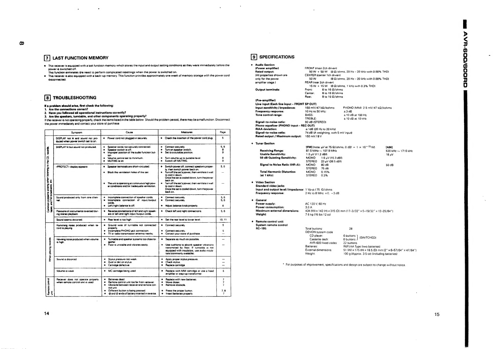
[7]
Last
FUNCTION
MEMORY
©
This
receiver
is
equipped
with
a
fast
function
memory
which
stores
the
input
and
output
setting
conditions
as
they
were
immediately
before
the
power
is
switched
off.
This
function
eliminates
the
need
to
perform
complicated
resettings
when
the
power
is
switched
on.
@
This
receive:
ts
also
equipped
with
a
back-up
memory.
This
function
provides
approximately
one
week
of
memory
storage
with
the
power
cord
disconnected.
TROUBLESHOOTING
tf
a
problem
should
arise,
first
check
the
following:
1.
Are
the
connections
correct?
2.
Have
you
followed
ail
operational
instructions
correctly?
3.
Are
the
speakers,
turntable,
and
other
components
operating
properly?
It
the
receiver
is
not
operating
property,
check
the
items
listed
in
the
table
below
Should
the
problem
persist,
there
may
be
a
malfunction.
Disconnect
a
ee
ee
eee
DISPLAY
not
kt
and
sound
not
pro-
@
Power
cord
not
plugged
in
securely.
®@
Check
the
insertion
of
the
power
cord
plug.
duced
when
power
switch
set
to
on.
the
power
unmediately
and
contact
your
store
of
purchase
DISPLAY
tt
but
sound
not
produced.
@
Speaker
cords
not
securely
connected.
°
©
Speaker
switch
is
off.
@
improper
position
of
the
audio
function
but-
ton
@
Volume
control
set
to
minimum.
@
MUTING
is
on
-PROTECT-
display
appears
@
Speaker
terminals
are
short-circuited.
©
Block
the
ventilation
holes
of
the
set
©
The
unit's
operating
at
continuous
high
pow-
@1
Conditions
and/or
inadequate
ventilation,
‘Sound
produced
only
trom
one
chan
®
Incomplete
connection
of
speaker
cords.
nel.
©
Incomplete
connection
of
input/output
cords.
©
Left/right
balance
is
off.
Connect
securely.
Turn
on
speaker
switch.
Set
to
a
suitable
position.
Turn
volume
up
to
suitabie
level,
‘Switch
off
MUTING.
Switch
power
off,
connect
speakers
proper-
ly,
then
switch
power
back
on.
Tum
off
the
set's
power,
then
ventilate
it
well
10
cool
it
down.
Once
the
set
is
cooled
down,
turn
the
power
back
on.
Turn
off
the
set's
power,
then
ventilate
it
well
to
coot
it
down.
Once
the
setis
cooled
down,
turn
the
power
back
on.
*
Connect
securely.
Connect
securely.
Adjust
balance
knob
property.
Common
probiems
ansing
when
bsteneng
to
the
CD.
records.
tapes,
and
FM
broadcasts,
etc
Positions
of
instruments
reversed
dur-
@
Reverse
connections
of
left
and
right
spesk-
ing
stereo
playback.
os
of
left
and
nght
input/output
cords.
Sound
seems
distorted.
©
Rear
level
is
too
high
Humiung
noe
produced
when
re
@
Ground
wwe
of
turntebla
not
connected
Cord
is
playing
properly.
@
=
lacomplete
PHONO
jack
connection.
@
TV
oF
radio
transmission
antenna
nearby.
Howling
noise
produced
when
volume:
@
Turntable
and
speaker
systems
[00
clase
to-
ws
high,
gether
@
Floor
rs
unstable
and
vibrates
easily.
Sound
is
distorted
‘When
playing
records
©
Stylus
pressure
100
weak.
@
Dust
os
dist
on
stylus.
@
=
Canndge
detective
Check
left
and
right
connections.
Set
the
rear
level
to
lower
level
Connect
securaly.
Connect
securely.
Contact
your
store
of
purchase.
‘Separate
as
much
as
possible.
Use
cushions
to
absorb
speaker
vibrations
transmitted
by
floor.
If
tumtable
1s
not
equipped
with
insulators,
use
audio
insula:
tors
{commonly
avaiable}.
Apply
proper
stylus
prassura.
Check
stylus.
Replace
cartridge
Volume
1s
weak
@
MC
cartridge
being
used
Receiver
does
nol
operate
proparly
©
Battones
dead
when
remote
control
unt
1s
used
@
Remote
control
unit
too
far
from
recewer.
©
Obstacle
batween
receiver
and
remote
con-
trol
unit
®
Oifferent
button
is
being
pressed.
@
=
@and
O
ends
of
battery
inserted
in
reverse.
Remote
contol
unit
Replace
with
MM
cartridge
or
use
a
head
amplifier
or
step-up
transformer.
Replace
with
new
batteries.
Move
closer.
Remove
obstacle.
Press
the
proper
button.
Insert
bettenes
property.
14
[9]
SPECIFICATIONS
@
Audio
Section
(Power
amplifier}
Rated
output:
{All
properties
shown
are
only
for
the
power
amplifier
stage.)
Output
terminals:
(Pre~amplifler)
FRONT
{main
2ch
driven)
50W
+
50W
(8
2/ohms,
20
Hz
-
20
kHz
with
0.08%
THD}
CENTER
(center
Ich
driven}
50
W
(8
Q/onms,
20 Hz
-
20
kHz
with
0.08%
THD}
REAR
(rear
2ch
driven)
1SW
+
ISW
(8
Qsohms,
1
kHz
with
0.3%
THD}
Front:
6
to
16
Q/ohms
Center:
B
to
16
Q/ohms
Rear:
8
to
16
Q/ohms
Line
input
{Each
line
input
-
FRONT
SP
OUT)
Input
sensitivity
/
impedance:
Frequency
response:
Tone
control
range:
Signal-to-noise
ratio:
150
mV/47
kQ/kohms
PHONO
(MM):
2 5
mV/47
kQ/kohms
10
Hz
to
50
kHz:
#308
BASS:
+10
dB
at
100
Hz
TREBLE:
£10
dB
at
10
kHz
92
dB
(STEREO)
Phono
equalizer
{PHONO
input
-
REC
OUT}
RIAA
deviation:
Signal-to—noise
ratio:
Rated
output
/
Maximum
output:
©
Tuner
Section
Receiving
Range:
Usable
Sensitlvity:
50
dB
Quieting
Sensitivity:
Signal
to
Noise
Ratio
(1HF-A):
Tots!
Harmonic
Distortion
(at
1
kHz):
©
Video
Section
Standard
video
jacks
Input
and
output
level
/impedance:
Frequency
response:
©
General
Power
supply:
Power
consumption:
Maximum
external
dimensions:
Weight:
@
Remote
control
unit
System
remote
contro}
RAC-195:
+
10B
(20
Hz
to
20
kHz)
74
dB
(A
weighting,
with
5
mV
input)
150
mV
/8V
FM]
(note:
uV
at
75
Q/ohms,
0
dBf
=
1 x
107'S
Wh
[AM]
87.5
MHz
~
107.9
MHz
520
kHz
~
1710
kHz
1.0
4V
01.2
dBA
18
pV
MONO
1.6
pV
(15.3
gBf)
STEREO
23
pV
(38.5
dBf)
MONO
8048
50
dB
STEREO
75d8
MONO
0.15%
STEREO
0.3%
1Vp-p/75
Q/ohms
2
Hz
to
8
MHz
+0,
-3dB
AC
120
V,
60 Hz
3.0A
434
(W)
x
142
1H)
x
315
{D}
mm
(17-3/32"
x
§-19/32"
x
12-25/64")
7.6
kg
(16
tbs
12
02}
Tota!
buttons:
28
DENON
system
code
CD
player:
6
buttons
Cassette
deck
6
buttons
}
ISWITCHED)
AVR-600
fixed
codes
22
buttons
Batteries:
R6P/AA
Type
(two
batteries)
External
dimensions:
51
(W)
x
175
(H)
x
18.5
(DI
mm
(2”
x
6-57/64"
x
47/64")
Weight
100
g
(Approx.
3
5
02)
{including
batieries)
*
For
purposes
of
improvement,
specifications
and
design
are
subject
to
change
without
notice
15
OOO
S/OOS
uy
mal

ae
eee
eee
OS
SOO/SOORD
mt
BR
AVF
O/C
OCR
amma
naar
ee
na
IO
IE
PTS
ED
WIRE
ARRANGEMENT
DISASSEMBLY
(To
reassemble
reverse
disassembly)
In
case
of
wires
require
unclasping
or
loosening
to
move
the
location
to
perform
adjustment
or
part
replacement,
be
sure
to
1.
Top
Cover
3.
Front
Mold
Panel
rearrange
them
neatly
to
restore
properly
in
the
same
iocation
as
they
were
originally
placed,
or
causing
to
produce
a
noise
R
4
@
43
@®
1)
Pull
out
Vol
knob
@
nd
3
round
knob:
®
may
occasionally
occur.
jemove
4
screws
(1)
and
3
screws
(2).
)
Pull
out
Volume
kno
a
rou
Ss
(5).
2)
Remove
4
nuts
(6).
3)
Remove
2
screws
@).
Top
Cover
Front
Mold
Panel
2.
Front
Aluminium
Panel
4.
Rear
Panel
Remove
4
screws
(3).
1)
Disconnect
cord
bush
(0).
2)
Remove
8
screws
(7),
and
15
screws
(2).
*
Screws
(2)
is
tighten.
@®
Front
Aluminium
Panel
Rear
Panel
AVR-600/GOORD
a
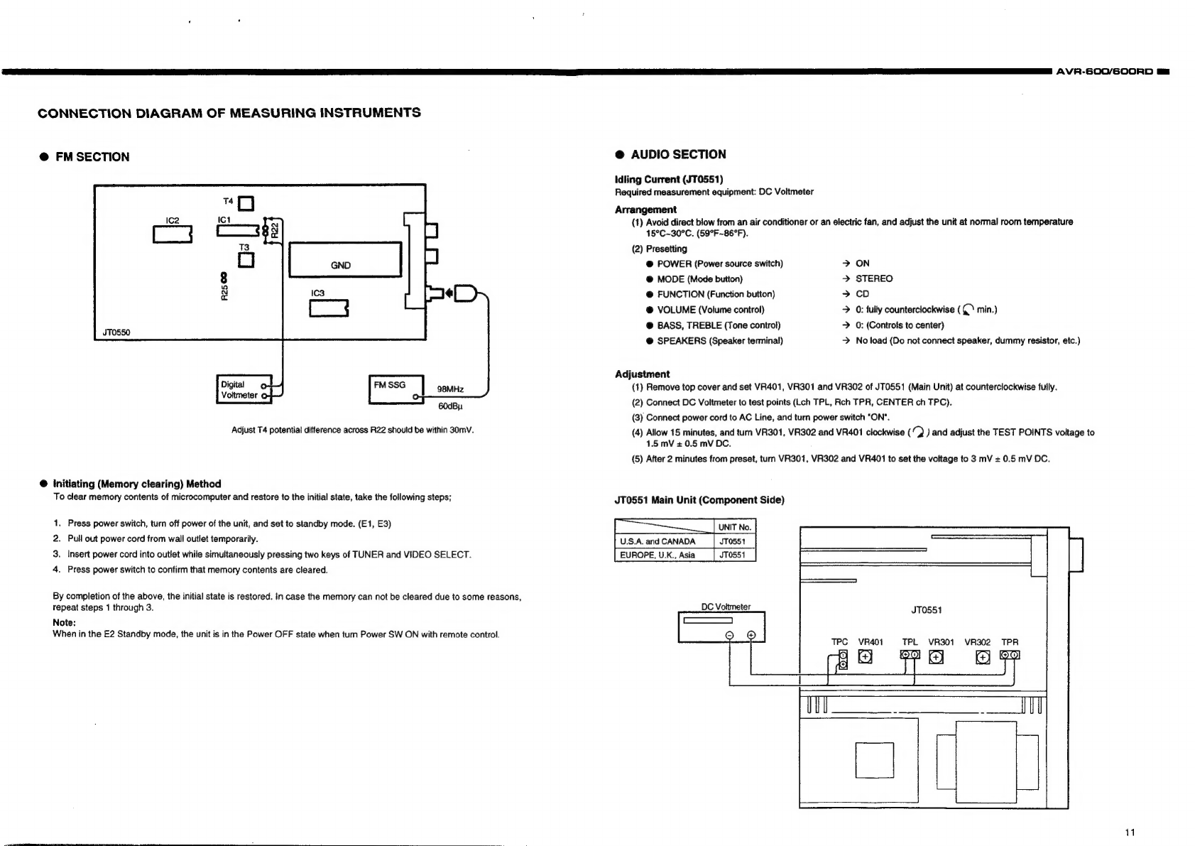
CONNECTION
DIAGRAM
OF
MEASURING
INSTRUMENTS
@
FM
SECTION
:
@
AUDIO
SECTION
Idling
Current
(JT0551)
Required
measurement
equipment:
DC
Voltmeter
Arrangement
(1)
Avoid
direct
blow
from
an
air
conditioner
or
an
electric
fan,
and
adjust
the
unit
at
normal
room
temperature
15°C~30°C.
(59°F
~86°F).
(2)
Presetting
@
POWER
(Power
source
switch)
>
ON
@
MODE
(Mode
button)
>
STEREO
¢
@
FUNCTION
(Function
button)
>
cD
@
VOLUME
(Volume
control)
>
0:
fully
counterclockwise
(CY
min.)
@
BASS,
TREBLE
(Tone
control)
>
0:
(Controls
to
center)
@
SPEAKERS
(Speaker
terminal)
>
No
load
(Do
not
connect
speaker,
dummy
resistor,
etc.)
—
Adjustment
Digital
~]
98MHz
(1)
Remove
top
cover
and
set
VR401,
VR301
and
VR302
of
JT0551
(Main
Unit)
at
counterclockwise
fully.
Voltmeter
o
=
(2)
Connect
DC
Voltmeter
to
test
points
(Lch
TPL,
Rch
TPR,
CENTER
ch
TPC).
(3)
Connect
power
cord
to
AC
Line,
and
turn
power
switch
"ON".
Adjust
T4
potential
difference
across
R22
should
be
within
30mV.
(4)
Allow
15
minutes,
and
tum
VR301,
VR302
and
VR401
clockwise
(/
)
and
adjust
the
TEST
POINTS
voltage
to
1.5
mV
+
0.5
mV
DC.
(5)
After
2
minutes
from
preset,
tum
VR301,
VR302
and
VR401
to
set
the
voltage
to
3
mV
+
0.5
mV
OC.
60dBy
@
initiating
(Memory
clearing)
Method
To
clear
memory
contents
of
microcomputer
and
restore
to
the
initial
state,
take
the
following
steps;
JT0551
Main
Unit
(Component
Side)
[|__|
Uni
No
|
U.S.A.
and
CANADA
JTO551
EUROPE,
U.K.,
Asia
JTO551
.
Press
power
switch,
turn
off
power
of
the
unit,
and
set
to
standby
mode.
(E1,
E3)
.
Pull
out
power
cord
from
wall
outlet
temporarily.
Insert
power
cord
into
outlet
while
simultaneously
pressing
two
keys
of
TUNER
and
VIDEO
SELECT.
A
wp
o
Press
power
switch
to
confirm
that
memory
contents
are
cleared.
By
completion
of
the
above,
the
initial
state
is
restored.
in
case
the
memory
can
not
be
cleared
due
to
some
reasons,
repeat
steps
1
through
3.
Note:
When
in
the
E2
Standby
mode,
the
unit
is
in
the
Power
OFF
state
when
turn
Power
SW
ON
with
remote
control.
DC
Voltmeter
JT0551
TPL
VR301
VR401
S
S
VR302
TPR
1
ia
a
Fee

=”
AVR-5O0/S00RD
12
SEMICONDUCTORS
@IC’s
TMP87CM71F-6314
(IC701)
Detect
power
stop
(“L”
at
power
stop)
Protection
input
(“H”
at
protection)
WACK
|
0
pa
[vaste
[ot
¢
|
—
|
—
J
2
[1
109176
(eiecton
VA)
contol
stobe
ouput
[9
[rest
||
=
fen]
—
[—]—[oomnecttogoud
Po
[Tuned
|
+
[—J
eu
|
tw
|
2
|
—
|W
atstereo
recove
pay
OTT
Te
Te
Fines
curpiton
[32
[RESET
teu
[i
[2]
—
[Reset
pis
[xn
|
—
|
—
[cei
creat
any
SSS
Pia
[x
our
LO
[=
—
[|
|
[ecciating
creat
tay
pis
[eno
[=
fond]
—
[Joona
[ie
[Ros
stant
|
—|
eu
[ea[
2
|
—
[0s
cals
Stat
signalinpat
(Croup
id
iz
[REWOCON
[I]
—
|
Eu
[eat
|
Z|
—
|
Remote
contre
signal
input
[ie
[stenco
J
[
—Peu
|
—
[2
|
[rat
TUNER
stereo
eceve
[ia
[Ros
ck
1
—
feu
8
[2
|
—
[Rs
docking
crag
[20
[aps
cara
[1
[—|
eu
|
S|
2
|
—
[ROS
datainput
(crore
Par
aps-reser
[Oo
|
N
|
eu]
—|
2
|
©
[ROSresetsigna
ouput
UO7OMy
[ea
fru
cK
OTN
feu
|
—
|
2
|
0
[uMT00%
contol
dock
oupet
Pas
fri
sre
OTN
|
eu
—]
2
|
&
|
imroor
cornet
stobe
out
[aa
[Pu
DATA
[-O
|
N|
€u
|
—|
2
|
C
|
UMT001
conmol
data
utp
——d
[25
[FuNG.OaTA
|
~O-|
-¢
[—
|
—|
2
|
1
|Lc7a20
Function
iC)
contr
data
ouput
[26
|FuNG.ck
oO
[-¢
|
—
|
—
[2]
crass
Function
iC)
contol
cock
output
FUNG.sTs
|
0
|
-¢
[=|
—J
2
|
[creas
(Function
i)
conto
stobe
output
[28
[stimono
|-o[-c[
—
|
—
[2
|
1
TUNER
STEREOIMONO
contol
ouput
(Lat
STEREO)
|
[es
|powenorF
|
o[cl[—|—[2z};t[vaw
[30
[vou
bown
To
|e
TT
—
J
2
[1
[electicaty
driven
volume
contol
output
GARDE)
|
*
port
is
fixed
“L”
at
RDS
non-selection
mode.
DENO-00301
/
Druck2
el
Pee
e
ee]
=
sr
Pat
fvonue
|
oO
|
©
|—]—|
#
|
1
|
electrically
criven
volume
contral
output
(BABS085)
ae
[sprRonT
|
0
|
6
[ea]
—
|Z
|
A
|
Frontspeaker
relay
contol
ouput
En
eS
ae
|
34
[tep.pRO-
|
Of P|
id
|
—
ft
{[
t
[DOLBY
PROLOIC
indecating
LED
drive
output
(H"
at
light)
Pas
[teo.stey
|
O
|
|i
|
—|t
|
1
|
Standby
indecatng
LED
dive
output
(Hr
atigh)
Yd
pate
|
OL
PF]
]S]tlt
[ADconmtomt
SSS
Par
fee
POL
a
TST
Le
[PD
cones
output
Passe
PP
Pa
SP
tL
[FLO
cones
oupat
pataa
i
OP
PP]
S|
ct
|
c
[PD
contr
output
paofss
sf
Of
PP
a]
—]
2
|
1
[rtd
conto
output
partes
POT
ep
eT
Pe
Pe
[aD
conwe
opt
palma
fof
efi
{—|
1
|
©
[FLD
contol
output
rates
+f
OL
PL
@]—|
tL
[RD
contol
opt
Pas
tea
POP
Le
Pf
©
[RD
contol
output
pas
fog
oe
Pa
[Te
Pe
[rb
eontotoupat
pepe
Pot
ea
TP
e
Pe
[rb
convotoupat
par
fas
oy
ea
[Pepe
[rb
conreoupt
SSS
Pasta
olr|wi{—li]c]
Patuepofetm/—itf.|
EL
rsi[em
foftelwl—li{e
ps2
fro
fof
ei
Pet
psafe@
Po
fe
Tig
PP ee
|
EI
ee
pssfp@
POT
e
Po
PHT
EI
ee
ee
rer
{rm
foltr|a{—|[t|.
pss
fPg
oe
fie
|
e
Pe
[Ab
contoloutpat
—SS
pss
fPw
ote
Pa
[=P
Te
[Deon
Peo
trim
POP
eR
Pia
[|e
Pe
[rb
contotoupt
Per
fr
oe
Pia
{=P
CT
[ro
contolout
pe
lPo
oe
Te
[HT
[aD
conrotopat
SSS
Pestp@
Pope
[a
[—[t
lc
[ron
oupt
petro
ote
Ta
[Tey
[aD
conmet
out
pes
[Py
oye
a
[HP
[et
[AD
contotoupet
SSS
[es
[va
tf
|
|
—
[ocomeoctio
vie
[er
[oo-oK
To
|W
|
eu
|
TZ
[A
[NIU97016
(Delay
time)
control
dock
output
[6
[OD-REQ
TO
|
N
|
eu
|
—
|Z
|
-H
|NIU97016
(Delay
time)
control
request
outpet
[69
|op.data
FO
|
N
|
eu
|
—
[Z|
_H
[NIUG701G
(Delay
time)
contol
data
output
[70
[woes
TN
tg [=
[Z|
—
[Select
occurring
of
no
ROS
function
CH”
at
occuring
ADS
function
[71
[veo
oN
|
eu
|
=
[Z|
[804066
(Video
shi)
contol
output
(L"at
selecting)
[72
[videos
[0
|
N
|
eu
|
—
JZ
|
-H
|
804066
(Video
shit)
controt
ouput
(L"at
selecting)
[73
[evs
ev
iv
|Z
|
Jeutoningts
[74
[revs
eu
fv
[2
|
eutoninpts
[7s
[eeva
feu
fv
[2
|
|
Buttoninpats
[76
[Reve
eu
[tv
|
|
J
eaton
inp?
Paz
[Reve
fev
tv
|
z
[—
[Bumonipatt
[
78
[Mone
|
[eu
|
tv
[2
|
—
[Model
version
changamput
[ve
[rumere
ON
[eu
|
[2
[0
[tuner
muting
output
CU"
at
muting)
Cd
a
os
[2
[Fixed
output
on
“H
*
port
is
fixed
“L”
at
RDS
non-selection
mode.

AVR-600/600RD
mm
LA1265
(S)
(1001)
BA6208S

mm
AVR-GOC/GOORD
14
M7001
(IC003)
8
xno
16
XOUTO
i
FMINO
Bees
AMIN
©
a
er
Ae
Terminal
Description
SsYC
:
Clock
for
controller
(400
kHZ).
XIN,
XOUT
:
X'tal
OSC
(7.2
MHz).
FMIN,
AMIN
:
Station
oscillation
signal
input.
CE,
CL,
DATA
:
Data
input.
Br
BO,
BO2,
BO3,
:
Band
data
output.
BOT
is
feasible
for
time
base
output
(8
Hz).
Vop1,
Vob2,
Vss_:
Power
supply.
(VDD2
is
for
back-up).
Pot,
Po2
:
Charge
pump
output.
Data
Input
rit
t1
12
tt>
15
ps
ou
“TrLALn
igh
gy
eo
‘i.
t
t2<1.5
ps
(X'tal
at
7.2MHz)
’
rae
t
+
t
eee
9
2
1
pata
_[ooxorXo2X
""AIKReXS]
sw
‘
4
mma
ae
INTERINAL
DATA
x
———~—
Input
from
Do.
Foe
[o:
[oe
[os
|
[os
[oe
[or
[os
[oe
[ovw]onJowefore|
wo]
[eo
[er
[a]
[
ro
[mre]
s
|
(1)
DO
(LSB)~D13
(MSB):
Frequency
dividend
data
For
FMIN,
use
DO~013;
for
AMIN,
use
04~D13.
oo
[0+
|
ve
|
os
[04
|
os
|
ve
[or
|
02
|
ve
[ovo]
or
fore]
oro
0
1
°
0
0
0
oO
1
iY)
1
4
1
0
1.
+
FMIN
Frequency
dividend
nnumber
=
14853
LSB
MS8
x
x
x
x
y 0 0
i)
ty)
1
tt)
1 1
1.
—
FMIN
Frequency
dividend
nnumber
=
928
LSB
MBS
(2)
TO,
T1:
For
test
of
LS!
(0,
0)
LC78212
(IC102)
30
LC78212
Terminal
Function
Name
of
Terminal
|
'/O
|
Equivalent
internal
Circuit
Function
of
Terminal
Voo,
Vss,
Vee
Power
terminal.
L1~L8,A1~
RS
LCOM1
~
LCOM4,
Refer
to
block
diagram
In/Out
terminat
of
analog
switch.
8COM1
-
BCOM4
Serial
data
input
terminal
(Schmidt
buffer).
Oo—_f>—_
CL
=
Clock
input
terminal.
CL,
01,
CE
'
Di=
Data
Input
terminal.
CE
=
Chip
enable
terminal.
Selection
terminal
for
using
of
two.
Address
will
be
shitted
as
per
below
table
when
switching
S
terminal
to
L
or
H.
:
Address
Name
of
item
|
Sterna)
[—————Adstess
|
s
1;
o-p—
Coal
pao [ar
[a2
|
as
|
|
o—_t>—
Reset
terminal.
Condition
of
analog
switch
is
not
fixed
at
the
time
of
tuming
on
the
power.
When
shift
this
termnai
to
L,
all
analog
switches
become
OFF.
NJU9702
(
1C202)
LPFYIN
VooL_j1
24L_
J
Vee
XIn[_]2
23
{—]
LPF
1
IN
ee
xouTE_
Js
22
f
J
LPF1
OUT
REQT_}4
scx(_]5
paTaL_46
tosw(_]’”
BT
Fcct
iorLac[_}®
7F}cc2
test
1{_]?
16
FF")
op2
in
Test
2[_]
'
18
FF)
ope
our
peno(_}""
14
FF)
LPr2
IN
'3F5
pre
our
XIN
LPF1OUT
OP1
OUT
OP1IN
CCt
OSCILLATOR
XOUT
REQ
SCK
DATA iDSW
IDFLAG
TEST:
TEST2
DGND AGND
Voo
Vcc
DELAY
TIME
CONTROL
A
Ems.
CC2
OP2ZIN
OP2
OUT
LPF2IN
LPF2
OUT
sone
a
21
f—J
opt
our
i
+
{Moo}
[DEM]
HN
|
sBew
|
fo
eth
et
me
aaa
AVR-600/GOCORD
am
15

AVR-600/6O0ORD
Bt
@8
AVA-GO0/GOORD
BA4558F
(1C101,
103)
TC9176P
(
1G262)
SAAG579T
SAA6579T
Terminal
Function
$I-18752
(C911)
Panel
combo
=
ETS
(IC501,
502)
|
1_|Quar
|
Quallty
indication
output,
[2
[RDA
|RDSdataoupu.
fncit
7
Fr
:
2
[3
[ret
|
Reference
voltage
output
(0.5
vooa).
_|
ain
;
i
|
4
[mux
5:
Vee
:
Voo
GND
Vss
1
|
5
[Vpoa
__|
+5V
supply
voltage
for
analog
part.
4:
OUTPI
:
O
T6
[Vesa
|
Ground
for
analog
part
(ov).
|
Si4¥e0
ourpur.
Vee
vERTING
ovate
Ts
[scout
_|
spcanier
output
of
reconstruction
filter.
NON
VERTIS
AVERTING
[2
[MODE
|
Oscillation
modenest
controt
input.
|
pate
NON
BVERTNG
[10
[Test
_|Testenable
input.
were
i
11
|Vsso
|
Ground
for
digital
part
(OV).
|
i
|
12
|vooo
_|
|
45V
sup
supply
voltage
for
dic
voltage
for
digital
part.
_|
part.
tom
at
Pegs
ena
1a
fosei
;
Pe)
CL
Ly
Cpe
am
[14
[Osco
|
Oscitlatoroup.
BA4558
(IC261,
263)
eat]
{]
tr)
Cl
ee
|
45_|
157
BA15218
(IC451)
mt
lst
1]
st
|
«|
tee
16
|
RDCL
ASH
5 &
ASW
ped
ECC
2]
8
ted
oy
te
trata}
aa
|
ee
aE:
:
ot]
COC)
[pa
ae
elt]
C1
CT]
freed
:
a
an
|
BUSO66BCF
BU4066BC
oer
‘e
%
iG
ee
|
(1C203,
205)
(1C601)
“or
eae
Peet]
1]
CO)
:
ae
ti
WT
aH
|
sl
el
lal)
=|
t=
one
PoP
sL
tet
ei
{574
SeiHHH
As
|
:
tae®
{AS
ASW)
2
rine
mil ion
1
ee
Gis
ee
Se
NJM2177AF
(1C201)
BELBSES
nn
ale.
SBSSEARESBSRESRS
Bu4094BC
LC7074M
20
(IC913,
914)
(IC912)
3
:
—
7
ase
osc!
osc2
8
BATA
Vsst
Vss3
ao
Vss2
—>
CLOCK
OUT
ar
RES—>
—>
DATA
OUT
2
CLOCK
IN—>
—>
DATASTART
COCK
o
8
of
DATAIN—>
—>
ERROR
l
as
>
—>
CORRECTION
gzu<opee
See
ssss
SOUT
LPFAN
LR
LA
16
CORR.SEL
srbsypccecess
,
vss
CLEDSEL—>
—DS.CONTROL
BsBSSS
a
Voo
—>
RECEIVE
39
ee
16
17

GE
AVR-600/GO0ORD
NJM7912FA
KIA7806P1
(1C503,504)
(10551)
Output
Input
GND
@
OTHERS
$BX1610-52
(Remote
Control
Sensor)
Wr
y
1c1
Ut
01
125°
5
C1,C2,C4:
c=
|
o3
1.
Vee
STANDARD
mn
2.
Output
R2
=
a
TRANSMITTER
Ra,
4
4,
Case
Fin
5.
Case
Fin
18
e@
IC
PROTECTORS
ICP-N20
(PR505
,506)
:
CX20106A
Chip
:
PIN
Photo
Diode
Chip
Aluminum
Electrolytic
Capacitor
:
SL
Characteristic
5%
:
Gain
Adjuster
:
fo
Adjuster
+1%
USE
145%
@
TRANSISTORS
2SA970
(BL)
2SB647A
(C)
2SA988
(E/F)
2SD667A
(C)
2S8C1015
(GR)
2SC1815
(Y),(GR)
2SC1841
(E/F)
2$C2058
(Q)
2$C2878
(A/B)
B
(Base)
C
(Collector)
E
(Emitter)
B
(Base)
C
(Collector)
E
(Emitter)
DTA114ES
2SA933S
(S)
DTA114TS
2SC1740
(S)
DTA143ES
DTC114ES
DTC144ES
DTC144TS
DTC323TS
B
(Base)
B
(Base)
C
(Collector)
C
(Collector)
E
(Emitter)
E
(Emitter)
DTA114EUA
DTC143EUA
DTC143EUA
DTC144EUA
DTC144EUA
3
Rt
OuT
te,
R2
GND
GND
2
1
ria
DTA114EUA
3:
Out
Rt
out
“ W
out
Re
@ND
GND
AVR-6GOO/600RD
mm
28C2458
B
(Base)
C
(Collector)
E
(Emitter)
2SK161
G
(Gate)
S
(Source)
D
(Drain)
19

[3
AVR-600/GOORD
@DIODES
(included
LED)
1N4148
HZ9A3
HZ7B1
SLR-54
S4VB20
182471
HZS6C
HZ3C2
H227
,
ia
a
am
E
+e
we
Black
Black
.
oo
SRS
Ys
+
Short
Long
(Cathode)
{Anode)
FLD
(FL701)
RDS EON
TA
TP
RT
PRY
TUNED
AUTO
RFATT
MEMO
CH
TAPE
12
'
146
ae
oe
bode
h
km
Wy)
7,
ADS
EON
TA
TP RT
PRY
TUNED
STEREO
AUTO
RFATT
MEMO
CH
TAPE
12
“IM
p
-
a
6)
19G126
116 106
9G
8G
76 6G 5G
4G
3G 2G
1G
te
4
2
PIN
CONNECTION
femne.
[i
fetstafs{o]z[o]
s
[rom]
wl
|u|
15
|
sie
ee
eel
tesla
|
Pano.
a7]
[ef
aolafolalule]
N°
yp
Nop
cones
fo]
ses
[rs]
s0[o[ss[es]re[]w[re|ra]
3}
N°
Roseman
5)
1G~14G-——~
Gird
Filament
ANODE
CONNECTION
20
1
AVR-600/S6OORD
El
NOTE
FOR
PARTS
LIST
@
Part
indicated
with
the
mark
°@"
are
not
always
in
stock
and
possibly
to
take
a
long
period
of
time
for
supplying,
or
in
some
case
supplying
of
part
may
be
refused.
@
When
ordering
of
part,
clearly
indicate
“1°
and
"!”
(i)
to
avoid
mis-supptying.
©
Ordering
part
without
stating
its
part
number
can
not
be
supplied.
@
Part
indicated
with
the
mark
"x"
is
not
illustrated
in
the
exploded
view.
@
Not
including
Carbon
Film
+5%,
1/4W
Type
in
the
P.W.
Board
parts
list.
(Refer
to
the
Schematic
Diagram
for
those
parts.)
WARNING:
Parts
marked
with
this
symbol
A\
iilMnave
critical
characteristics.
Use
ONLY
replacement
parts
recommended
by
the
manufacturer.
@
Resistors
@
Capacitors
Ex:
BN
14K
2E
182
G
ER
Ex:
CE
O4W
1H
282
M
BP
Type
Shape
Power
Resist-
Allowable
Others
Type
Shape
Dielectric
Capacity
Allowable
Others
and
per-
ance
=
error
and
per-
strength
error
formance
|
|
|
|
tormance
>
Aluminum
toi
electrolytic
:
Aluminum
sold
slectrolytic
:
Tantalum
electrolytic
Fin
;
Pulse-resistant
type
:
Low
noise
type
:
Non-buming
type
Fuse-reaisior
:
Lead
wke
forming
:
High
etabliity
type
Non-polar
type
o
7
:
Ripple-roaistant
type
i
For
change
and
diecharge
©
Units:
ohm
z
=
=1.20hm
1-digit
effective
number.
2-digit
effective
number,
decimal
point
indicated
by
R.
dee
kK:
:
Ceramic
M:
:
For
asauning
high
frequency
:
Ceramic
z:
:UL
part
Oil
:GSA
part
2
=>
1800
ohm
=
1.8
kohm
:Mica
P:
:UL-CSA
type
Indicates
number
of
zeros
atter
attective
number.
:
Metatized
t
Lead
ware
forming
2-digit
effective
number,
:
Metathzed
4
e:
%
Capacity
(electrolyte
aay
Units:
¢
Units:
ohm
t
tien
tena
number
of
zeros
after
effective
number.
2-digit
effective
number.
©
Units:
pF.
2.8
2
=
2.2uF
t
t____
1
-digit
attective
number.
2-digit
effective
number,
decimal
point
indicated
by
R.
*
Units:
pF.
%
Capacity
{except
electrolyte)
=
—
2200pF=0.0022yF
(More
than
2)—
Indicates
number
of
zeros
after
effective
number.
2-digit
effective
number.
Units:
pF.
L
=
—-220pF
(0
or
1)
Indicates
number
of
zeros
after
effective
number.
2-digit
effective
number.
©
Units:
pF.
When
the
dielectric
strength
is
indicated
in
AC,
"AC"
is
included
atter
the
deetectric
strength
vaiue.
21

i
i
ee
lela
=lelel-;em
|
PARTS
LIST
OF
P.W.BOARD
TUNER
P.W.B.
SUB.
ASS'Y
MAIN
P.W.B.
ASS'Y
|
Ref.No.
|
PartNo.
|
Part
Name
Remarks
No.
2
|
Remarks
a'ty|
Part
No.
Part
Name
Remarks
Part
Name
Remarks
Europe/
SEMICONDUCTORS
GROUP
9L2
1363
13.
|Low
pass
filter
FB-75G
SEMICONDUCTORS
GROUP
0307-310
|
9L2
3312
32M)
Diode
1824718
263
0891
001
|IC
LA1265S
10451
263
0565
007]
IC
BA15218
0311,312
|
276
0375
002}
Diode
NAGS}
Of
INS
263
0439
007
|
1C
LA3401
9L2
1363
14
iLow
pass
filter
19kHz
4
CAV
4
262
0719
009
|
IC
LM7001
sss
4
Pe
i
Smee
ane
ICS51
9LC
K044
71
|
IC
KIA7806Pi
D352
276
0375
002}
Diode
1N4531
or
1N4148
9L2
1363
13
|Low
pass
filter
FB-75G
Ic9t1
262
1701
906|
iC
SAAG579T
Europe/U.K.
model
D401
276
0375
002)
Diode
1N4531
or
1N4148
ic912
9LC
K044
71
|
1C
LC7074M
Europe/U.K.
model
D403
276
0375
002}
Diode
1N4531
or
1N4148
1€913,914
|
262
1968
008]
IC
BU4094B
D405
276
0375
002]
Diode
1N4531
or
1N4148
0407
9L2
3312
32M]
Diode
182471B
TR301~304]
271
0094
016]
Transistor
2SA970-BL
0409
912
3312
32Mi
Diode
1824718
TA305,306
|
271
0131
021]
Transistor
26A988-E/F
att
276
0375
002|
Diode
1N4531
or
1N4148
TR307~312}
273
0235
020]
Transistor
25C1841-E/F
D441
276
0375
002|
Diode
1N4531
or
1N4148
TR313,314
|
273
0325
008}
Transistor
26C1815-GR
481,482
|
2760375
002}
Diode
1N4531
or
1N4148
TR315,316
|
274
0060
007]
Transistor
2SD667A-C
TR317,318
|
272
0053
005
|
Transistor
2SB647A-C
D801
916
0053
008}
Diode
1N4002
TR319,320
|
273
0430
003!
Transistor
25C4278-E/F
802-804
|
276
0375
002]
Diode
1N4531
or
1N4148
TR321,322
|
271
0276
009/
Transistor
2SA1633-E/F
TR323,324
|
273
0235
020)
Transistor
26C1841-E/F
D905
276
0375
002}
Diode
1N4531
or
1N4148
i
TR325
271
0131
021|
Transistor
25A988-E/F
0911,912
|
276
0375
002}
Diode
1N4531
or
1N4148
:
TR351,352
|
271
0131
021]
Transistor
254988-E/F
TR353
|
273.0303
910!
Transistor
26C1740S-S
20351
91.2
3321
61M|
Zener
diode
HZ27-04
TR354
271
0192
002|
Transistor
2SA933-S
TR355
—_|
9L2
3286
25T|
Transistor
2SB647C
20551
276
0051
041]
Zener
diode
HZ7B1
912
3631
97
}1C
4066BC
TROO!
275
0051
006
|
Transistor
2SK161
Europe/U.K.
model
912
6225
21
[Switch
SL2-2
TROO2
Transistor
2SC2058S-Q
TRO03,004
Transistor
DTA114ES
9LB
J002
51
|AM
IF
trans
TROOS
Transistor
2SC1815Y
912
1370
33.
{FM
Det.
trans
TROOS
Transistor
25C1815Y
TROO7,008
Transistor
DTC323TS
9L2
4286
51
|Tuner
pack”
TROO9
Transistor
DTC144TS
TRO10
Transistor
DTA114TS
SLH
HO00
31
|Tuner
pack
TR601,602
Transistor
2$C2458-BL
TR603,604
Transistor
2SA1015GR
9L2
1701
32
|
Crystal
72MHz
001-003
Diode
1N4118
or
1N4531
9LJ
705501
{Tuner
P.W.B.
Sub,
Assy
006
Diode
1N4001
9LJ
1055 02
|Tuner
P.W.B.
Sub.
Ass'y
616,617
Diode
1N4118
or
1N4531
9LJ
7055
03
[Tuner
P.W.B.
Sub.
Assy
9LJ
T055
06
{Tuner
P.W.B.
Sub.
Ass'y
TR401
|
274.0094
016]
Transistor
2SA970-BL
Z0801
|
276
0299
007;
Zener
dioda
HZ3C2
TR403
|
271
0094
016]
Transistor
2SA970-BL
TR405
|
271.0131
021]
Transistor
2SA988-E/F
273
0235
020]
Transistor
25C
1841-E/F
RESISTORS
GROUP
Hed
ikccetied
Blaaraapee
cra
oa
R915-918
|
247
2969
052]
Carbon
film
2.2
kohm
1/4W
(NB)]
RID
4B2E222,NB
319,320.
/9LATO11
74A|
Fusible
resistor
68
ohm
14W_
|
RDIAB2EGAOJFR
piicere
eal
a
sraieetei
fa21-324
|
241
2369 023|
Carbon
fim 130 ohm
1/4W
(NB)
|
RD14B2E131
NB
i
sssiacl
ve
a
ieuake
R331,932
|
241
2821
045|
Carbon
fi220
ohm
1/4W
(NB)}
RID14B2E221JNB
ec
stata
cde
aeeeee
383-340
|9LATO10
12A|
Carbon
fim
0.22
ohm
1W
(NB}}
ID
4B2ERZ2JNB
971-374
|9LA
TOtO
2A}
Carbon
fim
0.22
ohm
VW
(NB}}
RD14BZERZ2NB
es
NAT
Oe
Transietey
2A
1038
EFF
R384
_—_|9LATO11
74R!
Fusible
resistor
68
ohm
1/4W
|
RD14B222E680JFR
273
0235
020|
Transistor
28C1841-E/F
273
0253
028]
Transistor
2$C2878-B
269
0022
904)
Transistor
DTA143ES
269
0018
002]
Transistor
DTC143ES
273
0303
910}
Transistor
2SC1740S-S
271
0192
002]
Transistor
2SA933-S
269
0040
009)
Transistor
OTC144ES
CE04D1H010JBP
CE04W1HRIOM
SRA
CQQ3M1HS63K
ECOM
CQ93M1H473K
CE04W1HR22M
SRA
254
4254
789
|
Electrolytic
1000
pF/16V
CE04W1C102M
607,608
|
254
4252
079
|
Electrolytic
1000
pF/10V
CE04W1A102M
R408,409
|
241
2369
052)
Carbon
film
2.2
kohm
1/4W
(NB)|
RD14B2E222JNB
R410
9LA
T011
74R}
Fusibie
resistor
68
ohm
1/4W
|
RD14B222E680JFR
R411,412
|
241
2369
023!
Carbon
film
130
ohm
1/4W
(NB)
|
RD14B2E131JNB
R416
241
2321
045}
Carbon
fim
220
ohm
1/4W
(NB)
|
RD14B2E221JNB
R417~-420
/9LA
TO10
12R)
Carbon
film
0.22
ohm
1/4W
(NB)|
RD1482ER22JNB
R431
241
2321
032|
Carbon
film
4.7
ohm
1/4W
(NB)|
RD1482E4R7JNB
R433,434
|
241
2321
032]
Carbon
film
4.7
ohm
1/4W(NB)
|
AD14B2E4R7JNB
R481,482
|
241
2322
060)
Carbon
film
1
ohm
1/4W
(NB)
|
RO14B2E010JNB
OTHER
PARTS
GROUP
9LE
W000
11
|
Antena
terminal
board
9LB
HOOS
31
|
MW
Ant
coil
9L2
1349
92
|
Ceramic
fiter
CFL-SFE10.7MA8A
|
Except
Europe
modet
9LB
NOO1
01
|
Ceramic
fiker
CFL-SFT10.7MS2A
|
Europe/
U.K.
model
SLB
.NOO1
11
|
Ceramic
filter
CFL-SFE10.7MS2GA
|
U.S.A/Canada/
Asia
model
273
0303
910}
Transistor
25C1740S-S
269
0018
002
|
Transistor
DTC143ES
273
323
910
Transistor
25C1740S-S
269
0022
904]
Transistor
OTA143ES
VR301,302
|
9LO
1603
23
|
Semi
fixed
resistor
§
kohm
VR401
9LO
1603
23
|
Semi
fixed
resistor
5
kohm
9LA
Y001
81
|
Variable
resister
100
kohm
9LA
Y001
82
|
Variable
resister
30
kohm
SLA
Y001
83;
Variable
resister
10
kohm
9LB
POOS
01
|
Ceramic
filter
BFU4S0C4N
SLB
P004
91
|
Ceramic
filter
CMU2-456A16
269
0022
904}
Transistor
DTA143ES
Diode
1N4531
or
1N4148
QLE
R002
32
|
4P
US
pin
jack

RE
AV
AR-SOL/GOOR
DD
Sea
RR
Part
Name
-
Electrotyic
3200
WF/esV
|
CEOAW132M
CK14B1H221K
253
1174
018
|
Ceramic
0.01
pF/16V
CK14Y1C103M
U.S.A/Canada/
255
1085
006
|
Mytar
film
0.12
pF/S0V
CQG3M1H124K
ECOM
Asia
model
253
1174
018
|
Ceramic
0.01
pF/16V
CK14Y1C103M
304-306
|
253
1193
976]
Ceramic
220pF/SOV
:
CK14B1H221K
255
1258
053
Mylar
film
6800pF/SOV
CQS3M1H682K
ECOM
911,912
|
253.3613
001
|
Ceramic
27pF/S0V
CC14SL1H270J
309,310
r
CK14B1H101K
Europe/U.K.
model
313-316
COSGM1H102K
ECOM
C915
HMA
1000
163}
Caramic
560pF/50V
CK14B1H561K
317,318
i .
CK45=2A180)
Europe/U.K.
model
321,322
COS3M1H103K
ECOM
C919
253
1174
018
|
Ceramic
0.01
yF/16V
CK14Y10103M
325,326
|
253
1028
009]
Ceramic
220pF/500V
CK45B2H221K
Europe/U.K.
model
255
4213
972]
Mylar
film
0.01
pF/SOV
CQ93M1H103K
ECOM
SLA
L004
71
|
Electrolytic
8200
pF/SOV
Ge
0«w1H22M
SMH
255
1084
007
|
Mylar
fim
0.1
pF/S0V
CORaMIHTO4K
ECOM
|
I”
OTHER
PARTS
GROUP
255
1258
053}
Mylar
film
6800pF/SOV
‘COS3M1H682K
ECOM
OLE
D07
92
125P
FFG
or
Europe/U.KJAsia
mode!
253
1174
018]
Ceramic
0.01
pF/M6V
CK14¥10103M
255
1084
007]
Mytar
film
0.1
F/50V
CQGQM1H104K
ECOM
9LE
R002
41
|
1P
US
pin
jack
9LE
Y005
01
|
Headphone
jack
253
1193
976)
Ceramic
220pF/S0V
CK14B1H221K
U.S.A/Canada/
Asia
model
253
1193
976
|
Ceramic
220pF/50V
CK14B1H221K
255
1073
005]
Mylar
film
0.012
pF/SOV
CQ9SM1H123K
ECOM
HMA
1000
212
Ceramic
33pF
/50V
CC14SLIH330J
255
1120
000)
Mylar
film
1000pF/SOV
COSGM
1H102K
ECOM
9122273
63
|
Trap
coil
1
pH
9122273
63
|
Trap
coll
1
pH
9L2
6413
21
|
SP
Relay
24V
9LE
U004
01
|
Speaker
terminal
(C)
9LE
U003
81
|
Front
SP
terminal
9L0
2478
76R}
BC
Ceramic
cap.
18pF/100V
|
CK45=2A180J
Europe/U.K.
model
9L0
2476
82R|
BC
Ceramic
cap.
18pF/100V
|
CK45=2A330J
U.S.A/Canada/
Asia
model
255
4213
972]
Mylar
film
0.01
yF/50V
COS3M1H103K
ECOM
255
4213
972|
Mylar
film
0.01
pF/SOV
CQ83M1H103K
ECQM
253
1028
009}
Ceramic
220pF/500V
CK45B2H221K
255
1120
084)
Mytar
film
4700pF/S0V
CQS93M1H472K
ECQM
253
1174
018]
Ceramic
0.01
pF/16V
CK14Y10103M
285
1084
007)
Mylar
film
0.1
pF/SOV
CQS3M1H104K
ECOM
253
1174
018!
Ceramic
0.01
uF/6V
CK14Y1C103M
C433,434
|
255
1084
007}
Mylar
film
0.1
yF/SOV
CQ93M1H104K
ECQM
435,436
|HMA
1000
152)
Ceramic
100pF/50V
CK14B1H101K
Europa/U.KJAsia
model
455,456
JHMA
1000
183
Ceramic
100pF/S0V
CK14B1H101K
C459,460
|
255
1120
042}
Mylar
film
2200pF/50V
CQ93M1H222K
ECQM
C461,462
|
255
1087
004]
Mylar
fikn
0.18
pF/SOV
COS3MIHI184K
ECQM
467,468
|
255
1073
005|
Mylar
film
0.012
yF/SOV
CQQ3M4H123K
ECQM
C469,470
|
255
4187
008;
Myjar
film
0.056
yF/SOV
CQ93P1H56
C471,472
|
254
4196
928
|
Electrolytic
0.33
yF/SOV
CEOAWIHR33M
SRA
CA74
253
1025
002]
Ceramic
0.022
yF/SOV
CK14F1H223Z
498,499
|
255
1084
007)
Mylar
film
0.1
yF/SOV
CQS3M1H104K
ECOM
9LF
E001
81
|
Speaker
switch
9L2
1701
33
|
Crystal
4.332MHz
U.K.
/Asia
model
942
792071
|
Crystal
4.0MHz
U.K.
/Asia
model
SLM
F001
71
]
Insulation
sheet
9LJ
T055
11
|
Main
AIM
P.W.B.
Ass'Y
U.S.A/Canada
mode!
9LJ
T055
12
|
Main
AIM
P.W.B.
Ass'Y
Europe
model
QLJ
T055
13
|
Main
AIM
P.W.B.
Ass'Y
U.K.
model
GLI
T055
16
|
Main
AIM
P.W.B.
Ass'Y
Asia
mode!
C552
253
1174
018|
Ceramic
0.01
pF/16V
CK14Y10103M
24

NR
alae
ne
ee
ee
nee
nat nan
te
|
AVR-600/600R0D
AUDIO
P.W.B.
SUB
ASS'Y
FL
P.W.B.
SUB
ASS'Y
SEMICONDUCTORS
GROUP
OTHER
PARTS
GROUP
263
0672
903)
IC
BA4558F
SLE
Y000
98
|
10P
socket
(W}
9L.C
PO30
$1
|
IC
LC78212
SLE
YOOt
02
|
13P
socket
(W)
263
0672
903}
IC
BA4558F
Part
No.
Part
Name
SEMICONDUCTORS
GROUP
OTHER
PARTS
GROUP
263
0322
004
|
IC
BA4558
9LB
T005
31
|
Sub
power
transformer
262
0625
009|
IC
TC9176P
263
0322
004
|
IC
BA4558
9LB
T00S
32
|
Sub
power
transformer
263
0972
001
|
IC
BA6208
9LB
TO0S
33
|
Sub
power
transformer
SLE
R002
23
|
6P
US
pin
jack
263
0906
006]
IC
NJM2177AF
QLE
R002
22
|
8P
US
pin
jack
SLC
K050
32
|
IC
NJU9702G
262
1875
007)
IC
BU4066BCF
L201
9L2
1222
SAF
|
Inductor
120
pH
262
1875
007
|
IC
BU4066BCF
263
0855
005
IC
$118752
263
0516
001
|
IC
NJM7812FA
262
2190
011
|
IC
TMP87CM71F-6314
9LH
NOOO
31
|
IC
SBX1910-52
Remote
cotrol
senser
LF101,102
|
9B
J002
11
|
Low
pass
filter
SLC
A004
01R}
Transistor
OTA114EUA
TR202,203
|9LC
A003
91R|
Transistor
OTC144EUA
TR205
SLC
A0G3
91Ri
Transistor
DTC144EUA
399
0223
907
|
crystal
(CSA2.00MG)
TR206
SLC
A003
92R|
Transistor
DTC143EUA
TR207,208
Transistor
DTC144EUA
9LJ
P012
01
|
Audio
AIM
P.W.B.
Sub
Assy
TR209
LC
A003
91A}
Transistor
DTC144EUA
TR210
273
0303
910]
Transistor
28C1740S-S
9LJ
P012
02
|
Audio
AIM
P.W.B.
Sub
Ass'y
9LJ
P012
03
|
Audio
AIM
P.W.B.
Sub
Ass'y
0202-205
|
276
0375
002}
Diode
IN4531
9LJ
P012
06
|
Audio
AIM
P.W.B.
Sub
Ass'y
TR531
Transistor
2SC1740S-S
TRS52
Transistor
25C1740S-S
TR701,702
Transistor
DTC114ES
Diode
IN4148
or
IN4531
Diode
IN4148
or
iN4531
Diode
IN4148
or
IN4531
Diode
iN4001-B-D70
SLE
U000
86
|
4P
SP
terminal
20201
276
0463
917]
Zener
diode
HZS6C3L
Diode
IN4148
or
IN4531
SW702-713
|
9L2
6396
82R
|
Tact
switch
RESISTORS
GROUP
SW718-730
|
912
6396
82R
|
Tact
switch
R236
244
2007
009}
Metal
oxide
2200hm
1/4W
AS14B2E221JNB
Zener
diode
HZ9A3
9L2
641321
|
Speaker
relay
24V
LED
SLR54VC3F
R
CAPACITORS
GROUP
C109,110
C129
255
1084
007
|
Mytar
film
0.1
2F/50V¥
130,131
|
255
1084
007}
Mylar
film
0.1
pF/S0V
Themmister
201,202
|
255
1084
007}
Mylar
fim
0.1
yF/50V
C204
255
1122
008}
Mylar
film
0.047
yF/S0V
205,206
|
255
1064
007
|
Mylar
fim
0.1
yF/SOV
C208
255
1122
008}
Mylar
film
0.047
pF/SOV
C213
255
1120
084|
Mylar
fm
4700pF/50V
255
1088
003}
Mylar
film
0.22
pF/S0V
RD14B2E4R7JNB
Carbon
film
1
ohm
1/4W
(NB)
|
RO1482E010JNB
Carbon
film
20
ohm
1/4W
(NB)
|
RD1482E200JNB
Composition
2.7
Mohm
1/2W
|
RES
SOLID
1/2W
27M)
U.S.A/Canada/
Asia
model
9LJ
TOSS
21
|
FL
AIM
P.W.B.
Sub
Ass'y
C220
C222
255
1122 008}
Mylar
film
0.047
yF/SOV
C227-229
|
255
1088
003}
Mylar
film
0.22
F/S0V
C232
255
1088
003)
Mytar
film
0.22
pF/50V
233-236
|
255
1084
007]
Mylar
film
0.1
pF/SOV
255
1076
002
|
Mylar
film
0.023
yF/SOV
9LJ
T055
22
|
FL
AIM
P.W.B.
Sub
Ass'y
9LJ
T055
23
|
FL
AIM
P.W.8.
Sub
Ass'y
9LJ
TOSS
26
|
FL
AIM
P.W.B.
Sub
Ass'y
C276
Mylar
0.1
pF/S0V
511,512
Mylar
0.1
pF/S0V
513,514
Mylar
4700pF/SOV
CQ93M1H472K
ECOB
517,518
?
CE04W1E332M
524
;
CQ93M1H104K
ECOM
a
i
CEO4W1E222M
25
DENO-00301
/
Druck3

Hee
AVE
-GOUWGOOND
fae
PRINTED
WIRING
BOARD
1
2
3
TUNER
UNIT
26
This manual suits for next models
1
Table of contents


