manuals.online logo
Brands
  1. Home
  2. •
  3. Brands
  4. •
  5. Yamaha
  6. •
  7. Stereo Receiver
  8. •
  9. Yamaha RX-V990 User manual

Yamaha RX-V990 User manual

Other manuals for RX-V990

1

Other Yamaha Stereo Receiver manuals

Yamaha RX-350 User manual

Yamaha

Yamaha RX-350 User manual

Yamaha RX-V740RDS User manual

Yamaha

Yamaha RX-V740RDS User manual

Yamaha MCR-E410 User manual

Yamaha

Yamaha MCR-E410 User manual

Yamaha RX-730 User manual

Yamaha

Yamaha RX-730 User manual

Yamaha R-2000 User manual

Yamaha

Yamaha R-2000 User manual

Yamaha RX-330 User manual

Yamaha

Yamaha RX-330 User manual

Yamaha RX-V1800 User manual

Yamaha

Yamaha RX-V1800 User manual

Yamaha AVENTAGE RX-A880 User manual

Yamaha

Yamaha AVENTAGE RX-A880 User manual

Yamaha RX-V660 User manual

Yamaha

Yamaha RX-V660 User manual

Yamaha RX-A3030 Quick start guide

Yamaha

Yamaha RX-A3030 Quick start guide

Yamaha RX-V1050 User manual

Yamaha

Yamaha RX-V1050 User manual

Yamaha CR-420 User manual

Yamaha

Yamaha CR-420 User manual

Yamaha RX-V750 User manual

Yamaha

Yamaha RX-V750 User manual

Yamaha RX-V890 User manual

Yamaha

Yamaha RX-V890 User manual

Yamaha RX-V4ABL User manual

Yamaha

Yamaha RX-V4ABL User manual

Yamaha R-N301 User manual

Yamaha

Yamaha R-N301 User manual

Yamaha RX-V685 User manual

Yamaha

Yamaha RX-V685 User manual

Yamaha RX-797 User manual

Yamaha

Yamaha RX-797 User manual

Yamaha CR-220 User manual

Yamaha

Yamaha CR-220 User manual

Yamaha CR-800 User manual

Yamaha

Yamaha CR-800 User manual

Yamaha RX-830 User manual

Yamaha

Yamaha RX-830 User manual

Yamaha RX-V1085 User manual

Yamaha

Yamaha RX-V1085 User manual

Yamaha R-N602 Use and care manual

Yamaha

Yamaha R-N602 Use and care manual

Yamaha CR-2040 User manual

Yamaha

Yamaha CR-2040 User manual

Popular Stereo Receiver manuals by other brands

Teac AG-680 Service manual

Teac

Teac AG-680 Service manual

Kenwood KR-V888D instruction manual

Kenwood

Kenwood KR-V888D instruction manual

Teac AGV1050 owner's manual

Teac

Teac AGV1050 owner's manual

Sony STR-435 operating instructions

Sony

Sony STR-435 operating instructions

Pioneer Elite SC-68 Service manual

Pioneer

Pioneer Elite SC-68 Service manual

Pioneer SX-1250 operating instructions

Pioneer

Pioneer SX-1250 operating instructions

Marantz CINEMA 70S owner's manual

Marantz

Marantz CINEMA 70S owner's manual

Kenwood KMDX92 instruction manual

Kenwood

Kenwood KMDX92 instruction manual

Pioneer AVH-Z7250BT owner's manual

Pioneer

Pioneer AVH-Z7250BT owner's manual

Denon AVR-1311 owner's manual

Denon

Denon AVR-1311 owner's manual

Denon AVR-S760H owner's manual

Denon

Denon AVR-S760H owner's manual

Denon AVR-X7200W Service manual

Denon

Denon AVR-X7200W Service manual

Sony XAV-1500 operating instructions

Sony

Sony XAV-1500 operating instructions

Radio Shack DX-399 owner's manual

Radio Shack

Radio Shack DX-399 owner's manual

Sony STR-DE535 - Fm Stereo/fm-am Receiver operating instructions

Sony

Sony STR-DE535 - Fm Stereo/fm-am Receiver operating instructions

Pioneer SX-1000TA operating instructions

Pioneer

Pioneer SX-1000TA operating instructions

Sony STR-DG500 - Multi Channel Av Receiver Service manual

Sony

Sony STR-DG500 - Multi Channel Av Receiver Service manual

Sherwood Newcastle RX-770 operating instructions

Sherwood

Sherwood Newcastle RX-770 operating instructions

manuals.online logo
manuals.online logoBrands
  • About & Mission
  • Contact us
  • Privacy Policy
  • Terms and Conditions

Copyright 2025 Manuals.Online. All Rights Reserved.

STEREO RECEIVER
RX-V990
SERVICE MANUAL
YAMAHA.
NoIIa'UIVII.......a ~ ~
I"D(~
~~
~-,
"'-- ",.-
. F1
VCR I
-PRO LOGIC
I
I I
,,
I
---
_.
-,
~
, ,
TT
_~c.:J~
-a.-.-...cI~_-
~ t • • ~....". •
'7 •
_tti-_ ....
-ntA..
_C=:J
I , , , , , I
!
'I ,,,
'-'-I
-
... _....=___ ..
'=1'- __
+ ___ - + ~ ___ ~
....:rr
0
CJ CJ
£
CJ.9_ CJ
c::::::J
CJ
c::::::J
CJ
CJ
c::::::J
I,,,I
c::::::J
-
-
--
~
-
-~
----
-~
().
.0..
,C)
..:XTIE
~
6-6 i
i~-~
IIII
IMPORTANT NOTICE
This manual has been provided for the use of authorized YAMAHA Retailers and their service personnel.
It
has been assumed that basic service procedures inherent to the industry, and more specifically YAMAHA Products, are already known and understood by the users,
and have therefore not been restated.
WARNING:
Failure to follow appropriate service and safety procedures when servicing this product may result in personal injury, destruction of expensive
components, and failure of the product to perform as specified. For these reasons, we advise all YAMAHA product owners that any service required
should be performed by an authorized YAMAHA Retailer or the appointed service representative.
IMPORTANT:
The presentation or sale of this manual to any individual or firm does not constitute authorization, certification or recognition of any applicable
technical capabilities, or establish a principle-agent relationship of any form.
The data provided is believed to be accurate and applicable to the unit(s) indicated on the cover. The research, engineering, and service departments of YAMAHA are
continually striving to improve YAMAHA products. Modifications are, therefore, inevitable and specifications are subject to change without notice or obligation to
retrofit. Should any discrepancy appear to exist, please contact the distributor's Service Division.
WARNING:
Static discharges can destroy expensive components. Discharge any static electricity your body may have accumulated by grounding yourself to the
ground buss in the unit (heavy gauge black wires connect to this buss).
IMPORTANT:
Tum the unit OFF during disassembly and part replacement. Recheck all work before you apply power to the unit.
• CONTENTS
TO SERVICE PERSONNEL 1
INTERNAL ViEW 1
REAR PANELS 2
SPECIFICATIONS 2 3
DISASSEMBLY PROCEDURES 4
DIAGNOSTIC MODE
~8
AMP ADJUSTMENTS 9
TUNER ADJUSTMENTS 10 13
IC DATA
1~18
BLOCK DIAGRAM 19 21
PRINTED CIRCUIT BOARD 22 32
PIN CONNECTION DIAGRAM 33
IC BLOCKS
3~35
SCHEMATIC DIAGRAM 36--39
PARTS LIST 40 53
REMOTE CONTROL TRANSMITTER 54
11005671
YAMAHA
YAMAHA
CORPORATION
P.O,Box1
Hamamatsu,Japan
1.4K-357
fQ]
f
Printed in Japan '96.5
RX-V990
.~------------ -------
•TO SERVICE PERSONNEL
1, Critical Components Information.
Components having special characteristics are marked and
must be replaced with parts having specifications equal to
those originally installed.
2. Leakage Current Measurement (For 120V Models Only).
When service has been completed, it is imperative to verify
that all exposed conductive surfaces are properly insulated
from supply circuits.
• Meter impedance should be equivalent to 1500 ohm shunted
byO.15µF.
• Leakage current must not exceed 0.5mA.
AC LEAKAGE
WALL EQUIPMENT TESTER OR
OUTLET UNDER TEST EQUIVALENT
@]
v---J
I~
J
I
) ) =
INSULATING
TABLE
•Be sure to test for leakage with the AC plug in both
polarities.
"CAUTION"
"F601,602 : FOR CONTINUED PROTECTION AGAINST RISK OF FIRE, REPLACE ONLY WITH SAME TYPE T6.0A, 125V FUSE."
"Fa01 : FOR CONTINUED PROTECTION AGAINST RISK OF FIRE, REPLACE ONLY WITH SAME TYPE 10A, 250V FUSE."
CAUTION
F601,602 : REPLACE WITH SAME TYPE T6.0A, 125V FUSE.
Fa01 : REPLACE WITH SAME TYPE 10A, 250V FUSE.
ATTENTION
F601,602 : UTILISER UN FUSIBLE DE RECHANGE DE MEME TYPE DE T6.0A, 125V.
Fa01 : UTILISER UN FUSIBLE DE RECHANGE DE MEME TYPE DE 10A, 250V.
WARNING: CHEMICAL CONTENT NOTICE!
The solder used in the production of this product contains LEAD. In addition, other electrical/electronic
and/or plastic (where applicable) components may also contain traces of chemicals found by the
California Health and Welfare Agency (and possibly other entities) to cause cancer and/or birth defects
or other reprOductive harm.
DO NOT PLACE SOLDER, ELECTRICAL/ELECTRONIC OR PLASTIC COMPONENTS IN YOUR MOUTH
FOR ANY REASON WHAT SO EVER!
Avoid prolonged, unprotected contact between solder and your skin! When soldering, do not inhale
solder fumes or expose eyes to solder/flux vapor!
If you come in contact with solder or components located inside the enclosure of this product, wash
your hands before handling food.
• INTERNAL VIEW
o
P. C. B. FUNCTION (6)
f)
POWER TRANSFORMER
•P. C. B. MAIN (2)
o
P. C. B. FUNCTION (4)
o
P. C. B. FUNCTION (1)
o
P. C. B. TUNER
o
P. C. B. DSP (3)
o
P. C. B. MAIN (4)
o
P. C. B. MAIN (1)
CD>
P. C. B. MAIN (3)
6)
P. C. B. DSP (1)
~P. C. B. DSP (2)
1
• REAR PANELS
... U model
@ @
RX-V990
AORIt:III ___
A+a:aa ....
..wotMIII
c:.a
1IP'I.IoKIft
C+O:4
1W'U1C1R
... C model
@ @
ACllla:III-'JIfIUICIII
A+ .. --. .........
.. aua:IICI
IMIIIIf .......
...+...
II
IHIIIIf...fOJUlUUl
• SPECIFICATIONS
• AUDIO SECTION
Minimum RMS Output Power per Channel
FRONT, 20Hz to 20kHz, 0.015% THD, 80 100W
FRONT, 20Hz to 20kHz, 0.04% THD, 60 (U only) 120W
CENTER, 1kHz, 0.015% THD, ao WOW
REAR, 1kHz, 0.08% THD, 80 25W
Dynamic Power per Channel (IHF)
a/6/4/20 130/160/215/31 OW
Dynamic Headroom (an) 1.14dB
Power Band Width
o.oa% THD, 50W, an 10Hz to 50kHz
Damping Factor
20Hz to 20kHz, an 200 or more
Input Sensitivityllmpedance
PHONO MM 2.5mV/47kn
CD etc : 150mV/47kn
MAIN IN 1.0V/47kO
Maximum Input Signal Level
PHONO MM, 1kHz, 0.02% THD 110mV
CD etc, 1kHz, 0.5% THD (EFFECT ON) 2.2V
Output Level/Impedance
REC OUT 150mV/1.0kO
PRE OUT 1.0V/1.5kO
LPF (EFFECT OFF) 3.5V/2.7kn
Headphone Jack Rated Output/Impedance
Input 1kHz, 150mV, an 0.55V/390n
2
RX-V990
Frequency Response (20Hz to 20kHz)
MAIN IN, FRONT 0±0.2dB
CD etc, FRONT 0±0.5dB
RIAA Equalization Deviation (20Hz to 20kHz)
PHONO MM 0±0.5dB
Total Harmonic Distortion (20Hz to 20kHz)
PHONO MM to REC OUT (1V) 0.01%
CD etc to FRONT SP OUT (50W/80), EFFECT OFF 0.015%
CD etc to REAR SP OUT, 1kHz (12.5W/8Q) 0.3%
Signal-to-Nolse Ratio (IHF-A-Network)
PHONO MM, Input Shorted (5mV) REC OUT 86dB
CD etc, Input Shorted (150mV)
SP
OUT, EFFECT OFF 98dB
Residual Noise (IHF-A-Network)
FRONT, SP OUT 170µV
Channel Separation (Vol. -30dB, EFFECT OFF)
PHONO MM, Input Shorted, 1kHz/10kHz 60dB/55dB
CD etc, Input 5.1 kQ Shorted, 1kHz/10kHz 60dB/45dB
Tone Control Characteristics
BASS : Boost/cut ±10dB (50Hz)
Turnover Frequency 350Hz
TREBLE : Boost/cut ±10dB (20kHz)
Turnover Frequency 3.5kHz
Bass Extension 50Hz, +6dB
Filter Characteristics
LPF fc=200Hz, 6dB/oct
Gain Tracking Error (OdB to -70dB) 3dB
Tuner Output Level/Impedance
FM (100% mOd., 1kHz) 500mV/2.2kQ
AM (30% mod., 1kHz) 150mV/2.2kQ
Muting -
00
•FM SECTION
Tuning Range 87.5 to 107.9MHz
50dB Quieting Sensitivity (IHF, 75 Q)
Mono 1.55µV (15.1dBf)
Stereo 21 µV (37.7dBf)
Usable Sensitivity (75 Q)
30dB SIN Quieting, 1kHz, 100% mod 0.8µV (9.3dBf)
Image Response Ratio 45dB
IF Response Ratio 80dB
Spurious Response Ratio 70dB
AM Suppression Ratio 55dB
Capture Ratio 1.5dB
Alternate Channel Selectivity (± 400kHz) 85dB
Signal-to-Noise Ratio (IHF)
Mono/Stereo 80/75dB
Harmonic Distortion (1kHz)
Mono/Stereo 0.1/0.2%
Frequency Response
20Hz to 15kHz 0 ± 1.5dB
Stereo Separation (1kHz) 50dB
• AM SECTION
Tuning Range 530 to 1710kHz
Usable Sensitivity 100µV/m
Selectivity 32dB
Signal-to-Noise Ratio 50dB
Image Response Ratio 40dB
Spurious Response Ratio 50dB
Harmonic Distortion (1kHz) 0.3%
3
• VIDEO SECTION
Video Signal Type NTSC
Video Signal Level 1Vp-p/75Q
S-Vldeo Signal Level
Y 1Vp-p/75Q
C 0.286Vp-p/75Q
Maximum Input Level 1.5Vp-p
Signal-to-Noise Ratio 50dB
Monitor Output Frequency Response 5Hz-1 OMHz, -3dB
• GENERAL
Power Supply AC 120V, 60Hz
Power Consumption
C model 330W/440VA
U model 340W
AC Outlets
2 Switched Outlets 120W max (Total)
1 Unswitched
U model 200W max
C model 180W max
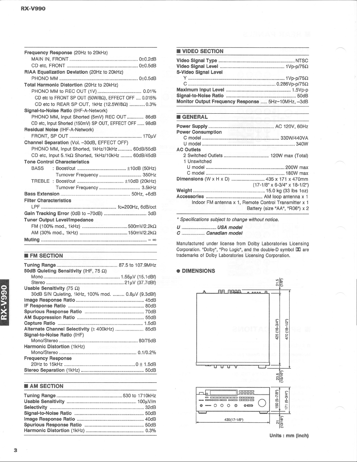
Dimensions (W x H x D) 435 x 171 x 470mm
(17-1/8" x 6-3/4" x 18-1/2")
Weight 15.0 kg (33 Ibs 1oz)
Accessories AM loop antenna x 1
Indoor FM antenna x 1, Remote Control Transmitter x 1
Battery (size "AA", "R06") x 2
• Specifications subject to change without notice.
U USA
model
C
Canadian model
Manufactured under license from Dolby Laboratories Licensing
Corporation. "Dolby", "Pro Logic", and the double-D symbol
DC]
are
trademarks of Dolby Laboratories Licensing Corporation .
• DIMENSIONS
~~
A
Illl
~J..ILU.
n
~~
~
:b
'"
0
~
r-
oq
U U
V
1-..-1
"''''
g3~
...rJn
=
~
'"
~
=
=
~~
__ CCCCc:::::::::I C~ DCt::::::::l
~t=:J
0
0-0
00
Cll>
O~
0
G
'!!
~
435(17-1/8") -~
N£
Units: mm (InCh)
-...------ I
RX-V990
• DISASSEMBLY PROCEDURES
(Remove parts in disassembly order as numbered.)
1. Removal of Top Cover
a. Remove 4 screws (
CD )
and 3 screws (
CI! )
in Fig. 1.
2. Removal of Bottom Cover
a. Remove 11 screws ( ® ) in Fig. 1.
3. Removal of Front Panel
a. Remove 5 knobs.
b. Remove 6 screws ( ® ) in Fig. 1.
Front Panel
----.......J
• DIAGNOSTIC MODE
PURPOSE OF DIAGNOSTIC MODE
•If the protection circuit operates to turn OFF the
POWER when the POWER is turned ON, the cause can
be found out by starting the DIAGNOSTIC mode. (Pro-
tection message)
• Some items of the DIAGNOSTIC menu facilitate opera-
tion check, inspection and measurement.
HOW TO START DIAGNOSTIC (DIAG.)
Turn on the POWER key while pressing
ClO
PRO LOGIC
and 70mm MOVIE THEATER keys simultaneously, and
then the DIAG. mode is started.
HOW TO CANCEL DIAG.
Turning off the POWER key of the front panel or pressing
the CHURCH key of the remote control transmitter will
restore the normal operation and DIAG. will be canceled.
•To keep the setting stored in the memory, be sure to
check that DIAG. No. 7 is set to "KEEP DATA" before
canceling DIAG. DIAG. No.7 is set to "KEEP DATA"
when starting DIAG.
Top Cover
Bottom Cover
Fig. 1
Monitor Display
DIAG VER.·· ....
1. MAIN BYPASS
2. FRONT RAM THR
3. MAIN DSP THR
4. EFCT OFF/DISP
5. MANUAL TEST
6. PRO LOGIC
7. FACTORY PRESET
8. AD CHECK MODE
The menu of the DIAGNOSTIC mode is displayed on
the monitor display and kept as it is untill canceled.
4
RX-V990
CONTENTS OF DIAG. OPERATIONS
• DIAG. MENU can be selected by pressing the PRESET
STATIONS key of the front panel or PROGRAM key of
the remote control transmitter.
• Each DIAG. MENU has a SUB-MENU. Every time the
same key, PRESET STATIONS key of the front panel or
PROGRAM key of the remote control transmitter is
pressed, another SUB-MENU is selected.
• While the diagnostic mode is set, function of power on/
off, selecting an input source, adjusting master volume
and effect level are available.
• The contents of each DIAG. MENU are as follows.
No. DIAG. Menu Sub Menu
1
MAIN BYPASS EFFECT LEVEL 60 (-10dS)/80 (OdS)
2
FRONT RAM THR EFFECT LEVEL 60 (-10dS)/80 (OdS)
3
MAIN DSP THR EFFECT LEVEL
100 (+10dS)/60 (-10dS)/80 (OdS)
4
EFFECT OFF/DISP EFFECT OFF/DISPLAY CHECK
5
MANUAL TEST TEST: LEFT/CENTER/RIGHT/SUR
6
PRO LOGIC CENTERNORMAUCENTERWIDE/CENTER
PHANTOM/BYPASS/CINEEO.ON (Note1)
7
FACTORY PRESET KEEP DATNFACTORY PRESET
8
AD CHECK MODE KEY AD
&
OTHER AD CHECK
9
EXIT (Note 2)
-
Note
1:
CI N E EO ON appears but such function is not
provided.
Note 2: No.9 menu item is available only through the
remote control.
5
FL DISPLAY
When the DIAGNOSTIC mode is set, the initial display
appears on the FL display followed by the DIAGNOSTIC
display (No.1).
The initial display can be redisplayed by pressing the AlB/
C/D/E key (but not when performing AD check by using
DIAG. No.8).
• Components of initial display (Example)
[3= ~CJ 40
t t
RXV990U
**
t t
Protection AD
Message value
Model &ROM
Market version
[Protection message]
When the protection function activated, the protection mes-
sage is displayed and the power is turned off.
Instantly ~ "1 I"
After about 0.5 seconds ~ "2 PS"
After about 2 seconds - "3 DC"
Correct the faulty part according to the protection message.
Protectionmessage Cause
1 I Anabnormalcurrentflowedto the poweramplifier.
2PS Abnormalconditionoccurredin the powersection.
3 DC DCis detectedinthe outputof the poweramplifier.
[AD value to Model
&
Market relation]
AD value (+3) Model
&
Market Remarks
10 RXV990 R
**
R : General model
40 RXV990 U" UC : USA
&
Canadian models
40 RXV990 A
**
A : Australian model
70 RXV990 L" G : European model
• Components of DIAGNOSTIC display
1
DIAG.tmenu
CD
+
MAIN BYP 60
operat{on display
Input source
No.
*Supplement
When in the DIAG. mode, lighting of all segments of
the tuning meter for catalogue photographing can be
reserved by using the EFFECT key. (Do not use this
function as it is not intended for servicing.)
With such reservation made, all segments of the tun-
ing meter light when the tuner function is selected in
the normal mode. (This reservation is effective once
only at the next POWER ON. After that, normal meter
operation is provided.)
Content FL display
Reservation of full scale T-METER ON
Reservation of normal T-METER OFF
------------------------------
HOW TO USE DIAG. MODE
In order to confirm characteristics (specifications)
listed in the table below, use DIAG. No.1, 3 and 4.
(For specifications, refer to page 3.)
No. Items
1
• Output Level/Impedance
• Frequency Response
•SIN
3
• Minimum RMS Output Power Per Channel (Center &
Rear)
• Total Harmonic Distortion (Center &Rear)
• Minimum RMS Output Power Per Channel (Front)
4• Dynamic Power
• Power Bandwidth
• Damping Factor
• Input Sensitivity/lmpedance
• Headphone Jack Rated Output/Impedance
• Channel Separation
• Total Harmonic Distortion (Rec Out &Front)
• Tone Control Characteristics
CONTENTS OF DIAGNOSIS
MAIN BYPASS
• MAIN UR is output through the bypass.
• CENTER is output with the steering off and at (L + R)/2.
• RURR is output by way of PS-RAM at DSP through.
• Electric volume for both the CENTER & REAR is
changeable by changing the SUB-MENU.
Sub-menu FL display
Center &Rear
E. Volume -10dB 1 (Input source) MAIN BYP 60
Center &Rear
E. Volume OdB 1 (Input source) MAIN BYP 80
L
I
YSS223
L
DOLBY PRO LOGIC section
+~lzr~~----
C
~
DSPsection
c.t&-
,
RL
,
,
,
,
.- RR
t
PS-RAM •
,,
,
,
----- ______ 1
R
RX-V990
FRONT RAM THR
L
C(L+R)12 L
R
R
RL
RR
• CENTER is output with the steering off and at (L + R)/2.
• RURR is output by way of PS-RAM at DSP through.
• FUFR is output by way of PS-RAM to MAIN UR at
DSP through.
• Electric volume for both the CENTER & REAR is
changeable by changing the SUB-MENU.
Sub-menu FL display
Center
&
Rear
E. Volume -1 OdB 2(Input source) FRNT THR 60
Center
&
Rear
E. Volume OdB 2(Input source) FRNT THR 80
YSS223
L
DOLBY PRO LOGIC section
+~tzr~~----
,.-
C
,.....
DSP section
--
FL
t...,1+-
,
FR
-
,
•
,
+
,
RL
,
,
,
.-
RR
t
PS-RAM •
,
,
,
-----------"
RL
RR
R
L
C (L+R)/2
R
MAIN DSP THROUGH
• MAIN UR is output through the PRO LOGIC.
• CENTER is output with the steering off and at (L + R)/2.
• RURR is output by way of PS-RAM at DSP through.
• Electric volume for both the CENTER & REAR is
changeable by changing the SUB-MENU.
Sub-menu FL display
Center &Rear
E. Volume +10dB 3 (Input source) MAIN DSP100
Center &Rear
E. Volume -10dB 3 (Input source) MAIN DSP60
Center &Rear
E. Volume OdB 3 (Input source) MAIN DSP80
YSS223
DOLBY PRO LOGIC section
__.-_nn ____
;~~Z~~~----
C
--.-----------
DSP section
'+EI7-
,
RL
,
,
,-
,,
,
.-
RR
t
PS-RAM •
,
,
,
,
----- ______ 1
L
C(L+R)12
R
RL
RR
6
RX-V990
EFFECT OFF & DISPLAY CHECK
o
Effects always off in this menu.
o
All segments of the FL are displayed.
Sub-menu FL display
EFFECT OFF 4 (Input source) EFFECT OFF
FULL SEGMENT DISPLAY -FULL SEGMENTDISPLAY-
MANUAL TEST TONE
o
Every time PRESET key NO.5 is pressed, the TEST
TONE shifts and is output.
o
CENTER MODE is WIDE.
o
Electric volume for both the CENTER &REAR is 60
HOdB).
Sub-menu FL display
LEFT 5 (Input source) TEST LEFT
CENTER 5 (Input source) TEST CENTER
RIGHT 5 (Input source) TEST RIGHT
SURROUND 5 (Input source) TEST SUR
o
The auto input balance which is on in the normal mode
is turned off (PRO LOGIC).
o
Electric volume for both the CENTER and REAR is 60
(-10dB).
oIn the SUB-MENU of CINEMA EQ ON, CENTER
MODE is WIDE.
Center Mode NORMAL 6 (Input source) PRO LOGIC
Center mode WIDE 6 (Input source) PRO LOGIC
Center mode PHANTOM 6 (Input source) PRO LOGIC
EFFECT OFF 6 (Input source) BYPASS
Sub-menu I FL display
CINEMA EQ ON
I
6 (Input source) CINE EQ ON
Note) CINE EQ ON appears but such function is not pro-
vided.
11~llil
FACTORY PRESET
o
Reservation of the initializing DATA of the BACK-UP
RAM.
o
Then with the POWER key turned off after selecting
the SUB-MENU, FACTORY PST, all RAM DATA is
initialized.
Sub-menu
Keeping on RAM DATA
Initializing RAM DATA
7
CAUTION: Before setting to the FACTORY PRESET,
write down the existing preset memory con-
tent of the Tuner in a table as shown below.
(This is because setting to the FACTORY
PRESET will cause the user memory con-
tent to be erased.)
Preset group
P1 P2 P3 P4
A
B
C
D
E
Preset group
P5 P6 P7 P8
A
B
C
D
E
• Factory Preset
1) SURROUND section
DELAY TIME : [][] PRO LOGIC
: ENHANCED
: MOVIE THEATER
:TV THEATER
: SPORTS
: STADIUM
: ROCK CONCERT
: JAZZ CLUB
: CHURCH
: CONCERT HALL
CENTER MODE : NORMAL
EFFECT LEVEL : CENTER
: REAR
80
80
20ms
20ms
17ms
28ms
20ms
45ms
22ms
26ms
40ms
30ms
2) SELECTOR section
INPUT
VIDEO (BGV)
SURROUND PROGRAM
3) TUNER section
: CD
: LD/TV
:[][] PRO LOGIC
Preset group
P1 P2 P3 P4
A/C/E
87.5MHz 90.1MHz 95.1MHz 98.1MHz
530kHz
BID 1080kHz 1440kHz (U, C, R)
630kHz 531kHz
(R,A, G)
Preset group
P5 P6 P7 P8
107.9MHz 107.9MHz
A/C/E
(U, C, R) 88.1MHz 106.1MHz (U, C, R)
108.0MHz 108.0MHz
(R,A,G) (R, A, G)
1710kHz 1400kHz
BID (U, C, R) 900kHz 1350kHz (U, C, R)
1611kHz 1404kHz
(R,A, G) (R,A, G)
For all the above, AUTO TUNING and AUTO STEREO are
selected as the TUNING mode.
RX-V990
f
I<DIAG8
i
AD DATA CHECK
•In this MENU, it is possible to check the several AD data .
• The AD data is a percent unit, about 2.8V is equal to 100% only for tuning meter, about 5V is equal to 100% for the others.
Sub-menu FL display
Normal DIAG. mode
8
(Input source) AD CHK MODE
PAGE 1 :
P 1 99
99 99 99 99
KEY AD DATA
AD check
CH
0
CH
1
CH 2
CH
3
CH
4
page No.
PAGE 2 :
P2
40
52
07
2 1
70
OTHER AD DATA
AO check
REC OUT TUNING PROTECTION PROTECTION OTHER SWITCH
page No.
METER I
2
•In PAGE1, it displays the AD data of the keys, in PAGE2, the others .
• When in the PAGE1 or PAGE2 sub-menu, it is not possible to operate the menu of DIAG. No. 1-7.
Table
for checking
AD DATA.
AD Data Key AD Data (Page1) Other AD Data (Page2)
%
(±3) REC OUT Other switch
CHO CH1 CH2 CH3 CH4 VIDEO TYPE FREQUENCYSTEP
00 CENTERMODE PRO LOGIC 70mm MOVIE: AUX AUX 100/10kHz
10 PRESET ST. 7TUNING UP ENHANCED TV THEATER VCR2 VCR2 S1 5019kHz
20 PRESET ST.
6
TUNINGDOWN LEVEL UP SPORTS VCR1 VCR1 100/10kHz
30 PRESET ST. 5FM/AM LEVEL DOWN STADIUM LDITV LDITV S2 5019kHz
40 PRESET ST.
4
AUTO/MAN'L LEVEL REAR EFFECT PHONO SOURCE 100/10kHz
50 PRESET ST.
3
EDIT LEVELCENTER CONCERTHALL CD TAPE 1S1 5019kHz
60 PRESET ST. 2MEMORY
-
CHURCH TUNER TUNER 100/10kHz
70 PRESET ST. 1SPEAKER BDELAY UP JAZZ CLUB TAPE 1 CD S2 5019kHz
80 PRESETPAGE SPEAKER A DELAY DOWN ROCKCONCERTTAPE
2
MONITOR PHONO
--
90 KEY OFF STATE
-
99 KEY OFF STATE
---
Kind of the. protection (Page2) AD OAT A of normal
Protection 1 1-13
(DC is detected in power amp)
Protection 2 15-29
(Abnormal condition in power section)
Note)
• There is no U, C or A model for
S1/S2.
•S1 : R model (internal synchronization is NTSC type.)
G model (internal synchronization is PAL type.)
•S2 : R model (internal synchronization is prohibited.)
G model (internal synChronization is PAL type.)
8
IRX-V990
MP ADJUSTMENTS
• Idling Current Adjustment (FRONT)
1) No signal applied.
2) Non-loaded condition.
3) Aging is not neccessary.
Item Test Point Adjusted points Rating (~C)
FRONT LR694 or R695 VR601 3.0mV-3.5mV
FRONT R R707 or R708 VR602
'Confirm that the idling current (FRONT) is 6mV-12mV
after 60 minutes.
8 Confirmation of Idling Current (CENTER)
1) No signal applied.
2) Non-loaded condition.
3) Aging is not neccessary.
Note)
• Q617 and Q626 are transistors(2SC1846S) for tem-
perature correction. Apply silicone grease to contact
surface with the heat sink.
Item Test Point Rating
(~C)
Note
If the measured vOltage exceeds 6.1mV, cut the
CENTER R720 0.1mV-6mV lead wires of R682 and then check again if each
measured value satisfies the rating.
Note)
•If R682 has already been cut off and idling current does not flow, reconnect R682.
• Q633 is the transistor(2SC1846S) for temperature correction. Apply silicone grease to
contact surface with the heat sink.
R708
VR602
rl-
R720
br ~
t- -•
.
.
.
VR601 R707
r
R682
9
R694 or R695
R707 or R708
R720
FCUIOFF
'M'u