Nissin WR02 User manual

株式会社日新テクニカ
ホームページ:http://www.nissin-tech.com メール:[email protected]
1
WR02 シリアル(RS232)
WiFi ルーター
変換器
株式会社日新テクニカ
http://www.nissin-tech.com
2014/8/2
copyright@2014


株式会社日新テクニカ
ホームページ:http://www.nissin-tech.com メール:[email protected]
3
1 Brief Introduction.............................................................................................................5
2 Summarize.........................................................................................................................7
2.1 Technical Specifications ................................................................................................7
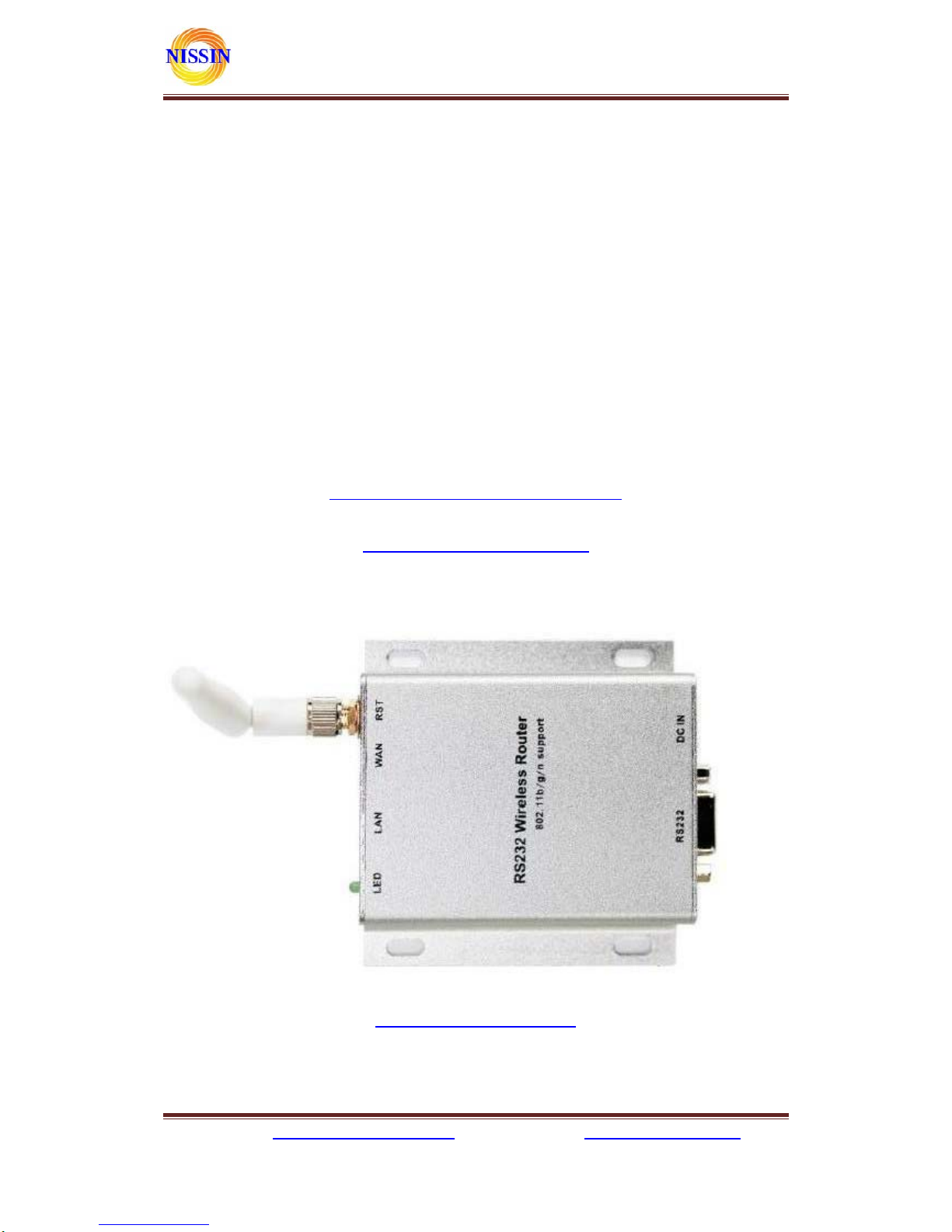
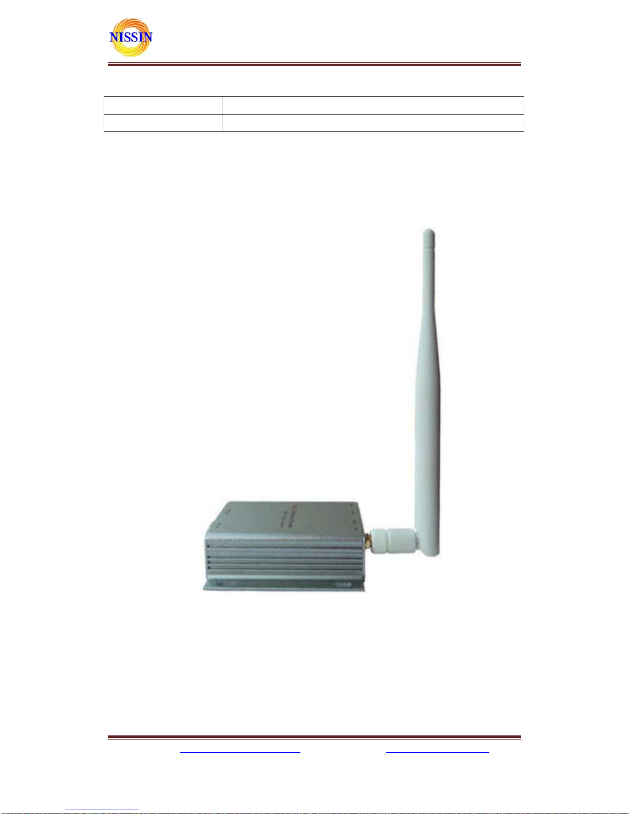
2.2 Product Outline............................................................................................................8
2.3 External Interface.........................................................................................................8
2.3.1 RS232 ....................................................................................................................9
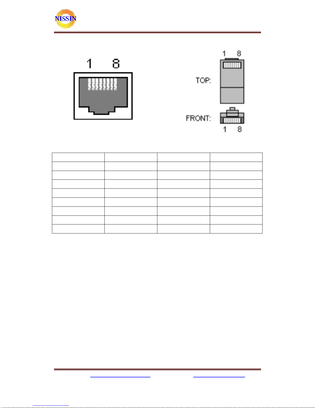
2.3.2 LAN Interface and WAN interface..........................................................................9
2.3.3 RST Button..........................................................................................................10
2.3.4 5V Power Input....................................................................................................10
2.3.5 Antenna Terminal.................................................................................................10
2.3.6 LED Indicator light.............................................................................................. 11
3 Networking mode Brief Introduction ................................................................................ 11
3.1 Star like Network Structure ........................................................................................ 11
3.3 Bus Network structure................................................................................................ 12
3.4 Peer-to-peer Network structure...................................................................................13
4 Quick start Guide............................................................................................................. 14
4.1 Preparatory work.......................................................................................................14
4.2 Power-up Test.............................................................................................................14
4.3 Function Test.............................................................................................................. 15
5 Product parameter configuration and instruction..............................................................16
5.1 Serial Server Logo in.................................................................................................. 16
5.2 Serial server Parameter inquiry..................................................................................16
5.3 WEB network configuration .......................................................................................17
5.3.1 Serial to Ethernet-dynamic ip...............................................................................18
5.3.2 Serial to Ethernet-static ip....................................................................................18
5.3.3 Serial to WIFI CLIENT-dynamic ip...................................................................... 18
5.3.4 Serial to WIFI CLIENT-static ip........................................................................... 19
5.3.5 Serial to WIFI AP.................................................................................................19
5.4 WEB serial configuration............................................................................................ 19
5.5 Submitting Alteration ................................................................................................. 20
6 Function Description ........................................................................................................ 21
6.1 Serial to Ethernet .......................................................................................................21
6.2 Serial to WIFI CLIENT.............................................................................................. 21
6.3 Serial to WIFI AP.......................................................................................................22
6.4 Default mode..............................................................................................................22

株式会社日新テクニカ
ホームページ:http://www.nissin-tech.com メール:[email protected]
4
6.4.1 TCP Server .......................................................................................................... 23
6.4.2 TCP Client ........................................................................................................... 23
6.4.3 UDP Server ..........................................................................................................24
6.4.4 UDP Client...........................................................................................................24
7 Typical application example..............................................................................................25
7.1 Active Serial devices connected to the Internet ............................................................25
7.1.1 Application scenarios............................................................................................25
7.1.2 Reference setting (UsingAccess ControlAttendance Machine as an example)........ 25
7.1.3 Reference Setting figure........................................................................................ 26
7.2 Passive serial devices connected to the Internet ...........................................................26
7.2.1 Application scenarios............................................................................................26
7.2.2 Reference setting (Take sensor as an example)....................................................... 27
7.3 Equivalent serial devices connected to the Internet......................................................28
7.3.1 Application scenarios............................................................................................28
7.3.2 Reference setting..................................................................................................28
8 Setting for Peer-to-peer (P2P)..........................................................................................30
8.1 Get UUID...................................................................................................................30
8.2 Send/Receive data....................................................................................................... 30
8.2.1 P2Pto open the website of the serial server ........................................................... 30
8.2.2 Transfer data by P2P............................................................................................31
※ 使用されたソースコードはhttp://www.nissin-tech.com/
からダウンロードできます。
※ この文書の情報は、事前の通知なく変更されることがあり
ます。
※ (株)日新テクニカの書面による許可のない複製は、いかな
る形態においても厳重に禁じられています。

株式会社日新テクニカ
ホームページ:http://www.nissin-tech.com メール:[email protected]
5
1 Brief Introduction
This product is based on the universal serial interface network standard, built-in TCP/IP
protocol stack, enabling the user serial port, Ethernet, wireless network (WiFi) interface between the
conversions.
Through the serial server, the traditional serial devices do not need to change any configuration;
data can be transmitted through the Internet network. Provide a quick solution for the user’s serial
devices to transfer data via Ethernet.


株式会社日新テクニカ
ホームページ:http://www.nissin-tech.com メール:[email protected]
7
2 Summarize
2.1 Technical Specifications
wireless:IEEE 802.11n、IEEE 802.11g、IEEE 802.11b
Network standard
wired:IEEE 802.3、IEEE 802.3u
Wireless transmission rate 11n: maximum up to 150Mbps
11g: maximum up to 54Mbps
11b: maximum up to 11Mbps
Tracks number 1-14
Frequency range 2.4-2.4835GHz
Emission power 12-15dBm
Interface WAN LAN, RS232, DC IN,ANTENNA
Antenna External Antenna 6dB
Functional Parameters
WIFI work mode Client/AP/Router(default), default WiFi password: 12345678
WDS Function Support WDS wireless bridge connection
Wireless MAC address filtering
Wireless security function switch
64/128/152 bit WEP encryption
Wireless security
WPA-PSK/WPA2-PSK、WPA/WPA2 security mechanism
Remote Web management
Configuration file import and export
Network management
WEB software upgrade
Serial to Ethernet
Maximum transmission
rate
500000bps
TCP connection Max connection number > 20
UDP connection Max connection number > 20
Serial baud rate 1200~500000bps
Other Parameters
Status indicator Status indicator
Operating temperature:-20~70℃
Operating humidity:10%~90%RH(non condensing)
Storage temperature:-40~80℃
Environmental standard
Storage humidity:5%~90%RH(non condensing)

株式会社日新テクニカ
ホームページ:http://www.nissin-tech.com メール:[email protected]
8
Additional properties Frequency bandwidth optional:20MHz,40MHz,Automatic
2.2 Product Outline
The outline of the serial WIFI server as follows. Mechanical Dimensions:
85×85×25 mm, not including the antenna.
2.3 External Interface
The serial WiFi sever is a serial-WiFi-Ethernet device, its external interface including RS232,
DC IN, LAN, WAN, LED, RST. This section will detail the definition of each interface.

株式会社日新テクニカ
ホームページ:http://www.nissin-tech.com メール:[email protected]
9
2.3.1 RS232
The following figure shows a schematic diagram of the external interface of RS232. Interface,
the definition is as follows:
No Function Direction Explanation
1 NC NC None
2 RxD Input Data receiving input
3 TxD Output Data sending output
4 NC NC None
5 GND Input GND
6 NC NC None
7 NC NC None
8 NC NC None
9 NC NC None
2.3.2 LAN Interface and WAN interface
The serial WiFi server provides two network interface, WAN port and LAN port, the interface is
a standard form of RJ-45 interface. RJ-45 interface definition is shown as below:

株式会社日新テクニカ
ホームページ:http://www.nissin-tech.com メール:[email protected]
10
The following table shows the pin definitions of RJ-45:
No Function Direction Explanation
1 TX+ Output Transmit Data+
2 TX- Output Transmit Data-
3 RX+ Input Receive Data+
4 NC NC
5 NC NC
6 RX- Input Receive Data-
7 NC NC
8 NC NC
2.3.3 RST Button
RST button is used to reset HLK-WR02 Server to the factory settings. METHODS: When the
device have startup complete, then using sharp object to press the RST button for at least 10 seconds,
all parameters of the server can be set to the default value.
2.3.4 5V Power Input
Voltage range: 4.5 ~ 5.5V. The default configuration of the Device for the power adapter is
5V/1A DC power supply. Power interface: the inner core is positive.
2.3.5 Antenna Terminal
Standard SMA interface within the outer spiral needle, the interface can be equipped with 2.4G
SMA antenna inside the screw hole standard.

株式会社日新テクニカ
ホームページ:http://www.nissin-tech.com メール:[email protected]
11
2.3.6 LED Indicator light
Status indicating:
LED light blink:WiFi is ok
LED light off :WiFi is not ok
3 Networking mode Brief Introduction
This section focuses on describing application of the device. To introduce sorts of related
networking scenarios.
3.1 Star like Network Structure
The most basic network structures of the serial server is the star network topology. This kind of
network topology are also common in the local area network (LAN), a network topology. Its main
characteristic is through a network of each workstation nodes in the network equipment
concentration equipment (such as a hub or switch) together, are distributed in each node satellite.
This kind of network structure is more convenient in the equipment increase or decrease. The
following figure describes the Star like Networking structure:

株式会社日新テクニカ
ホームページ:http://www.nissin-tech.com メール:[email protected]
12
In this network structure, each terminal work as an independent node to connect to the server.
The server can commune with each terminal by way of TCP or UDP. To achieve all of the serial port
terminal is connected to the Internet.
3.3 Bus Network structure
The character of Bus networking structure is that all the devices are directly connected to one
bus, which is a set of network with low cost. However, all the devices in the network share the
bandwidth of the bus, therefore, the network transmission rate will decline along with the increase in
user. RS - 485 bus structure is typical sample of this structure. The bus structure diagram is as
follows:

株式会社日新テクニカ
ホームページ:http://www.nissin-tech.com メール:[email protected]
13
In such a network structure, all the equipment through the same cable connect to the server.
Network maintenance and extension of relatively is easier, the response speed of the equipment and
network transmission rate is less than star bus structure.
3.4 Peer-to-peer Network structure
Using the Device, original serial device can be connected to peer-to-peer network structure. The
characteristic of this structure is that all the devices in the network status are equal. For user’s
equipment, there does not exist master-slave relationship or a managed device. All user terminals can
be equivalent to send and receive data. The structure diagram is as follows:

株式会社日新テクニカ
ホームページ:http://www.nissin-tech.com メール:[email protected]
14
Using the serial server, user’s serial devices can be equivalent to connected to the Ethernet.
Thus, to achieve peer-to-peer communications through Ethernet.
4 Quick start Guide
This section describes how to manage to use the device as soon as possible, users can become
familiar with the major operations quickly with the serial server, according to the introduction of this
section.
4.1 Preparatory work
zHardware
The serial server and matching power supply
Ethernet cable
Direct serial line
zSoftware
Serial Debug software, such as serial port Debug assistant, serial master and so on.
TCP/UDP Debug software
4.2 Power-up Test
1. Power up the serial server. The Link light will flick at low frequency after power.
2. Connected the serial server with WIFI or network cable (or you can connect the PC and the
serial server in the same LAN through hub or router).
3. The IP address of the PC should be set to 192.168.16.X. The default IP address of the Serial

株式会社日新テクニカ
ホームページ:http://www.nissin-tech.com メール:[email protected]
15
Server is 192.168.16.254
4. Make sure the PC side can ping the serial server.
4.3 Function Test
1. Power on the device, Connect the RS232 and the internet, make sure you PC can ping
192.168.16.254:
2. Start the serial Debug software,we use Serial&TCP_UDPTool.exe in this sample;
3. Start a TCP client like the below:

株式会社日新テクニカ
ホームページ:http://www.nissin-tech.com メール:[email protected]
16
5 Product parameter configuration and instruction
The serial server has built-in Web Server, users can configure the parameters of the serial server
via web pages. Also, you can logo in to the website to see the current serial server parameter
settings.
5.1 Serial Server Logo in
When you have enter the web sit, you needs to change the password to avoid non-administrator
rewritten it illegally. The default user Name and password of the serial server are admin/admin.
Please rewrite the password after first use.
Note:The serial server only provide user login password setting. Please keep the rewritten
password firmly in mind.
5.2 Serial server Parameter inquiry
After passing the IE browser to log in to the serial server, you can see the screen shown below.
This page shows the main current operating parameters of serial server.

株式会社日新テクニカ
ホームページ:http://www.nissin-tech.com メール:[email protected]
17
Through the correct module address (default address:http://192.168.16.254),you can access to
the WEB configuration page.
The page can be divided into 3 areas:
1. Network configuration area
2. Serial function configuration areas
3. Configuration submit area
5.3 WEB network configuration
Net mode selection:
Default – default work mode
ETH-SERIAL – Serial to Ethernet
WIFI (CLIENT)-SERIAL – serial to WIFI CLIENT
WIFI (AP)-SERIAL) – Serial to WIFI AP

株式会社日新テクニカ
ホームページ:http://www.nissin-tech.com メール:[email protected]
18
Choose different work mode, the web will show you different page. Mode configuration page is
as follows:
5.3.1 Serial to Ethernet-dynamic IP
5.3.2 Serial to Ethernet-static IP
5.3.3 Serial to WIFI CLIENT-dynamic IP

株式会社日新テクニカ
ホームページ:http://www.nissin-tech.com メール:[email protected]
19
5.3.4 Serial to WIFI CLIENT-static IP
5.3.5 Serial to WIFIAP
5.4 WEB serial configuration
Serial Web configuration page(Serial2Net.asp)is as follows:

株式会社日新テクニカ
ホームページ:http://www.nissin-tech.com メール:[email protected]
20
Current shows the current configuration. Updated shows the current revision parameters, Submit
submit the revision.
Serial Configure:Serial configuration format:Baud rate, data bits, parity bit, stop bit. For
example:“115200,8,n,1”.
Serial Framing Length:The Length of Serial Framing
Serial Framing Timeout:The time of Serial Framing
Network Mode:choose Client、Server or none
Remote Server Domain/IP:Remote Server Domain/IP address, For example:192.168.11.245 or
www.nissin-tech.com .
Locale/Remote Port Number:The specified parameter is not the same under the different network
modes. Client specifies the port number on the remote, Server specified local port number.
Network Protocol:Use TCP or UDP Protocol
Network Timeout:Under the server network mode, no data transmission within the timeout period,
the connection will be disconnected. 0 specifies never disconnected.
5.5 Submitting Alteration
Click the button ‘Apply’ to submit the configuration of the current page. If some parameters of
Table of contents
Popular Wireless Router manuals by other brands

SoftBank
SoftBank 601HW Start guide

D-Link
D-Link DI-524 - AirPlus G Wireless Router Quick installation guide

TRENDnet
TRENDnet TEW-813DRU user guide

Gree
Gree GWH09KF-K3DN series installation manual

Abocom
Abocom Bluetooth USB Dongle UBT3KH Specification sheet

D-Link
D-Link AirPlusXtremeG DI-624 Quick installation guide