Nissindo MA350 User manual

Congratulation &
Thank You for
Purchasing
Nissindo
Products!
OPERATING INSTRUCTIONS
PROFESSIONAL KARAOKE MIXING AMPLIFIER
MA-350
Thank you for purchasing this unit. To
make full and effective use of this unit,
please read this Owner's Manual
carefully before operating it. Please
retain this manual for future reference.
w w w . N i s s i n d o U S A . c o m
MI C MASTER VOLUME MU SIC VO LUME
#MPX VOCAL AID
b
VCD
INPUT SE LECTION
AUX
LD DVD
b4 #4
LD
b3 #3
DVD
b2
VOCAL
AID
#2
VCD
b1
MPX
#1
AUX
16 BI T DI GI TAL K EY CO NT RO LL ER
P r o f e s s i o n a l K a r a o k e S y s t e m
KEY
MI C TONEMI C VOLUME
MI C 1 MI C 2 MI C 3
MU SIC T ONE
BAL A NCE B ASS TREBLEBASS TREBL E DEL AY
EC HO EFF ECT
RE PEAT EC HO
POW ER
OF F ON 18
17
0 20
1 19
2
3
4 16
5 15
6
789 11 12 13
10
14
18
17
0 20
1 19
2
3
4 16
5 15
6
789 11 12 13
10
14
MI C INPUT
1 2 3
MANUAL
MI C MASTER VOLUME MU SIC VO LUME
#MPX VOCAL AID
b
VCD
INPUT SE LECTION
AUX
LD DVD
b4 #4
LD
b3 #3
DVD
b2
VOCAL
AID
#2
VCD
b1
MPX
#1
AUX
16 BI T DI GI TAL K EY CO NT RO LL ER
P r o f e s s i o n a l K a r a o k e S y s t e m
KEY
MI C TONEMI C VOLUME
MI C 1 MI C 2 MI C 3
MU SIC T ONE
BAL A NCE B ASS TREBLEBA SS TR EBL E DELAY
EC HO EFF ECT
RE PEAT EC HO
POW ER
OF F ON 18
17
0 20
1 19
2
3
4 16
5 15
6
789 11 12 13
10
14
18
17
0 20
1 19
2
3
4 16
5 15
6
789 11 12 13
10
14
MI C INPUT
1 2 3
STEREO MIXING AMPLIFIER MODEL: MA-3 5 0
2
CONTENTS
INTRODUCTION............................................................................................................................................... 3
SYSTEM FEATURES........................................................................................................................................... 3
SAFETY INSTRUCTIONS............................................................................................................................. 4~6
PACKAGE ACCESSORIES................................................................................................................................ 6
SYSTEM APPLICATIONS.................................................................................................................................. 8
• Connecting the Main Speaker........................................................................................................................... 8
• Connecting the Audio/Video Input Source....................................................................................................8
• Connecting the Video Output Source..............................................................................................................9
• Connecting the Audio Output Source..............................................................................................................9
• Connecting the Audio/Video Input Source.................................................................................................10
• Connecting the Microphone Input..................................................................................................................11
CONTROLS AND FUNCTIONS.................................................................................................................... 12
• Remote Control.......................................................................................................................................................12
• Front Panel................................................................................................................................................................13
• Rear Panel................................................................................................................................................................14
OPERATING INSTRUCTIONS....................................................................................................................... 15
PHYSICAL DIMENSIONS............................................................................................................................... 16
SPECIFICATIONS..............................................................................................................................................16
TROUBLESHOOTING................................................................................................................................17~18
FINAL WORDS TO USER............................................................................................................................... 18
WARRANTY...................................................................................................................................................... 19
AGENCY REGULATORY NOTICES.............................................................................................................. 20
CONTACT INFORMATION............................................................................................................................ 21
Features
Intro
Amplifier
Operating
Safety
Applications
Package
Final Words
Spec
Troubleshooting
Dimensions
Warranty
Notices
Contact Us

3
Features
SYSTEM FEATURES
STEREO MIXING AMPLIFIER
• Master Music Volume Control
• Master Microphone Volume Control
• Remote Control and line out for the wired control system
• Source inputs LD, VCD, CDG, AUX
• Music speed key control
• Built-in Super Quiet Fan
• 3 Microphone Inputs in the front panel
• Music Tone Control: Balance, Bass, Treble
• Microphone Tone Control: Bass, Treble
• Digital Echo Control: Echo, Delay, Repeat
• 4 channels speaker outputs
• AC-power switch able 110V~240V, 60Hz~50Hz
Intro
INTRODUCTION
Based on our observations and borrowing the proven design
of Karaoke equipment in Asia, Nissindo has been constantly
improving and developing state-of-the-art Karaoke
technologies to satisfy the specific needs of the consumers in
North America. Therefore, we have successfully designed
both commercial and home entertainment Karaoke equipment
for the North America consumers.
Thank you for choosing Nissindo Mixing Amplifier MA-350.
We appreciate your vote of confidence in this product. Our
talented engineering team has many years of experience in
audio equipment design.
The MA-350 Mixing Amplifier was a breakthrough in the
karaoke industry. It is the original. It was the flagship as the
very first generation mixing amplifiers for Nissindo. Whether
in quality or sales, the MA-350 Mixing Amplifier was a great
success. It was and still is one of the most reliable mixing
amplifiers for karaoke systems.
Now the MA-350 Mixing Amplifier is regarded as the
traditional amplifier with traditional designs with its 4 music
inputs and microphone/music lock. It became the blueprint
for all future Nissindo Mixing Amplifiers. It features the now
standard 9-Steps Music Key Control for accommodating
each individual’s tonal capabilities and uses Smart Quiet Fan
that turns on automatically when the machine senses a high
temperature. Even after so many years since its first release,
the MA-350 Mixing Amplifier is still one of the best selling
amplifiers for Nissindo.
THIS AMPLIFIER INCLUDES THE FOLLOW:
• Amplifier: 1 pc
• Remote Control: 1 pc
• Instructional Manual: 1 pc
• Warranty & Registration Card: 1 pc
Stereo Mixing Amplifier MA-350 Rear View
RL
SAFETY
MARK
USA 020898-1029536-28ITEMNO. D030906
360020112380
MOD EL NO. : MA-350
CALIFORNIA, UNITED STATES OFAMERICA
E-mail: [email protected]
www.NISSINDOUSA.com
ENGINEERED AND DESIGN INU.S.A.
SER IAL NO .
TO REDUCE THE RISK OF ELECTRIC SHOCK, DO NOT
REMOVE COVER. NO USER SERVICEABLE PARTS INSIDE
REFER SERVICING TO QUALIFIED SERVICE PERSONNEL.
CAUTION
RISK OF ELECTRIC SHOCK
DO NOT OPEN
WITHOUT AUTHORIZATION
Stereo Mixing Amplifier MA-350 Front View
#MPX VOCAL AID
VCD
INP UT S ELE CT IO N
AUX
LD DV D
4 #4
LD
3 #3
DVD
2
VOCA L
AID
#2
VCD
1
MPX
#1
AUX
16 BIT D IGITAL K EY CONT ROLLER
P r o f e s s i o n a l Ka r a o k e Sy s t e m
KEY
MI C INP UT MI C TON EMI C VOL UME
MIC 1 MIC 2 MIC 3
MU SIC T ONE
TR EBL EBA SSBA LAN CEBA SS TR EBL E DEL AY
EC HO EF FEC T
REP EAT E CHO
PO WER
OFF O N
MU SIC V OLU ME
0 20
1 19
2 18
3 17
4 16
5 15
6
7
8
9 11
12
13
10
14
ST ER EO MIX ING A MP LI FI ER MODE L: M A- 35 0
1 2 3
MI C MAS TE R VOL UME
0 20
1 19
2 18
3 17
4 16
5 15
6
7
8
9 11
12
13
10
14

4
RISK OF ELECTRIC SHOCK
DO NOT OPEN
CAUTION: TO REDUCE THE RISK OF ELECTRIC SHOCK DO NOT
REMOVE COVER (OR BACK) NO USER-SERVICEABLE PARTS
INSIDE REFER SERVICING TO QUALIFIED PERSONNEL
Safety
AC-POWER CORD INCLUDED120V AC-POWER
Safety
SAFETY INSTRUCTIONS
Please visit our website at NissindoUSA.com for the most
updated information, corrections on errors and changes in
this manual. You may also contact us at toll free at
1-800-318-2218.
1. Read Instructions: All the safety and operation instructions
should be read before this product is operated.
2. Retain Instructions: The safety and operating instructions
should be kept for future reference.
3. Warnings: All warnings on this product in these operating
instructions should be followed.
4. Follow Instructions: All operating and other instructions
should be followed carefully.
5. Water and Moisture: This product should not be used near
water, for example, near a bathtub, washbowl, kitchen sink,
laundry tub, in a wet basement, near a swimming pool,
swamp or salivating St. Bernard dog, etc.
6. Cleaning: Clean only with a dry cloth.
7. Ventilation: This product should be situated so that its
location or position does not interfere with its proper
ventilation. For example, the Component should not be
placed on a bed, sofa, rug, or similar surface that may block
any ventilation openings, or placed in a built-in installation
such as a bookcase or cabinet that may impede the flow of
air through ventilation openings.
8. Heat: This product should be stayed away from heat
sources such as radiators, or other devices producing heat.
9. Power Sources: This product should be connected to a
power supply only of the type described in these operation
instructions or as marked on this product.
10. Power Cord Protection: Power supply cords should be
routed so that they are not likely to be walked upon or
pinched by items placed upon or against them. Please pay
particular attention to cords plugs, convenience receptacles,
and the point where they exit this product.
11. Object and Liquid Entry: Care should be taken so that
objects do not fall on, or liquids are not spilled into this
product.
12. Damage Requiring Service: This product should be
serviced only by qualified service personnel when:
A. The power-supply cord or the plug has been
damaged; or
B. Objects have fallen, or liquid has spilled into this
product; or
C. This product has been exposed to rain; or
D. This product does not appear to operate normally
or exhibits a marked change in performance; or
E. This product has been dropped, or its chassis has
been damaged.
13. Servicing: The user should not attempt to service this
product beyond those means described in this operating
manual. All other servicing should be referred to the Service
Department.
14. To prevent electric shock, do not use this polarized plug
with an extension cord, receptacle or other outlet unless the
blades can be fully inserted to prevent blade exposure.
15. Grounding or Polarization: Precautions should be taken so
that the grounding or polarization means of this product is not
defeated.
16. Power Precaution: Unplug this product during lightning
storms or when unused for long periods of time. Note that this
product is not completely disconnected from the AC power
source when the power switch is in the OFF position.
17. This machine does not exceed the Class A/Class B
(whichever is applicable) limits for radio noise emissions from
digital apparatus as set out in the radio interference
regulations of the US Department of Communications.
AC-POWER SOURCES
This set should be operated only from the type of power
source indicated on the marking label. If you are not sure of
the type of electrical power supplied to your home, consult
your dealer or local power company. For those sets designed
to operate from battery power, or other sources, refer to the
operating instructions.
This unit is designed for use with 120V/60Hz AC. If the area
where you live have different power source, you may need to
use a transformer to convert to 120 Volts AC.
#MPX VOCAL AID
VCD
INPU T SELEC TION
AUX
LD DV D
4 #4
LD
3 #3
DVD
2
VOCAL
AID
#2
VCD
1
MPX
#1
AUX
16 BIT DIG ITAL KEY C ONTRO LLER
Pr o f e s s i o n a l K ar ao k e S y s t e m
KEY
MIC IN PUT MIC T ONEMIC V OLUME
MIC 1 MIC 2 MIC 3
MUSI C TON E
TREB LEBASSBAL ANCEBASS T REBL E DELAY
ECH O EFFECT
REPE AT ECHO
POW ER
OFF ON
MUSI C VOLUM E
0 20
1 19
2 18
3 17
4 16
5 15
6
7
8
9 11
12
13
10
14
STE REO M IXI NG AMP LIF IER MO DEL : MA- 350
1 2 3
MIC M ASTER VO LUME
0 20
1 19
2 18
3 17
4 16
5 15
6
7
8
9 11
12
13
10
14

#MPX VOCAL AID
VCD
INPUT SELEC TION
AUX
LD DVD
4 #4
LD
3 #3
DVD
2
VOCAL
AID
#2
VCD
1
MPX
#1
AUX
16BIT DIGITAL K EY CONT ROLLER
Prof e s s i o n a l Kara o k e Sys t e m
KEY
MICI NPUT MICT ONEMICV OLUME
MIC1 MIC2 MIC3
MUSIC TONE
TREBLEBASSBALANCEBASS TR EBLE DELAY
ECHO EFFECT
REPEAT ECHO
POWER
OFF ON
MUSIC VOLUM E
0 20
1 19
2 18
3 17
4 16
5 15
6
7
8
9 11
12
13
10
14
STEREO MI XING AMP LIFIER M ODEL: M A-350
1 2 3
MICM ASTER V OLUME
0 20
1 19
2 18
3 17
4 16
5 15
6
7
8
9 11
12
13
10
14
#MPX VOCAL AID
VCD
INPU T SELEC TION
AUX
LD DV D
4 #4
LD
3 #3
DVD
2
VOCAL
AID
#2
VCD
1
MPX
#1
AUX
16 BIT DIG ITAL KEY C ONTRO LLER
Pr o f e s s i o n a l K ar ao k e S y s t e m
KEY
MIC IN PUT MIC T ONEMIC V OLUME
MIC 1 MIC 2 MIC 3
MUSI C TON E
TREB LEBASSBAL ANCEBASS T REBL E DELAY
ECH O EFFECT
REPE AT ECHO
POW ER
OFF ON
MUSI C VOLUM E
0 20
1 19
2 18
3 17
4 16
5 15
6
7
8
9 11
12
13
10
14
STE REO M IXI NG AMP LIF IER MO DEL : MA- 350
1 2 3
MIC M ASTER VO LUME
0 20
1 19
2 18
3 17
4 16
5 15
6
7
8
9 11
12
13
10
14
5
OVERLOADING
Do not overload wall outlets, extension cords or convenience
receptacles beyond their capacity, since this can result in fire
or electric shock.
An appliance and cart combination
should be moved with care. Quick
stops, excessive force and uneven
surfaces may cause the appliance and
cart combination to overturn.
Do not place the electronic equipment onto the unstable
table or stand. It is because it would fall easily from the
unstable table or stand,
so it may cause
accident including
personal injuries and
damage the equipment.
Please follow our
instructions to install the
equipment, or you may
hire a professional
technician to handle the
installation for safety
purpose.
Do not place the set on an unstable cart, stand, tripod,
bracket, or table. The set may fall, causing serious injury to
a child or an adult and serious damage to the set. Use only
a cart stand tripod, bracket, or table recommended by the
manufacturer.
For the set with a three-wire grounding type ac plug:
This plug will only fit into a grounding-type power outlet.
This is a safety feature. If you are unable to insert the plug
into the outlet, contact your electrician to have a suitable
outlet installed. Do not defeat the safety purpose of the
grounding plug.
120V AC-POWER
Do not store the electronic equipment near water or area
with moisture such as bathroom, kitchen sink, laundry area
and swimming pool, etc.
Do not transport the electronic equipment by yourself if its
weight exceeds 70 pounds. It is recommended that two
people work together to transport the equipment or by using
hand truck and the like.
Do not place the electronic equipment directly under
sunlight or close to the window. It may cause overheat on
the electronic equipment by the sunlight.
Do not block the openings and vents in the cabinet which
is designed for the ventilation of the electronic equipment.
The blocking may cause overheat in the electronic equipment
because of insufficient circulation of air, so it would damage
the electronic equipment.
X
#MPX VOCAL AID
VCD
INPU T SELECT ION
AUX
LD DVD
4 #4
LD
3 #3
DVD
2
VOCAL
AID
#2
VCD
1
MPX
#1
AUX
16 BIT DIGI TAL KEY CO NTROL LER
Pr o f e s s i o n a l Kar a o k e Sys t e m
KEY
MIC IN PUT MIC TO NEMIC VO LUME
MIC 1 MIC 2 M IC 3
MUSI C TONE
TREBL EBASSBALANC EBASS TREBLE D ELAY
ECHO E FFECT
REPE AT ECHO
POWE R
OFF ON
MUSI C VOLUME
0 20
1 19
2 18
3 17
4 16
5 15
6
7
8
9 11
12
13
10
14
STE REO MIXI NG AMPL IFIER MO DEL: MA- 350
1 2 3
MIC MA STER VO LUME
0 20
1 19
2 18
3 17
4 16
5 15
6
7
8
9 11
12
13
10
14
#MPX VOCALA ID
VCD
INPUT SE LECTI ON
AUX
LD DVD
4 #4
LD
3 #3
DVD
2
VOCAL
AID
#2
VCD
1
MPX
#1
AUX
16BIT D IGITAL K EY CONT ROLLE R
Pro f e s s i o n a l Karao k e S y s tem
KEY
MIC INPU T MIC TONEMIC VOL UME
MIC 1 MIC 2 MIC 3
MUSIC T ONE
TREBLEBASSBALAN CEBASS TRE BLE DELAY
ECHO EFF ECT
REPEAT EC HO
POWER
OFF ON
MUSIC VO LUME
0 20
1 19
2 18
3 17
4 16
5 15
6
7
8
9 11
12
13
10
14
STER EO MIXIN G AMPLIF IER MODE L: MA-3 50
1 2 3
MIC MAS TER VOLU ME
0 20
1 19
2 18
3 17
4 16
5 15
6
7
8
9 11
12
13
10
14
POWER A NTENNA-A CNANNEL-A DISPLAY CNANNEL-B DISPLAY
CHANNEL-A
VOLUME ANTENNA-B
CHANNEL-B
VOLUME
DUALCHA NNEL VHF WI RELESS S YSTEM
RF
AF
FREQ.
5 10 15 20 25 30 35 40
-30 -25 -20 -15 -10 -5 0 PEAK
000.000M
H
Z
MUTE
RF
AF
FREQ.
5 10 15 20 25 30 35 40
-30 -25 -20 -15 -10 -5 0 PEAK
000.000M
H
Z
MUTE

#MPX VOCAL AID
VCD
INPUT S ELECT ION
AUX
LD DVD
4 #4
LD
3 #3
DVD
2
VOCAL
AID
#2
VCD
1
MPX
#1
AUX
16BI T DIGITA L KEY CON TROLL ER
Pr o f e s si o n a l Kara o k e S y s t em
KEY
MIC INP UT MIC TO NEMI C VOLUME
MIC 1 MIC 2 MIC 3
MUSIC T ONE
TREBL EBASSBALANCEBASS TREBLE DEL AY
ECHO EF FECT
REPEAT E CHO
POWE R
OFF ON
MUSIC V OLUME
0 20
1 19
2 18
3 17
4 16
5 15
6
7
8
9 11
12
13
10
14
STER EO MIXI NG AMPLI FIER MOD EL: MA-3 50
1 2 3
MIC MA STER VOL UME
0 20
1 19
2 18
3 17
4 16
5 15
6
7
8
9 11
12
13
10
14
#MPX VO CAL AID
VCD
INPU T SELEC TION
AUX
LD DVD
4 #4
LD
3 #3
DVD
2
VOCAL
AID
#2
VCD
1
MPX
#1
AUX
16 BIT DIGI TAL KEY C ONTROL LER
Pr o f e s s i o n a l Ka r a o k e Sys t e m
KEY
MIC IN PUT MIC TO NEMIC VO LUME
MIC 1 MIC 2 MIC 3
MUSI C TONE
TREB LEBASSBAL ANCEBASS TREBLE DEL AY
ECHO E FFECT
REPE AT ECHO
POW ER
OFF ON
MUSI C VOLUME
0 20
1 19
2 18
3 17
4 16
5 15
6
7
8
9 11
12
13
10
14
STE REO MIX ING AM PLIF IER MOD EL: MA- 350
1 2 3
MIC MA STER VO LUME
0 20
1 19
2 18
3 17
4 16
5 15
6
7
8
9 11
12
13
10
14
6
MA-350
4
3
2
1
#4
#3
#2
#1
MU SI C
VO LU ME
DOWN UP
KE Y CH AN GE
MIC
VO LU ME
HEATER
Do not place the electronic equipment near heat sources
such as stoves, radiators and heaters, etc. Placing the
electronic equipment too near to these heat sources would
result in damaging the equipment and causing fire.
Using the Remote Control Unit
Use the remote control unit by pointing it towards the remote
control sensor on the amplifier. Objects between the remote
control unit and the remote control sensor may prevent proper
operation.
Cautions Regarding the Remote Control Unit
• Do not expose the remote
control unit to shock. In addition,
do not expose the remote control
unit to liquids, and do not place
in an area with high humidity.
• Do not install or place the remote control unit under
direct sunlight. The heat may cause deformation of
the remote control unit.
• The remote control unit may not work properly if the
remote control sensor
on the amplifier is
under direct sunlight
or strong lighting. In
such cases, change
the angle of the lighting
or the amplifier, or
operate the remote
control unit closer
to the remote
control sensor.
SUN X
If the remote control unit is not
functioning, you may need to
change two new batteries.
MA-350
4
3
2
1
#4
#3
#2
#1
MU SI C
VO LUM E
DO WN U P
KE Y CH ANG E
MIC
VO LUM E
Owner's Manual
PACKAGE ACCESSORIES
The Package accessories include a remote control and one
AC power cord. All other accessories mentioned in the
manual for installation purpose are not included. They are
sold separately.
Package
#MPX VOCAL AID
VCD
INPU T SELEC TION
AUX
LD DVD
4 #4
LD
3 #3
DVD
2
VOCAL
AID
#2
VCD
1
MPX
#1
AUX
16 BIT DIG ITAL KEY C ONTRO LLER
Pr o f e s s i o n a l Ka r a o k e Sy s t e m
KEY
MIC IN PUT MIC T ONEMIC VO LUME
MIC 1 MIC 2 MIC 3
MUSI C TON E
TREB LEBAS SBA LANC EBASS TREB LE DEL AY
ECH O EFFECT
REPE AT ECHO
POW ER
OFF ON
MUSI C VOLUM E
0 20
1 19
2 18
3 17
4 16
5 15
6
7
8
9 11
12
13
10
14
STE REO M IXIN G AMPLI FIER M ODEL : MA-35 0
1 2 3
MIC M ASTER VO LUME
0 20
1 19
2 18
3 17
4 16
5 15
6
7
8
9 11
12
13
10
14
X
MA-350
4
3
2
1
#4
#3
#2
#1
MU SI C
VO LUM E
DO WN U P
KE Y CH ANG E
MIC
VO LUM E
AC power cable (6 feet)
United States (2M) to IEC (F)
Battery size: AA (R6 1.5 V)
AA
ALKALINE
BATTERY
AA
ALKALINE
BATTERY
Consumer warranty
and registration card
<Mail in U.S.A. only> Consumers from Canada
can get the warranty card by downloading it
from our website www.NissindoUSA.com.
CUSTOMER SERVICE
29300 Kohoutek Way #150
Union City, CA 94587
U.S.A.
PLAC E
STAMP
HERE
OPERATING INSTRUCTIONS
PROFESSIONAL KARAOKE MIXING AMPLIFIER
MA-350
Thank you for purchasing this unit. To
make full and effective use of this unit,
please read this Owner's Manual
carefully before operating it. Please
retain this manual for future reference.
w w w . N i s s i n d o U S A . c o m
MANUAL
#MPX VOCAL AID
VCD
INPU T SELEC TION
AUXLD DVD
4 #4
LD
3 #3
DVD
2
VOCAL
AID
#2
VCD
1
MPX
#1
AUX
16 BIT DIGI TAL KEY C ONTRO LLER
Pr o f e s s i o n a l Ka r a o k e Sy s t e m
KEY
MIC IN PUT MIC TO NEMIC VO LUME
MIC 1 M IC 2 MIC 3
MUSI C TONE
TREB LEB ASSBALANCEBASS T REBLE D ELAY
ECHO E FFECT
REPE AT ECHO
POW ER
OFF ON
MUSI C VOLUME
0 20
1 19
2 18
3 17
4 16
5 15
6
7
8
9 11
12
13
10
14
STE REO MIX ING AM PLIF IER MO DEL: M A-35 0
1 2 3
MIC MA STER VO LUME
0 20
1 19
2 18
3 17
4 16
5 15
6
7
8
9 11
12
13
10
14
Remote Control
MA-350
CENTER/SUB
MONITOR
VOLUME▲VOLUME▼
DVDKOD
MUTE AUTO
VOD
VOL +
MUSIC
VOL
VOL +
MIC
VOL
VOL +
VOL
ECHO
EFFECT
SPEAKER CONNECTION METHODS AND INFORMATION
Connection
7
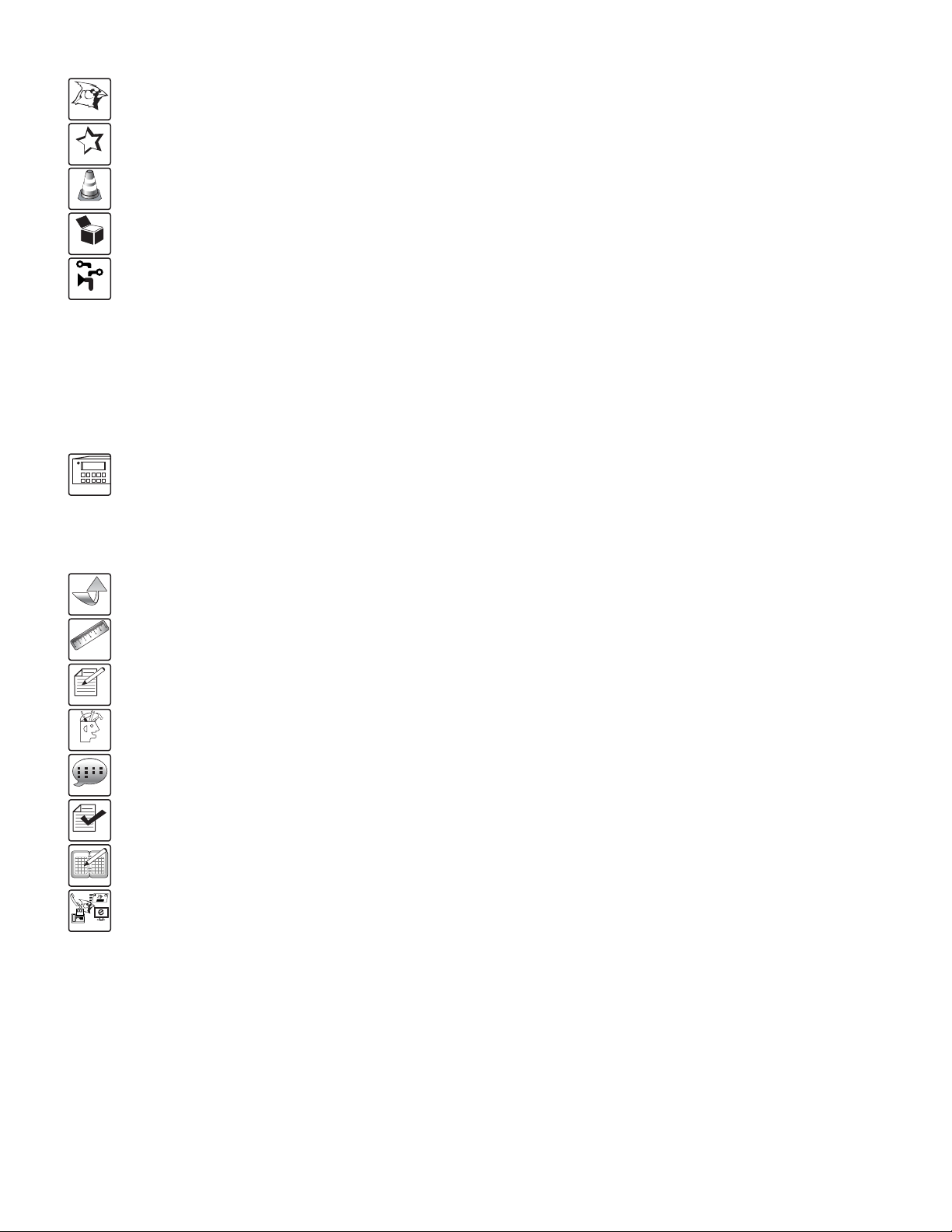
CONNECTOR INFORMATION
Either banana plug or insert type can be used to connect the
unit to speakers. Be sure to connect red (+) to red (+) and
black (–) to black (–). Otherwise, the sound output would be
180° out of phase and distorted.
Follow these steps if you are inserting the wire directly into
the speaker terminal.
1. Strip off the vinyl covering and twist the tip of the
wire core.
2. Loosen the knob and insert the wire core into the
terminal hole.
3. Tighten the knob to fix the wire core in place.
Do not allow the wire core to protrude or touch other
terminals or wires.
If the cores of differing wires touch, damage may result to
your components.
METHODS OF SPEAKER CONNECTION
1. Insert Type (Poor Connection)
2. Single Banana Plug Type (Better Connection)
SPEAKERS
SPEAKERS
NO GOOD
3. Double Banana Plug Type (Standard Connection)
SPEAKERS
3/4”
19 mm
1/4” to 1/4” Cable
1SHIELD
COLD
HOT
2
3
Balanced XLR Connectors
XLR TRS
Hot (+) Pin 2 Tip
Cold (
-
) Pin 3 Ring
Shield (Ground) Pin 1 Shield
XLR to RCA Cable
XLR to 1/4” Cable
GOOD

8
VIDEO
VIDEO
AUDIO
LD PLAYER
POWER
LD
DVD PLAYER
AUDIO
VIDEO
VIDEO
AUDIO
AUX PLAYER
POWER
AUX
VCD PLAYER
VCD
AUDIO
to the amplifier input. Then, connect the video source. Please
refer to the following diagram. To ensure high quality sound
and video, we recommend using high quality cables and
connectors.
CONNECTING THE AUDIO/VIDEO INPUT SOURCE
Before connecting the source (i.e. LD, DVD, VCD and AUX),
turn off the power for all machine, so it would protect electric
shock and prevent damage to the equipment. To connect the
AV source, the first thing to do is to connect the audio source
MA-350 is capable of driving four main speakers, which are
grouped in Group A and Group B. We recommend you
using different size of speakers for Group A (10-inch woofer
or bigger) and Group B (6-inch woofer). Under this
arrangement, Group A speaker can produce greater bass
music output while Group B speaker can produce clear
CONNECTING THE MAIN SPEAKER
RL
HD TV
MAIN RIGHT
SPEAKER
MAIN LEFT
SPEAKER
vocal. The mixing of music and vocal is important to produce
quality sound for singing. Therefore, the audience can feel
different effects from Group A and Group B speakers. You
can also adjust the vocal on both speakers, or you can adjust
the vocal in either speaker by adjusting the balance.
Applications
SYSTEM APPLICATIONS
MA-350 REAR VIEW
RL
SAFETY
MARK
USA 020898-1029536-28ITEMNO.D030906
360020112380
MODEL N O.: MA-350
CALIFOR NIA, UNIT ED STATES O F AMERICA
E-mail:[email protected]
www.NISSINDOUSA.com
ENGINEEREDAND DESIGN IN U.S.A.
SERIA L NO.
TO REDUCE THE RISK OF ELECTRIC SHOCK, DO NOT
REMOVECOVER. NO USER SERVICEABLE PARTS INSIDE
REFERSERVICING TO QUALIFIED SERVICE PERSONNEL.
CAUTION
RISKOF ELECTRIC SHOCK
DONOT OPEN
WITHOUTAUTHORIZATION
9
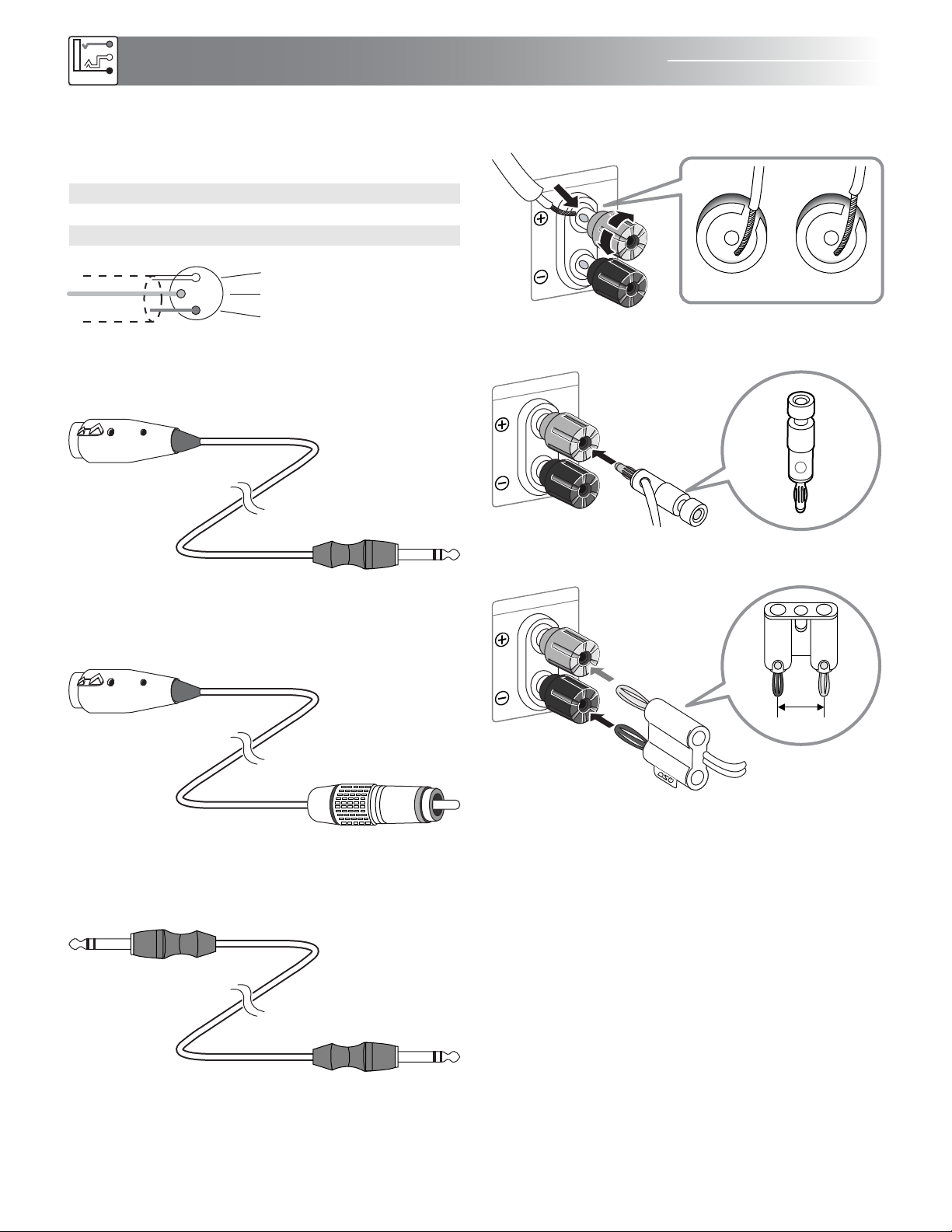
CONNECTING THE AUDIO OUTPUT SOURCE
CONNECTING THE VIDEO OUTPUT SOURCE
The MA-350 comes with two dedicated composite video
output. Typical connection usage such as for a small
classroom show in the diagram or it can be use similarly in
connecting to the amplifier with a KTV video touch screen
stand. If 3 or 4 more is needed, use an external composite
video distributor. If the wiring distance to the output source is
more than 25 feet. A composite video amplifier distributor is
needed; otherwise, the video will be very poor.
VIDEO PROJECTOR
RCA VIDEO OUT
OR
KTV VIDEO TOUCH
SCREEN STAND
RCA VIDEO OUT
INPUT
PIN1: SIG NAL GND
PIN2: SI GNAL +
PIN3: SI GNAL –
BRIDG E
PARAL LEL
STERE O
50HZ
25HZ
5HZ
OFF
ON
OFF
ON
CH-1 BR IDGE IN
CH-2 B RIDGE IN
SERIA L NO.:
CAUT ION
RISK OF ELE CTRIC S HOCK
DO NOT OPEN
BRIDG E
CH-1 OU TPUT
POWE R CABLE
FUSE
CH-2 O UTPUT
-
+
CH-1
+
-
+
-
CH-2
SAFETY
MARK
USA020898 -11
020898-11
ITEMNO. D0309 05
MODE L F FILTER C LIP LIMI TER GR OUND
REAR VIEW
INPUT
PIN1: SIGNAL GND
PIN2: SIGNAL +
PIN3: SIGNAL –
BRIDGE
PARALLEL
STEREO
50HZ
25HZ
5HZ
CH-1 BRIDGE IN
CH-2 BRIDGE IN
MODE LF FILTER
The Audio 1/4 unbalanced cable is a
standard audio signal connection. The XLR
balanced cable is a higher signal quality
connection which we strongly recommend
for best audio performance. However,
both types of connection CAN NOT be
connected at the same time.
AUDIO (XLR) BALANCE OUTPUT
XLR (MALE) TO RCA CABLE
RL
SAFETY
MARK
USA 020898-1029536-28ITEMNO. D030906
360020112380
MODEL NO.: MA-350
CALIFORNIA, UNITED STATES OFAMERICA
E-mail: support@nissindousa.com
www.NISSINDOUSA.com
ENGINEERED AND DESIGN INU.S.A.
SER IAL NO .
TO REDUCE THE RISK OF ELECTRIC SHOCK, DO NOT
REMOVE COVER. NO USER SERVICEABLEPARTS INSIDE
REFER SERVICING TO QUALIFIED SERVICE PERSONNEL.
CAUTION
RISK OF ELECTRIC SHOCK
DO NOT OPEN
WITHOUT AUTHORIZATION
MA-350 REAR VIEW
10
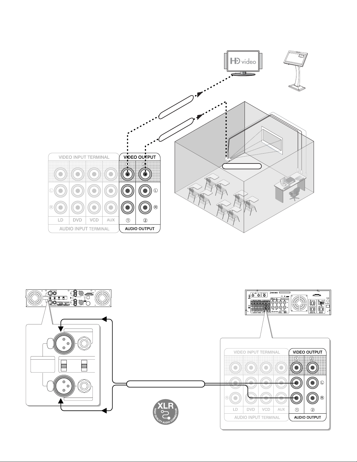
AUDIO OUT
The MA-350 is versatile. The differences for the MA-350
from the high-end models MA-940 is that it is less external
signal line outputs for recording and connection to external
power amplifiers to drive subwoofers and monitor speakers.
MA-350 is the basic model.
For example, if you are having a party, you may have guests
in the living room where the MA-350 and the 5 speakers are
located; at the same time, there are people in the backyard.
That’s when this feature comes in handy. By running
additional signal out lines to the back yard where another
power amplifiers can drive the subwoofer and monitor
speakers, or hook up the signal lines to the powered speak-
ers can then greatly expand the entertainment area. Please
note that we recommend using the wireless microphones in
the backyard for convenience.
BRIDGE
PARALL
STEREO
20X
40X
0.775V
LIFT
GND 110V 60Hz
AC POWER
INPUT
CH 1
BRIDGE
INPUT
CH 2
CH 1
CH 2
OUTPUT CH 2
CH 2
_
+
CH 1
_
+
OUTPUT CH 1
SENSITIVITY
GROUND
MODE
L
O
C
K
L
O
C
K
POWER AMPLIFIER
HOME KARAOKE ENTERTAINMENT
LIVING ROOM 500 sqft
REAR LEFT SPEAKER
MAIN LEFT SPEAKER
REAR RIGHT SPEAKER
MAIN RIGHT SPEAKER
If the distance from the living room to the backyard is more
than 25 feet, we recommend using an A/V distribution amplifier.
NOTE
BASS POWERED SUB
SUBWOOFER LINE OUT
LARGE ROOM ENTERTAINMENT 2000 sqft
CONNECTING THE AUDIO/VIDEO OUTPUT SOURCE

11
CONNECTING THE MICROPHONE INPUT
RL
SAFETY
MARK
USA 020898-1029536-28ITEM NO. D030906
360020112380
MODEL NO.: MA-350
CALIFORNIA, UNITED STATES OF AMERICA
E-mail: [email protected]
www.NISSINDOUSA.com
ENGINEERED AND DESIGN IN U.S.A.
SERIAL NO.
TO REDUCE THE RISK OF ELECTRIC SHOCK, DO NOT
REMOVE COVER. NO USER SERVICEABLE PARTS INSIDE
REFER SERVICING TO QUALIFIED SERVICE PERSONNEL.
CAUTION
RISK OF ELECTRIC SHOCK
DO NOT OPEN
WITHOUT AUTHORIZATION
#MPX VOCAL AID
VCD
INPUT SEL ECTION
AUX
LD DVD
4 #4
LD
3 #3
DVD
2
VOCAL
AID
#2
VCD
1
MPX
#1
AUX
16 BI T DI GI TAL KE Y CO NTROL LE R
P r o f e s s i o n a l K a r a o k e S y s t e m
KEY
MIC INPUT MIC T ONEMIC VOLUM E
MI C 1 MI C 2 MI C 3
MUSIC T O NE
TREBLEBAS SBAL A NCEBAS S T REB LE DEL AY
ECHO EFFEC T
REPEAT ECHO
POWER
OFF ON
MUSIC VOL UME
0 20
1 19
2 18
3 17
4 16
5 15
6
7
8
9 11
12
13
10
14
STEREO MIXING AMPLIFIER MODEL: MA-350
1 2 3
MIC M ASTER VO LUME
0 20
1 19
2 18
3 17
4 16
5 15
6
7
8
9 11
12
13
10
14
Adjust MIC Master Volume to 0 dB before inserting 1/4”
microphone plugs into the MIC inputs to avoid unpleasant
noise and protect your equipment from damage.
NOTE
WIRED MIC. 1 WIRED MIC. 2 GUITAR
connect to
MIC. receiver
(REAR MIC. 1)
connect to
MIC. receiver
(REAR MIC. 2)
This jack is for connecting microphones
to rear MIC. Input 1. They are at the
same terminal. Rear input is designed
for wireless microphone.
This jack is for connecting microphones
to rear MIC. Input 2. They are at the
same terminal. Rear input is designed
for wireless microphone.
12
MA-350
CONTROLS AND FUNCTIONS
REMOTE CONTROL:
Amplifier
2
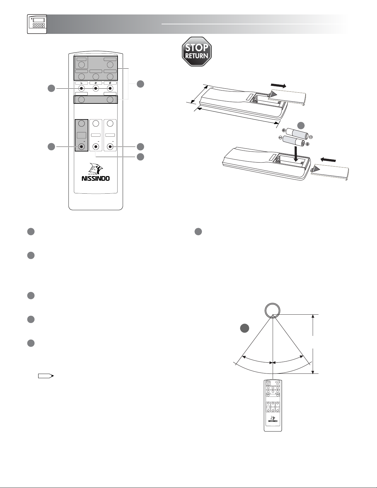
USING THE REMOTE CONTROL UNIT
When operating the remote control unit, point the unit's
infrared signal transmitter at the remote control remote
sensor on the front panel. The remote control unit can be
used within a range of about 18 feet (6m) from the
remote sensor, and within angles of up to about 30
degrees.
KEY CONTROL: LOW, NATURAL, HIGH
Key control button controls the music speed.
NON-WORKING FUNCTIONS
The highlight buttons (MUTE, AUTO, KOD, DVD, VOD ,
CENTER/SUB MONITOR, ECHO EFFECT) do not work
with this model.
MUSIC MASTER VOLUME CONTROL
Music Master Volume control from 00 to 90.
MICROPHONE VOLUME CONTROL
Microphone Master Volume control from 00 to 90.
INSERTING BATTERIES
Insert two size AA 1.5V (R6) alkaline batteries as shown.
Close the cover of the battery case.
Remove the batteries to avoid damage from possible battery
leakage whenever you anticipate that the remote control will
not be used for an extended period.
Handle the remote control with care. Avoid dropping it,
getting it wet, or placing it in direct sunlight, near a
heater, or where the humidity is high.
16
5
2 inches/50 mm
5.75 inches/150 mm
2
4
5
3
AA
ALKALINE
BATTERY
AA
ALKALINE
BATTERY
NOTE
IR
6
REMOTE CONTROL SENSOR
30o
30o
18 feet
(6 m)
CENTER/SUB
MONITOR
VOLUME▲VOLUME▼
DVDKOD
MUTE AUTO
VOD
VOL +
MUSIC
VOL
VOL +
MIC
VOL
VOL +
VOL
ECHO
EFFECT
1
23
4
NON-WORKING
FUNCTIONS
STOP RETURN MA-350 TO SELLERS
IMPORTANT: NON-WORKING REMOTE
This remote control is good for commercial KTV rooms
MA-350
CENTER/SUB
MONITOR
VOLUME▲VOLUME▼
DVDKOD
MUTE AUTO
VOD
VOL +
MUSIC
VOL
VOL +
MIC
VOL
VOL +
VOL
ECHO
EFFECT
NON-WORKING
FUNCTIONS

#MPX VOCAL AID
VCD
INPUT SEL ECTION
AUX
LD DVD
4 #4
LD
3 #3
DVD
2
VOCAL
AID
#2
VCD
1
MPX
#1
AUX
16 BI T DI GI TAL KE Y CONTROL LE R
P r o f e s s i o n a l K a r a o k e S y s t e m
KEY
MIC INPUT MIC TONEMI C VOLUM E
MI C 1 MI C 2 MIC 3
MUSIC T O NE
TREBLEBAS SBAL ANCEBAS S TREBLE DE L AY
ECHO EFFEC T
REPEAT ECHO
POWER
OFF ON
MUSIC VOL UME
0 20
1 19
2 18
3 17
4 16
5 15
6
7
8
9 11
12
13
10
14
STEREO MIXING AMPLIFIER MODEL: MA-350
1 2 3
MIC M ASTER VO LUME
0 20
1 19
2 18
3 17
4 16
5 15
6
7
8
9 11
12
13
10
14
13
1 6 832 7 94 5
12 13 14 15 1610 11
FRONT PANEL:
MIC 3 VOLUME CONTROL
This volume control microphone 3 volume level.
MIC TONE CONTROL: BASS
The bass controls the microphone low tones with 16
steps resolution, from -8dB ~ 8dB adjustment.
MIC TONE CONTROL: TREBLE
The treble controls the microphone high tones with 16
steps resolution, from -8dB ~ 8dB adjustment.
ECHO EFFECT CONTROL
These knobs control the music delay, repeat, and echo.
DELAY: This is the echo delay control for the microphone
effects. Turning the knob to increase and decrease the
echo delay time coming from the microphone; with 32
steps resolution, from 0 ~ 31 adjustment.
REPEAT: This is the echo repeat control for the
microphone effects. Turning the knob to increase and
decrease the repeat time coming from the microphone;
with 32 steps resolution, from 0 ~ 31 adjustment.
ECHO: This is the echo reverb control for the microphone
effects. Turning the knob to increase and decrease the
reverb time coming from the microphone; with 32 steps
resolution, from 0 ~ 31 adjustment.
MUSIC TONE CONTROL
for Music. These knobs control the music bass, middle,
and treble.
BASS: The bass controls the low tones with 16 steps
resolution, from -8dB ~ 8dB adjustment.
MID: The middle controls the mid-range tones with 16
steps resolution, from -8dB ~ 8dB adjustment.
TREBLE: The treble controls the high tones with 16 steps
resolution, from -8dB ~ 8dB adjustment.
POWER SWITCH ON/OFF
DISPLAY SCREEN
SOURCE INPUT TERMINAL: LD, VCD, CDG, AUX
MUSIC KEY CONTROL BUTTON
These buttons control the speeds of the music.
DIGITAL KEY CONTROL
MIC. GAIN VOLUME ADJUSTMENT
This microphones output level limiteris for limiting the
output power for speaker protection.
MIC MASTER VOLUME CONTROL
This volume control adjusts the different MIC volume settings.
MUSIC GAIN VOLUME ADJUSTMENT
This music output level limiter is for limiting the output
power for speaker protection.
MUSIC VOLUME CONTROL
This volume control adjusts the volume of the musical
source.
KEY CONTROL INPUT
MIC 1, 2 & 3 INPUT
MIC 1 VOLUME CONTROL
This volume control microphone 1 volume level.
MIC 2 VOLUME CONTROL
This volume control microphone 2 volume level.
14
15
17
18
1
2
3
8
9
4
5
6
7
10
11
12
13
1817
16
RL
SAFETY
MARK
USA 020898-1029536-28ITEM NO. D030906
360020112380
MODEL NO.: MA-350
CALIFORNIA, UNITED STATES OF AMERICA
E-mail: [email protected]
www.NISSINDOUSA.com
ENGINEERED AND DESIGN IN U.S.A.
SERIAL NO.
TO REDUCE THE RISK OF ELECTRIC SHOCK, DO NOT
REMOVE COVER. NO USER SERVICEABLE PARTS INSIDE
REFER SERVICING TO QUALIFIED SERVICE PERSONNEL.
CAUTION
RISK OF ELECTRIC SHOCK
DO NOT OPEN
WITHOUT AUTHORIZATION
14
17 20
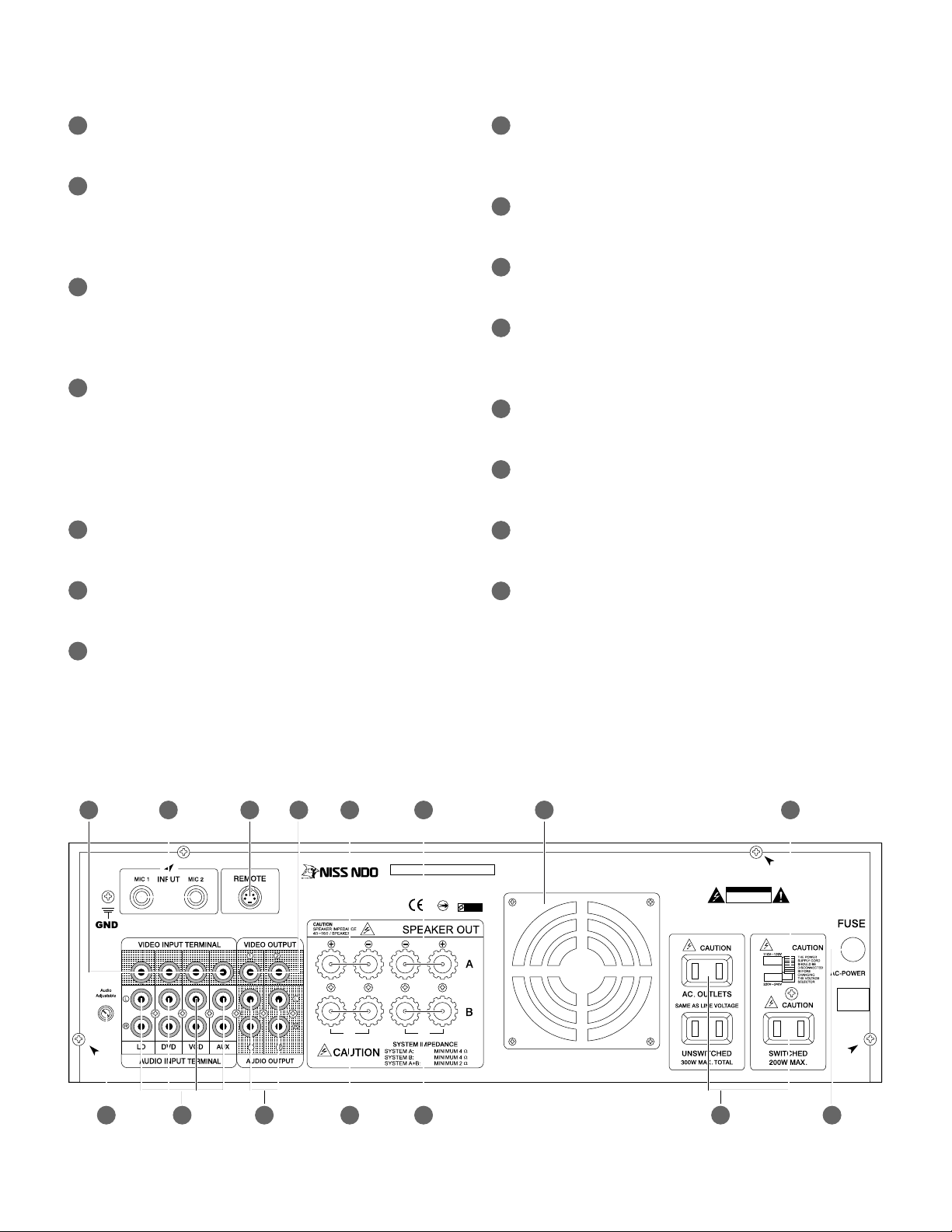
REAR PANEL:
POWER SUPPLY SWITCH
Use this switch to select the appropriate power outlet
supply voltage.
AUDIO INPUT LEVEL CONTROL
Adjust this control to balance the audio input level.
FOUR-SOURCE INPUTS FOR AUDIO
Four external audio input sources: LD, DVD, VCD, AUX.
AUDIO OUTPUT
Connet the input jacks of the extension power amplifier,
mixer, and video monitor to these RCA jacks.
MAIN LEFT SPEAKER POWERED OUTPUT: Dedicated
Group-B main left channel Powered Output.
MAIN RIGHT SPEAKER POWERED OUTPUT: Dedicated
Group-B main right channel Powered Output.
AC POWER OUTPUT SOCKET & AC POWER SUPPLY
SOCKET.
FUSE HOLDER: This is the housing for the power
supply fuse.
THREE-SOURCE INPUTS FOR VIDEO
Three external video input sources: KOD, DVD, VOD.
WIRELESS MIC REAR INPUTS (MIC4/MIC5)
This is the dedicated wireless microphone inputs
designed specifically to works with the available wireless
microphone reception base station.
REMOTE
This S Remote control terminal is specially design to
connect VOD control panel and/or the optional
programmable Effects Control Software Suite connector.
VIDEO OUTPUT
Dedicated composite video output. If 3 or 4 more is
needed, use an external composite video selector. If the
wiring distance to the output source is more than 25 feet.
A composite video distributor is needed; otherwise, the
video will be very poor.
MAIN LEFT SPEAKER POWERED OUTPUT
Dedicated Group-A main left channel Powered Output.
MAIN RIGHT SPEAKER POWERED OUTPUT
Dedicated Group-A main right channel Powered Output.
LOW NOISE DUAL UNITS COOLING FAN
24
19 23 2418 21
28 29
22
25 30 3126 27
17
18
19
20
21
22
23
25
26
27
28
29
30
31
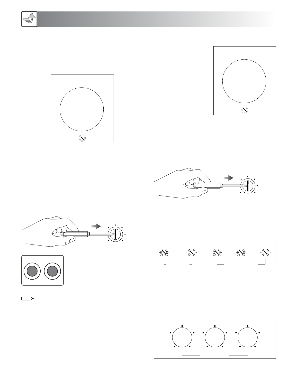
Operating
15
3. Music Volume Adjustment
Turn MUSIC VOLUME
clockwise to increase and
counter-clockwise to
decrease the music volume.
4. Music Gain Adjustment
Turn the pot to adjust the MUSIC GAIN. MUSIC GAIN is a
limiter for music volume. This feature is for limiting the output
power for speaker protection. Its function is to protect your
audio equipment from burning out caused by turning the
master music volume too high.
5. Microphone Tone Adjustment
The microphone tone for BASS, TREBLE, DELAY, REPEAT, and
ECHO can be adjusted individually by turning each pot.
6. Music Tone
Turn BALANCE to adjust the distribution of output level.
Turn BASS to adjust the bass output level.
Turn TREBLE to adjust the treble output level.
0 20
1 19
2 18
3 17
4 16
5 15
6
7
8
9 11 12
13
10
14
MUSIC VOLUME
DELAY
ECHO EFFECT
REPEAT ECHO
MIC TONE
BASS TREBLE
0 20
1 19
2 18
3 17
4 16
5 15
6
7
8
9 11 12
13
10
14
MIC MASTER VOLUME
MUSIC TONE
TREBLEBASSBAL ANCE
NOTE
MIC 1 MIC 2
REAR MIC. INPUT
OPERATING INSTRUCTIONS
MODE ADJUSTMENT
1. Microphone Master Volume Adjustment
Turn MIC MASTER VOLUME clockwise to increase and
counter-clockwise to decrease microphone master volume.
2. Microphone Gain Adjustment
Turn the pot to adjust the MICROPHONE GAIN.
MICROPHONE GAIN is a limiter for microphone volume.
This feature is for limiting the output power for speaker
protection. Its function is to protect your audio equipment
from burning out caused by turning the master microphone
volume too high.
In the front panel, there are three MICROPHONE INPUT jacks:
MIC 1, MIC 2, and MIC 3. In the rear panel, there are two
MICROPHONE INPUT jacks: MIC 1 and MIC 2.
Adjusting MIC 1 MIC VOL. will affect both the front and rear MIC
1 INPUTS at the same time.
Adjusting MIC 2 MIC VOL. will affect both the front and rear MIC
2 INPUTS at the same time.
Adjusting MIC 3 MIC VOL. will affect the MIC 3 INPUT.

DIMENSIONS (WxHxD) 17×5.5×15 in / 43.2×14×38 cm
PACKING DIMENSIONS
(WxHxD) 19.8×8.3×17.3 in / 50.2×21.1×43.9 cm
NET WEIGHT 23 Lbs / 10.4 Kg
SHIPPING WEIGHT 25.4 Lbs / 11.5 Kg
16
H. 5.5”
14 cm
D. 15” / 38 cm
INPUT SENSITIVITY/
IMPEDANCE 4.5mV / 3.5K ohm 300mV / 20k ohm
FREQUENCY
RESPONSE 40Hz~15kHz, +8/-3dB 20Hz~20kHz, +8/-3dB
TONE ELECTRICAL
CIRCUIT
BASS Control:100Hz+10dB
TREBLE Control:10kHz+10dB
BASS Control:100Hz±9dB
TREBLE Control:100Hz±9dB
POWER
REQUIREMENT
AC 110~120V or 220~240V,50Hz/60Hz
Power Consume: 142 Watts
VIDEO INPUT/OUTPUT 1Vp-p/75 ohm
POWER OUTPUT 120W+120W (6 ohm)
THD 0.05% (1kHz, 60W, 8 Ohm)
9 Steps, +2 -1/2 Tones
KEY CONTROL
RANGE
MIC PART MUSIC PART
PHYSICAL DIMENSIONS
Dimensions
OPTIONAL 19" RACK MOUNT KIT
The Rack Mount kit is optional. Please make sure to get the
right kit size, then put the amplifier into the rack. The rack is
used to protect the amplifier. With such portable equipment,
it is possible to have party at home anytime or use it for
Karaoke rental business.
The Bracket/Handler (optional) is used to hold your audio/video
equipment firmly in place, but not for transportation. If you need
to transport the equipment, we recommend you using the heavy
duty clamping rack shelf (optional) as illustrated in figure. You
should place the heavy duty clamping rack shelf into the
portable case. This would protect your equipment. There are
different sizes of the heavy duty clamping rack shelves to suit
your specific needs. Please note that the bracket/handler, rack
shelf and case are not included in the package. They are
optional items and sold separately.
Side View
SPECIFICATIONS
Spec
MOUNTING THE RACK
SHELF PANEL IN A RACK
HEAVY DUTY CLAMPING RACK SHELF
PORTABLE SYSTEM
0dB
Volume
CENTER
5-CHANNEL PO WER AMPLIFIER
POWER
OFF ON
0dB
Volume
Channel-A
Main Left
LIGHT
CUP
SIGNAL
POWER
0dB
Volume
Channel-B
Main Right
LIGHT
CUP
SIGNAL
POWER
0dB
Volume
Channel-C
Rear Left
LIGHT
CUP
SIGNAL
POWER
0dB
Volume
Channel-D
Rear Right
LIGHT
CUP
SIGNAL
POWER
MIC . VOLUM E
VOLMIC R O P H O N E TONE
MIC. INPUT
MIC1 MIC2
EXCITER
VOLHIGH SUBFREQ
Hz
MIC1 3 MIC 2 4 LOW REAR
TREBLE MID BASS
MOD E ADJUS T A B L E
CENTER
MUSICVOL
20 240
VOL
EXCITER MIC AUDIO SUB INPUT
SR
UP
DOWN
MEMORY
5C HANNEL AUDIO VIDEO EFFECTS PRO CESSOR
MUSIC VOL 10
CDG DVD VOD
POWER
Front View
POWER ANTENA-A CNANNEL-A DISPLAY CNANNEL-B DI SPLAY
CHANNEL-A
VOLUME ANTENA -B
CHANNEL-B
VOLUME
DUAL CHAN NEL VHF WIRE LESS SYSTE M
RF
AF
FREQ.
5 10 15 20 25 30 35 40
-30 -25 -20 -15 -10 -5 0 PEAK
000.000M
H
Z
MUTE
RF
AF
FREQ.
5 10 15 20 25 30 35 40
-30 -25 -20 -15 -10 -5 0 PEAK
000.000M
H
Z
MUTE
#MPX VOCAL A ID
VCD
INP UT SEL ECTIO N
AUXLD DV D
4 #4
LD
3 #3
DVD
2
VOCAL
AID
#2
VCD
1
MPX
#1
AUX
16 BIT DIG ITAL KE Y CONTRO LLER
Pr o f e s s i o n al K a r a o k e Sy s t e m
KEY
MIC I NPUT MIC T ONEMIC V OLUM E
MIC 1 MIC 2 MI C 3
MUS IC TON E
TREB LEBAS SBAL ANCEBAS S T REBL E DELAY
ECH O EFFE CT
REPE AT ECHO
POW ER
OFF O N
MUS IC VOL UME
0 20
1 19
2 18
3 17
4 16
5 15
6
7
8
9 11
12
13
10
14
ST EREO M IXI NG AM PLI FIER M ODE L: MA -35 0
1 2 3
MIC M ASTER V OLUM E
0 20
1 19
2 18
3 17
4 16
5 15
6
7
8
9 11
12
13
10
14
#MPX VOC AL AID
VCD
INPU T SELECT ION
AUXLD DVD
4 #4
LD
3 #3
DVD
2
VOCAL
AID
#2
VCD
1
MPX
#1
AUX
16B IT DIGI TAL KEY CO NTROL LER
Pr o f e s s i o n a l Kar a o k e Sys t e m
KEY
MIC INP UT MIC TO NEMIC VO LUME
MIC 1 MIC 2 MIC 3
MUSIC TONE
TREBL EBASSBALANCEBASS TREBL E DELAY
ECHO E FFECT
REPEA T ECHO
POWE R
OFF ON
MUSIC V OLUME
0 20
1 19
2 18
3 17
4 16
5 15
6
7
8
9 11
12
13
10
14
STE REO MIXI NG AMPLI FIER MO DEL: MA- 350
1 2 3
MIC MA STER VOL UME
0 20
1 19
2 18
3 17
4 16
5 15
6
7
8
9 11
12
13
10
14
17”
43.2 cm
5.5”
14 cm
15”
38 cm
Troubleshooting
17
TROUBLESHOOTING
1. MUSIC VOLUME IS TOO LOW
Symptom: the music volume is too low.
Probable cause: the music volume limiter is set too low.
Remedy: adjust to a higher “Max Music Volume.”
3. MIC MASTER VOLUME IS TOO LOW
Symptom: the mic master volume is too low.
Probable cause: the mic master volume limiter is set too low.
Remedy: adjust to a higher “Max Mic Master Volume.”
4. NO SOUND FROM MICROPHONE
Probable cause: the microphone cable is not connected, and
microphone volume or mircophone is not trun on.
Remedy:
• Make sure the microphone cable is connected properly.
• Check to see if the microphone and/or the receiver are
turned on.
• Check the microphone volume.
5. NO POWER
Symptom: the machine has no power.
Remedy: check to see if the power cable is well connected
and that the power switch on the front panel is turned on.
6. BAD AUDIO OR MICROPHONE SOUNDS
Remedy:
• Check the source of your audio (CD, DVD) to
see if it’s scratched.
• Check your audio cables or microphone cables.
• Use a better audio cable or 3pin XLR mic cable.
7. NO PICTURE
Remedy:
• Check to see if video sources are selected accordingly.
• Check to see if the video cables are plugged in correctly.
8. VIDEO PROBLEM
Symptoms: the video display appears in black and white
color only or it has unstable image.
Possible Causes:
1. Video source (i.e. DVD player) is in different formats like
NTSC or PAL. Therefore, you should select the right “Video
Format” in the “Output” of the DVD player. It is because the
video display is incompatible with the video source.
2. The video out from the amplifier to the video display has
a distance over 25 feet. Therefore, you need to add an
additional signal distribution amplifier to further enhance the
signals for longer destinations.
3. You may be using the wrong cable for connection. The
cable for video signal is different from the cable for audio,
microphone and speaker. Therefore, you should use coaxial
cable for connection.
4. You may be using a low quality cable with poor connec-
tion. We highly recommend you using high quality
audio/video cable for connection.
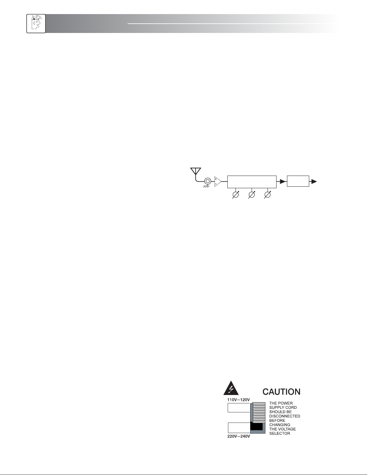
9. AMPLIFIER SHUT DOWN/INTERFERENCE NOISE
Symptom: the amplifier turned on but there is no music
coming out from the speaker powered output channels.
Probable cause: this unit comes with multiple switch able
AC-power. For North America its 115V and for Asia and
Europe markets are 230V.
Remedy: make sure that the AC-power supply is connected
to the correct voltage level according to the local market.
See illustration below for the proper switching of the
AC-power supply level.
LOW MID HIGH
Video Signal Amplifier
KD-SCDA8
VIDEO BLOCK DIAGRAM
Video
Decoder Video Out

18
FINAL WORDS TO USER
The engineering team of Nissindo has many years of
experience in audio equipment design. The team constantly
develops new audio technologies, designs innovative audio
and Karaoke equipment to suit your specific needs and
provides you great ideas for home entertainment.
Our engineering team also designs audio equipment for
commercial use by restaurants, coffee shops, churches, and
school auditoriums, etc. If the commercial area for audio
equipment installation exceeds 2,000 square feet, we highly
recommend you to hire audio professionals to handle the
installation in order to avoid risks in breaking the equipment
with improper installation and safety protection purposes.
We also provide educational and technical information on
audio equipment and technologies. For example, we provide
free installation diagrams to make it easier to connect the
system. In addition, to get best connections for the sharpest
image and sound quality, we provide hot tip for choosing
the high quality type of A/V cable connections. Free
information on audio equipment and technologies available
for download from our website,
www.NissindoUSA.com.
Please do not remove the “Yellow
Label” in the rear of the machine;
otherwise, the warranty will be void
automatically. We design it to protect
your own safety. If repair and
maintenance service is needed,
please contact us directly or hire a
professional technician. To learn more
about the technical aspects, visit our
website www.NissindoUSA.com and download the
relevant information for review.
Before hooking up the system, turn off the AC powers on all
machines including audio/video equipment and TV.
Otherwise, it may damage the equipment, especially on the
HDTV in which a spot might appeared on the TV screen.
After hooking up the system, double check the audio/video
connections to ensure that they are connected correctly.
Sometimes, loose or poor cable quality would affect
the microphone effects, picture quality, or even cause the
machine to shut down suddenly.
Again, we must thank you for choosing Nissindo product.
We hope you can make the best use of the machine and
enjoy it for years to come. If you have any questions
regarding our product, please feel free to contact us at
www.NissindoUSA.com.
Any form of
tampering with this
product, will void
the warranty.
NOTE
Final Words
10. PROTECTION FOR AUDIO/VIDEO EQUIPMENT
Before you hook up or disconnect any audio/video equip-
ment, you must turn off the power for all equipments. Other-
wise, it may cause black spots to appear on the LCD or
Plasma TV screen.
11. NOISE AND DISTORTION
When humming noise or displeasing sound appears, you
can replace the supplied power cord with an AC power
cord with a magnetic device as shown in the figure below.
In North America many families own satellite TVs, HD TVs
and cable TV receivers. They may cause interference which
affect both audio and video equipment. The power cord as
shown in figure 2 may help eliminate the humming sound
and enhance TV picture quality.
12. SOUND PROBLEM: No sound.
REMEDY:
Positive and negative of
speaker wire are touching
each other at the terminals.
We recommend using
double banana plugs.
3 prong to 2 prong adaptor
110V~120V
FIGURE 1
Quality Power Cord:
105°C 3C/18AWG 300V
FIGURE 2
NOTE
SPEAKERS

19
WARRANTY
ONE-YEAR LIMITED WARRANTY FOR HOME USE
EQUIPMENT
Our one-year warranty covers both parts and labors. The
warranty becomes effective from the date of your purchase for
one year.
Our warranty only covers defects due to product
defectiveness with free of defects in materials or workmanship.
However, our warranty does not cover defects due to normal
wears, damage in transit, improper use, abuse or failure to
follow the proper instructions for maintenance. This warranty is
void in the event of unauthorized repairs, alternations,
modifications and removing of the product label.
Please also note that our warranty does not cover any
shipping cost for the return of defective products to us for
inspection, repair and maintenance. Our warranty for
Nissindo products can only be executed in North America.
90-DAY LIMITED WARRANTY FOR PUBLIC AND
COMMERCIAL USE EQUIPMENT
Our 90-day warranty applies to speakers, amplifiers, mixers
and microphones for both public and commercial use such as
restaurant, coffee shop, KTV nightclub, church and school, etc.
It covers both parts and labors. The warranty becomes
effective from the date of your purchase for 90 days.
Our warranty only covers defects due to product
defectiveness with free of defects in materials or workmanship.
However, our warranty does not cover defects due to normal
wears, damage in transit, improper use, abuse or failure to
follow the proper instructions for maintenance. This warranty is
void in the event of unauthorized repairs, alternations,
modifications and removing of the product label.
Please also note that our warranty does not cover any
shipping cost for the return of defective products to us for
inspection, repair and maintenance. Our warranty for
Nissindo products can only be executed in North America.
Warranty
ADDITIONAL NOTES:
1. Limited warranty for home use equipment is only valid in
North America.
2. Limited warranty is valid only if you purchase our products
from our authorized dealers (including both regular retailers
and online retailers) in North America. If you choose to
purchase our products from an authorized dealer, we will not
provide any limited product warranty for you. To protect your
limited product warranty, please purchase our products from
one of our authorized dealers in North America near you.
3. Limited warranty is automatically void if the yellow label
stating “No Warranty After Opening” is removed from the
product.
TO REGISTER YOUR WARRANTY
Please fill out the warranty card that came with your unit,
download or submit online warranty form. However, we
need the invoice for your purchase in order to process this
warranty. You may also register your warranty online.
Please visit our website at www.NissindoUSA.com.

20
AGENCY REGULATORY NOTICES
Federal Communications Commission Notice
These limits are designed to provide reasonable protection
against harmful interference in a residential installation. This
equipment generates, uses, and can radiate radio frequency
energy and, if not installed and used in accordance with the
instructions, may cause harmful interference to radio
communications. However, there is no guarantee that
interference will not occur in a particular installation. If this
equipment does cause harmful interference to radio or
television reception, which can be determined by turning the
equipment off and on, the user is encouraged to try to correct
the interference by one or more of the following measures:
• Reorient or relocate the receiving antenna.
• Increase the separation between the equipment and the
receiver.
• Connect the equipment into an outlet on a circuit different
from that to which the receiver is connected.
• Consult the dealer or an experienced radio or television
technician for help.
Modifications
The FCC requires the user to be notified that any changes or
modifications made to this device that are not approved may
void the user’s authority to operate the equipment.
Cables
Connections to this device must be made with shielded cables
with metallic RFI/EMI connector hoods to maintain
compliance with FCC rules and regulations.
Materials Disposal
Disposal of this material can be regulated because of
environmental considerations. For disposal or recycling
information, contact your local authorities or the Electronic
Industries Alliance (EIA) (http://www.eiae.org).
Disposal Of Waste Equipment By Users In
Private Households In The European Union
This symbol on the product or on its packaging indicates that
this product must not be disposed of with your other
household waste. Instead, it is your responsibility to dispose of
your waste equipment by handing it over to a designated
collection point for the recycling of waste electrical and
electronic equipment. The separate collection and recycling of
your waste equipment at the time of disposal will help to
conserve natural resources and ensure that it is recycled in a
manner that protects human health and the environment. For
more information about where you can drop off your waste
equipment for recycling, please contact your local city office,
your household waste disposal service or the shop where you
purchased the product.
Japanese Notice
Japanese Power Cord Notice
Japanese Material Content Declaration
A Japanese regulatory requirement, defined by Specification
JIS-C-0950, 2005, mandates that manufacturers provide
Material Content Declarations for certain categories of
electronic products offered for sale after July 1, 2006.
Korean Notice
Recycling Program
The terms and availability of these programs vary by
geography because of differences in regulatory requirements
and local customer demand.
因为在当地的监管要求和客户的需求,这些条件和程序的情
况不同。
Notices
Other manuals for MA350
1
Table of contents
Other Nissindo Karaoke System manuals


