Nitek PVR164 User manual

PVR164
16 Port Video, Power and Data Receiver
NITEK®
De Schans 19-21 2a
8231 KA Lelystad
Tel: +31(0)320-2300005
Fax: +31(0)320-282186
WWW.NITEK.NL
USA
5410 Newport Drive, # 24
Rolling Meadows, IL 60008
Phone: (847) 259-8900
Fax: (847) 259-1300
WWW.NITEK.NET
EUROPE
Rev: 051810
Reduce risk of fire or electrical shock. Do not
expose this product to rain or moisture.
Installation and
Operation Manual
19.0
19.0
5.0
5.0
1.710
1.710
123 4
DATA
DATA
DATADATA
123412341234
PVR164 UTP VIDEO HUB
NITEK
UTP Video System
ABC D
12
34
DATA IN
DATA IN
DCBA
+
-
DATA IN
DATA IN
DATA IN
DATA IN
DATA IN
DATA IN
+
-
+
-
+
-
12
34
12
34
12
34
13
+
-
+
-
+
-
+
-
24
13
+
-
+
-
+
-
+
-
24 13
+
-
+
-
+
-
+
-
24
13
+
-
+
-
+
-
+
-
24
Specifications
Camera Port RJ45 Connector
Data Port Push in Connector
Video Port BNC Connector
Power Screw terminals for
16 to 24 AWG wire
Power Requirements Class 2 SELV
Temperature Range -20°C to +65°C
Humidity Range 0 to 98%, non-condensing
INSTALLATION
Rear Panel Connections
1) BNC jacks are video out ports. Connect to DVR unit or other video display. A green LED will light
on the RJ45 port to indicate the presence of video.
2) Control data is connected to the push-in terminals marked “DATA IN”. An amber LED on the front
panel will light or flash to indicate data is passing through the ports.
3) Power for each camera port is marked “+” and “-” for DC power. AC power can be connected to
either terminal. A red LED will indicate power is present on the RJ45 port.
Front Panel Connections
1) There is one RJ45 port per camera. This port combines all of the signals needed for the CCTV
camera into one cable, which should be wired using the 568B standard on both ends.
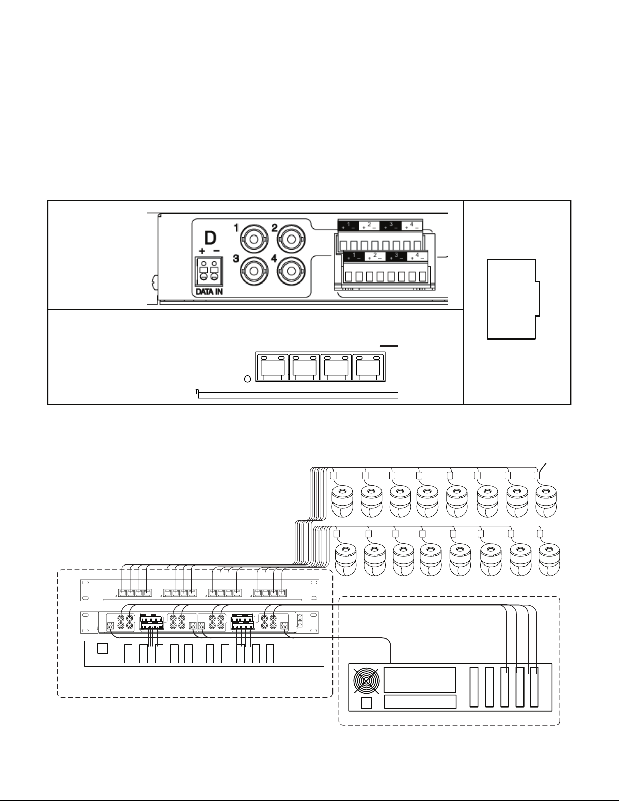
Standard System Hookup
VB43ATF
Rackmount 16 port Class 2 SELV Power Supply
DVR
Cables
4-pair Category Cables
Wiring / IDF Telecom Closet
Control Room / MDF
Video
Data
Front
View
Back
View
Video, Power, and Data
123 4
DATA
DATA
DATADATA
123412341234
PVR164 UTP VIDEO HUB
NITEK UTP Video System
ABC D
12
34
DATA IN
DATA IN
DCBA
+
-
DATA IN
DATA IN
DATA IN
DATA IN
DATA IN
DATA IN
+
-
+
-
+
-
12
34
12
34
12
34
13
+
-
+
-
+
-
+
-
24
13
+
-
+
-
+
-
+
-
24 13
+
-
+
-
+
-
+
-
24
13
+
-
+
-
+
-
+
-
24
Front Panel
Connections
Back Panel
Connections 8 + Power
7 - Power
6 + Power
5 + Data
4 - Data
3 - Power
2 - Video
1 + Video
568B
123 4
DATA
NITEK
UTP Video System
A
12
34
DATA IN
DCBA
+
-
DATA IN DATA IN DATA IN
+
-
+
-
+
-
12
34
12
34
12
34
Table of contents
Other Nitek Receiver manuals


