Nitto MYTON MLG-25 User manual

Due to continuous product development/improvement the specifications and
configurations in this document are subject to change without prior notice.
Manufactured by :
NITTO KOHKI Co., Ltd.
2-9-4, Nakaikegami, Ohta-ku,
Tokyo, 146-8555, Japan
TEL : (81)-3-3755-1111
FAX : (81)-3-3753-8791
URL : www.nitto-kohki.co.jp
Specifications
Model MLG-25 MLG-40 MLG-50 MLG-70
Maximum Operating Pressure MPa 0.6
Air Consumption (No Load) m3/min 0.42 0.45 0.7 0.7
Maximum Power W 210 710 1,100 1,100
Rated Speed (No Load) r/min(min-1) 19,000 13,000 11,000 7,600
Depressed Center
Grinding Wheel
Diameter mm(inch) 58 (2-9/32) 100 (4) 125 (5) 180 (7)
Hole mm(inch) 9.6 (3/8) 16 (5/8) 22 (7/8) 22 (7/8)
Mass (Weight) kg 0.6 1.4 2.5 2.5
Sound Pressure Level dB(A) 90 88 89 89
Sound Power Level dB(A) 95 99 100 100
Vibration Level
[Uncertainty K]
Body m/s2[m/s2]≦2.5
(1.8 [0.83]) 6.3 [1.10] 3.6 [0.85] 3.8 [0.87]
Handle m/s2[m/s2]−−
4.1 [0.90] 6.2 [1.10]
Thread Size of Air Inlet Rc1/4 Rc3/8 Rc3/8 Rc3/8
PNEUMATIC ANGLE GRINDER
Please read this manual carefully before you attempt to use
your tool so that you may use it properly and safely.
MYTON
Model MLG-25, MLG-40, MLG-50, MLG-70
PROFESSIONAL TOOL
Keep the manual handy – so you can use it whenever necessary.
Original Instructions
MLG-25
MLG-50 MLG-70
MLG-40

1
The following Safety notations are used throughout the manual to highlight safety precautions for the user and for
the tool.
WARNING: Indicates a potentially hazardous situation which, if not avoided by following the
instructions given, could result in death or serious injury.
CAUTION: Indicates a potentially hazardous situation which, if not avoided by following the
instructions given, could result in injury or material damage.
Please note, however, that failure to observe safety precautions under the “ Caution” category could result in a
serious occurrence depending on the situation: please observe all safety precautions in the manual.
Caution: Important precautions for tool setup, operation and maintenance.
Thank you very much for your purchase of this
Nitto Kohki product.
Before using your tool, please read this manual
carefully so that you may use it properly to get
the most out of it.
Please keep the manual handy - so you can
use it whenever necessary.
・English : Please ask your dealer or
distributor for instruction manual
in local language(s).
・German : Bitte fragen Sie lhren Händler
nach eine Betriebsanleitung in
Landessprache.
・French : S'il vous plait, veuillez demandez
á votre foumisseur de manuel
instruction en langue locale.
・Spanish : Por favor, cantacte con su
distribuidor para el manual de
instrucciones en español.
・Portuguese : Por favor pessa ao seo agente
ou distribuidor o manual de
instrucces ih linguagen local.
・Italian : Per Manuale Istruzioni in lingua
locale Vi preghiamo di rivolgervi
al rivenditore o distributore.
・Dutch : Vraag uw handelaar
om een nederladstalige
gebruiksaanwijzing.
・Swedish : Be er lokala Åtreförsäljare eller
distributör om manualer pá
svenska.
・Danish : Venligst henvend Dem til den
danske distributør for instructions
manualer.
・Polish : Prosze pytac swojego dealera
lub dystrybutora o instrukcje
obslugi w jezyku localnym.
・中文 :請向當地供應商或経銷商詢問中
文使用説明書
CONTENTS page
IMPORTANT SAFETY INSTRUCTIONS ……………………2
GENERAL: TOOLS ……………………………………………2
GENERAL: PNEUMATIC TOOLS …………………………3
INSTRUCTIONS FOR THIS TOOL …………………………4
1. USAGE ……………………………………………………5
2. CHECK THE CONTENTS OF THE PACKAGE ……… 5
3. NAME OF PARTS ………………………………………5
4. AIR SUPPLY ………………………………………………6
5. PREPARATION (MLG-50, MLG-70) ……………………6
6. GRINDING WHEELS ……………………………………6
7. MOUNTING AND REMOVING GRINDING WHEEL …7
8. HOW TO OPERATE THE TOOL ………………………8
9. STORAGE ………………………………………………… 9
10. MAINTENANCE ………………………………………… 9
11. ORDERING SERVICE PARTS ……………………… 10
12. EXPLODED DIAGRAM : MLG-25 …………………… 11
13. EXPLODED DIAGRAM : MLG-40 …………………… 12
14. EXPLODED DIAGRAM : MLG-50 …………………… 13
15. EXPLODED DIAGRAM : MLG-70 …………………… 14
PICTOGRAM
Warning: It might be dangerous to operate the tool if
the instructions supplied are not followed.
Using this tool improperly could result in serious injury.
Read the instruction manual before using.
Always wear suitable eye protection.
Always wear suitable hearing protection.
Always wear respiratory protective equipment (PPE).

2
IMPORTANT SAFETY
INSTRUCTIONS
When using the tool, please observe the safety
precautions below to prevent possible accident or
injury.
GENERAL: TOOLS
WARNING
TO OPERATORS
●Wear proper clothing for the type of work being
done.
Take care to avoid entanglement with the moving
parts of the tool with clothing, ties, hair etc. If items
become entangled it will cause the operator to be
pulled towards the tool and lead to possible cause of
accident or injury.
●Always wear suitable eye protection.
Remember, regular glasses are not safety glasses.
The lenses are only shock resistant, which will not
give you sufficient eye protection you may need in
your working environment.
●Always wear suitable hearing protection.
●Wear respiratory protective equipment (PPE).
Wear respiratory protective equipment (PPE) when
working in an environment where dust particles are
generated in operation.
●Avoid working posture that is too stressful.
Always ensure a firm footing and well balanced
posture.
●Do not operate the tool if you are too tired.
●Never touch any moving parts of the tool when
running.
ABOUT WORK AREA
●Keep the work area clean.
Cluttered work areas (e.g. workbench) invite
accidents.
●Carefully select the work area.
Do not expose tool to rain.
Do not use tool in a wet or soaked area.
See that the work area is adequately illuminated.
●Never work near inflammable liquid or in a
potentially explosive atmosphere.
●Keep children away from the work area.
Keep children and unauthorized people away from
the work area to avoid accident or injury.
●Some tools generate high noise levels.
Check to be sure that the use of this tool conforms
to all local noise regulations.
BEFORE OPERATION
●Inspect tool before use.
Before using, check that screws are securely
tightened, that any protective cover or guard is
securely in place, other parts are free from damage
and that the tool runs as it should.
Check that moving parts are properly adjusted for
positioning and tightened, that parts are free from
damage and properly mounted, and that all other
parts are in good condition for normal operation.
Should you find any damage to the protective
cover or other part, replace it in accordance with
the Operation Manual. If there are no instructions
in the Manual, please contact the sales agent
through which you have purchased your tool or an
authorized dealer near you for repair.
Likewise, if a switch failure occurs, contact sales
agent through which you have purchased your tool
or an authorized dealer near you for repair.
Do not use the tool if it does not start or stop with
the start/stop switch.
●Securely mount cutter
An improperly mounted cutter may fly out, causing
possible damage to the tool or injury to the operator.
●Always remove spanner, wrench, etc., once
adjustment has been made with them.
●Use a tool appropriate for the application.
Avoid heavy-duty application that is beyond the
capacity of tool.
●Do not use the tool for purposes other than what
it is designed for.
●Do not abuse tool.
Use tool in accordance with the specifications: you’ll
get the most out of it while ensuring safety.
●Securely fasten workpiece in place.
Use a vice or clamp to securely fasten the workpiece
in place. It is much safer this way than holding it in
your hand, allowing you to operate the tool with both
hands.
ABOUT HANDLING
●How to store tool.
When the tool is not used, store it in a dry area and
out of reach of children.
●How to carry tool.
Do not touch the start switch while the tool is being
carried.
●Do not leave the tool unattended while it is
running.
Turn off the start switch and disconnect the tool from
power source. Do not leave the work area until the

3
tool comes to a complete stop.
MAINTENANCE/SERVICE
●Do not take apart or modify tool.
Disassembly or modification carried out without
the supervision of a qualified or authorized service
engineer could result in an accident or injury.
●Inspect cutting tool and accessories, etc.
Always check to see that cutting tool and
accessories, etc. are in good operating condition
without damage or deterioration before you mount
them on the tool. Should you find any damage to
an accessory or part, please contact sales agent
through which you have purchased your tool or an
authorized dealer near you for repair.
●Check parts for damage.
When you have found damage to accessory or other
part, carefully check the damaged part to determine
the extent of influence it has upon the functions
of the tool – that is, determine whether it can still
perform its normal functions.
Check to see that the linkage of the moving parts
is OK, that all parts are OK without damage,
that they are properly mounted, and that the tool
functions normally. Should you find any damage
to an accessory or part that may hamper proper
functioning of the tool, please contact sales agent
through which you have purchased your tool or an
authorized dealer near you for repair.
●Have your tool repaired at an authorized Nitto
Service Center.
For repair or parts replacement, please contact the
sales agent through which you have purchased your
tool or an authorized dealer near you.
●Use only Nitto genuine parts.
Use of improper parts may result in serious
occurrence.
To obtain a Nitto genuine part, consult this Manual
or contact the sales agent from which you have
purchased your tool directly.
●Do not detach label or nameplate from tool.
When a label/nameplate gets damaged, worn or
becomes missing, contact the sales agent through
which you have purchased your tool or Nitto Kohki
Co. Ltd, directly for a replacement.
DISPOSAL
●When a tool is taken permanently out of service, it
is advised that the tool is disassembled, degreased
and parts separated by material and recycled locally
in the appropriate manner.
GENERAL: PNEUMATIC
TOOLS
WARNING
●Use appropriate air pressure.
Excessively high air pressure will increase the
number of revolutions or strokes causing not only
potential premature failure/breakage but could also
lead to an unexpected accident or injury.
●Connect tool to air supply line.
There are various types of pipes running in a factory
in addition to the pneumatic line (such as oxygen,
nitrogen, gas and water). For this reason, always
ensure that you are connecting to the pneumatic
line.
●Start tool properly.
Turn the start switch OFF before connecting to the
air supply line.
●Always disconnect the tool from the air supply
line before putting on/taking off any accessory
and prior to carrying out any maintenance work.
●Avoid exposure to exhaust air.
Pneumatic tool exhaust air contains oil and
contaminated moisture. Make sure the exhaust air is
not directed towards your face or anyone else within
the work area.
●Keep tool off electricity.
This pneumatic tool is not electrically insulated. To
avoid a potential electric shock do not use where
there is a possibility of coming into contact with live
electricity.
CAUTION
●Handle tool carefully.
Abusive use of tool could invite failure or accident.
Do not throw, drop or shock the tool.
●Handle connecting hose carefully.
Do not carry the tool by the air hose.
Do not pull the air hose to disconnect.

4
INSTRUCTIONS
FOR
THIS TOOL
About Your Tool
WARNING
●Protect your body from the chips/filings.
Hot chips/filings may fly out from the work piece.
Always wear safety glasses, dust mask, earplugs,
gloves (except knitted gloves) and long-sleeved
garment.
Keep your face well away from the work piece.
●Always use a Grinding Wheel with a maximum
operating speed (m/s) rating equal to or exceeding
the labeled speed of the tool. Make sure the
dimensions of the Grinding Wheel you are using
is applicable to the specification of the grinder.
●Make sure there are no cracks, chips or damage
to the Grinding Wheel prior to use. Do not use
any wheels wet or without labels.
●Use Nitto Kohki’s Wheel Flanges only. However,
do not use any of them which have cracks, chips
or worn. Do not use the alternative flanges or flat
washers.
●Make sure if the Grinding Wheel is adaptable to
the Wheel Flanges.
Do not use reducing bushing to meet the Wheel
Lock unless they are supplied by the Grinding Wheel
manufacturer.
●Make sure there are no cracks, distortion or wear
marks on the thread of the Spindle or Wheel
Lock.
The label on the wheel has to be the same or bigger
diameter than that of a Spindle.
●Make sure if there is any cracks, distortion or
worn on a thread of a Spindle or Wheel Lock.
Do not use the grinder if you ever find one.
●Do not use the side of the Grinding Wheel (except
for specific side use Grinding Wheels)
●Always use the Wheel Guard for the grinder if
the maximum diameter of the Grinding Wheel is
over 50mm.
●Use the Wheel Guard provided.
Failure to do so could result in injury.
●Replace damaged, bent or severely worn Wheel
Guard. Do not use any Wheel Guard which can
damage the Grinding Wheel.
●Air pressure for the grinder must not exceed
0.6MPa (6kgf/cm2).
●Do not start or stop grinders suddenly.
Open a Throttle Lever gradually when you start
operation.
●After a grinder has been repaired and returned,
check the no load speed with a tachometer
before you use to make sure its actual speed
at 0.6MPa (6kgf/cm2) does not exceed the rated
speed printed on the Wheel Guard. Do the same
check after each stage of the work process of
work even in normal use. Set the Adjust Valve to
the maximum speed position when you check
the no load speed.
●Only qualified/trained operators should attach
or replace Grinding Wheels as well as checking/
testing them.
●Release the Throttle Lever when air supply is
stopped.
●Make sure no one is around grinding
circumferences before trial running.
●Run a trial for a minute before start grinding and
for three minutes after replacement of Grinding
Wheels to make sure there is no problem on the
grinder.
●Grind slowly until the Grinding Wheels get
warmer in case Wheels seem cold at the start.
●Always operate the grinder at the correct angle.
(15° 30°) . (Fig.1)
Grinding Surface
15°〜30°
Fig. 1
●Do not put any inflammable liquid or use
the grinding tool in a potentially explosive
atmosphere as there is a possibility of sparks
when grinding which could cause a fire/
explosion.
5
1. USAGE
This tool is for grinding workpieces using a Type 27
Depressed Center Grinding Wheel.
2. CHECK THE CONTENTS OF THE PACKAGE
Check the contents and make sure that the tool does
not have any damage which may have occurred
during transportation. The contents should correspond
to the list as follows. In case of damage/missing
parts, please contact the sales agent from whom you
purchased the tool.
MLG-25
Package Contents Qty Check
MYTON MLG-25 1set
Grinding Wheel GS #80 1
Hex. Socket Screw Key 5 1
Single Ended Spanner 19 1
Bushing R1/4×NPT1/4 1
Instruction Manual 1
Declaration of Conformity 1
Caution for Use 1
MLG-40
Package Contents Qty Check
MYTON MLG-40 1set
Hex. Socket Screw Key 6 1
Bushing R3/8×NPT3/8 1
Instruction Manual 1
Declaration of Conformity 1
Caution for Use 1
MLG-50
Package Contents Qty Check
MYTON MLG-50 1set
Handle Ass’y 1set
Wheel Guard Ass’y 1set
Hex. Socket Screw Key 6 1
Hex. Socket Screw Key 4 1
Pin Face Wrench 1
Bushing R3/8×NPT3/8 1
Instruction Manual 1
Declaration of Conformity 1
Caution for Use 1
MLG-70
Package Contents Qty Check
MYTON MLG-70 1set
Handle Ass’y 1set
Wheel Guard Ass’y 1set
Hex. Socket Screw Key 6 1
Hex. Socket Screw Key 10 1
Bushing R3/8×NPT3/8 1
Instruction Manual 1
Declaration of Conformity 1
Caution for Use 1
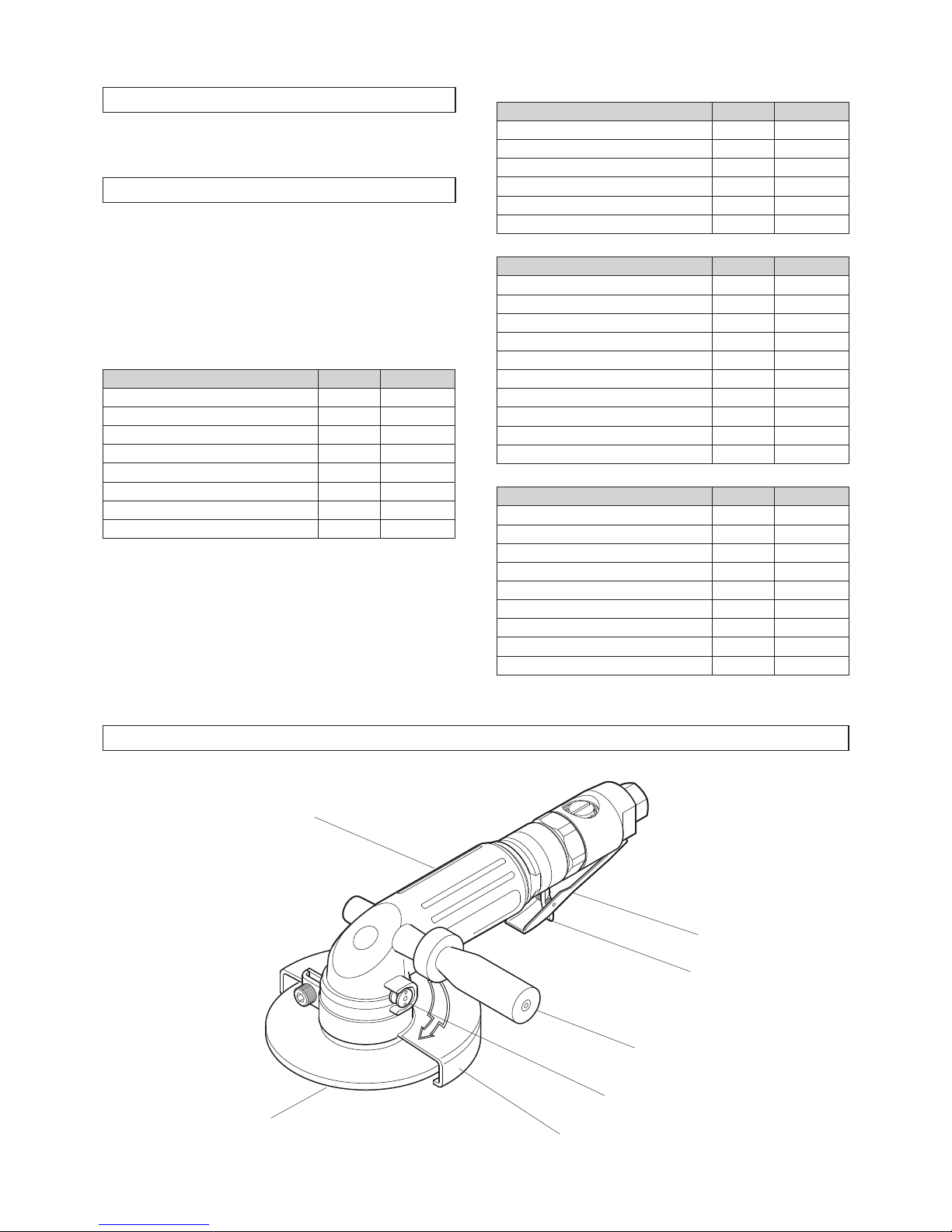
3. NAME OF PARTS
Grinding Wheel
Handle Ass’y
Lock Lever
Spindle Lock Button
Wheel Guard Ass’y
Throttle Lever
Housing
6
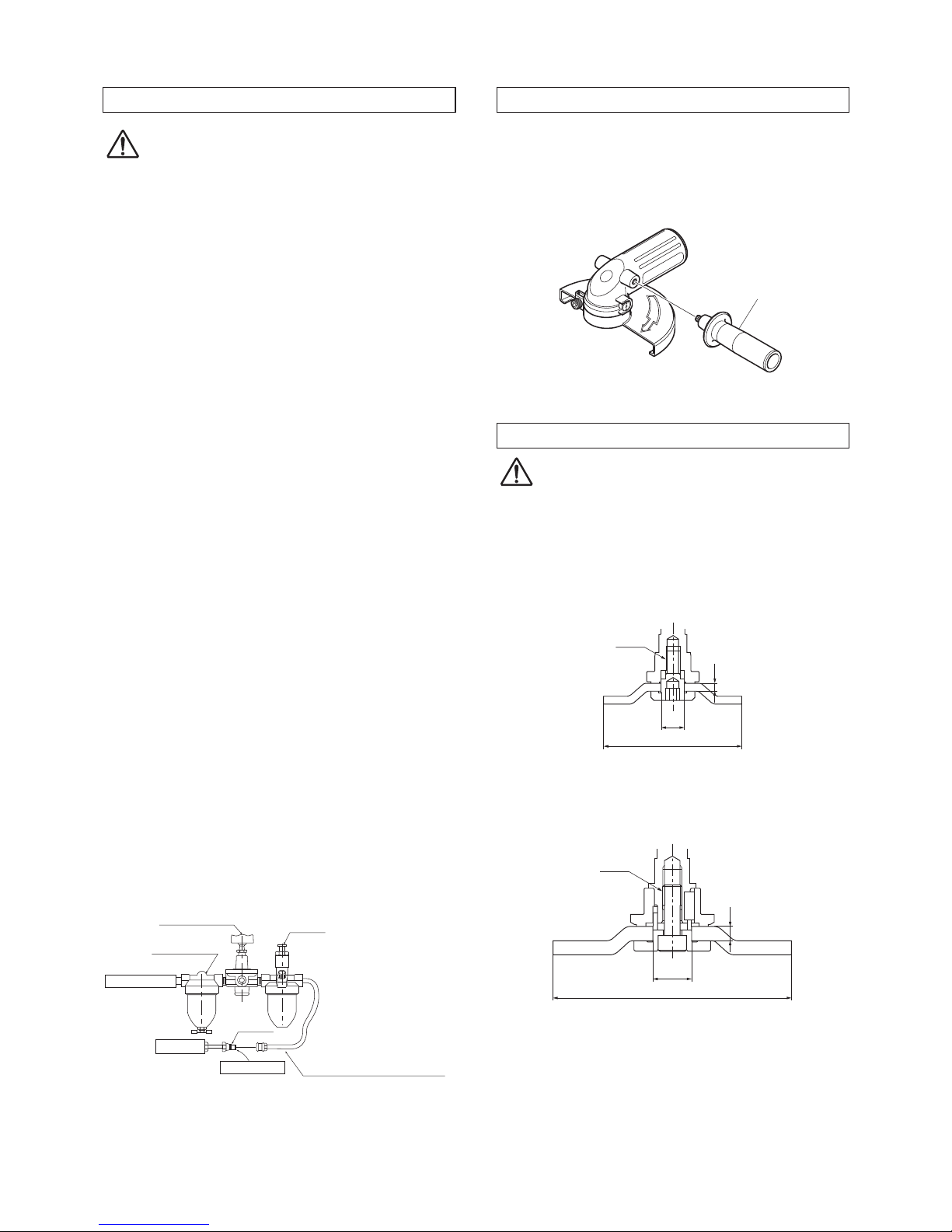
4. AIR SUPPLY
CAUTION
●Draw off drainage before starting operation. If
the drainage enters into the tool, it can freeze
around the exhaust port of the tool and result in
output power reduction.
4-1. Air Pressure
Adjust air pressure to 0.6MPa (or 6 kgf/cm2) with
the air regulator. Lower pressure may result in
insufficient performance. Higher pressure may result
in premature wornout of parts. It is important to
maintain the proper pressure with pressure regulator
on air line.
4-2. Air Line (Fig.2)
Use a 9.5mm (3/8”) I.D. [MLG-25] or 12.7 mm (1/2”)
I.D. [MLG-40, MLG-50, MLG-70] air hose between
the compressor and the tool. Compressed air comes
to be cooled down and its drain be separated, as
soon as the air leaves the compressor. The drain,
however , is condensed in the piping, and can
enter into the tool mechanism, and may cause
malfunction. So, install an air filter and an oiler
between the compressor and the tool.
4-3. oiler
Install an oiler between the compressor and the tool.
Use machine oil ISO VG-10 for lubrication and rust
prevention. Negligence of the oil supply may cause
damages on the tool. Lubricating the tool with high
viscosity oil reduces the tool performance.
4-4. Lubrication (Fig.2)
Before starting the tool, disconnect air hose from
the tool and supply a few drops of machine oil ISO
VG-10 to the air inlet port of the tool. Then reconnect
and make idle running for a few seconds so that the
oil should reach every part in the tool.
Air Regulator Oiler
Air Filter
Compressor
Lubrication
Tool 9.5mm (3/8”) I.D. Hose [MLG-25]
or 12.7mm (1/2”) I.D. Hose
[MLG-40, MLG-50, MLG-70]
Cupla
Fig. 2
5. PREPARATION (MLG-50, MLG-70)
Mounting the Handle Ass’y
Screw the Handle Ass’y into the Housing Sub Ass’
y. It can be mounted on either right or left side of the
Housing Sub Ass’y. Be sure to mount the Handle Ass’
y before use.
+DQGOH$VVҋ\
Fig. 3
6. GRINDING WHEELS
WARNING
The maximum operating speed marked on the Grinding
Wheel, blotters, or packaging, shall equal or exceed
the rated speed on the grinder.
Use with Type 27 Depressed Center Grinding Wheels.
MLG-25
A
M6
B
C
Fig. 4
MLG-40
0
$
%
&
Fig. 5

7
MLG-50
0
0
$
%
&
Fig. 6
MLG-70
0
$
%
&
Fig. 7
MLG-25 MLG-40 MLG-50 MLG-70
A58mm
(2-9/32”) 100mm (4”) 125mm(5”) 180mm (7”)
B9.6mm
(3/8”) 16mm (5/8”) 22mm(7/8”) 22mm (7/8”)
C3mm
(1/8”)
4mm(5/32”)
~
6.4mm(1/4”)
1mm(3/64”)
~
6.4mm(1/4”)
6mm (1/4”)
~
8mm (5/16”)
A : Diameter of the Grinding Wheel
B : Hole of the Grinding Wheel
C : Thickness of the Grinding Wheel
7. MOUNTING AND DISMOUNTING GRINDING WHEEL
WARNING
Always turn off the air supply and disconnect the air
supply hose.
Read and thoroughly understand IMPORTANT
INSTRUCTIONS FOR GRINDER before carrying out
these operations.
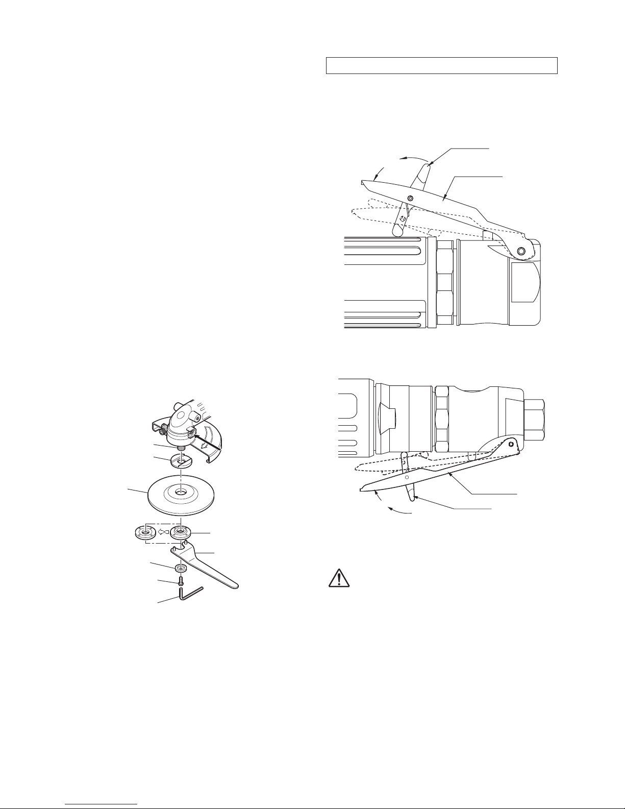
7-1. MLG-25
Mounting
1. Hold the Spindle with Spanner supplied.
2. Insert the Outer Flange into the center hole of the
Grinding Wheel.
3. Secure it firmly to the Spindle by tightening the
Outer Flange with Hex. Socket Screw Key.
Removal
Hold the Spindle with Spanner and loosen Outer
Flange with Hex. Socket Screw Key to remove the
Grinding Wheel.
Spindle
Spanner
Grinding Wheel
Outer Flange
Hex. Socket Screw Key 5
Fig. 8
7-2. MLG-40, MLG-70
Mounting
1. Insert the Outer Flange into the center hole of the
Grinding Wheel.
2. While depressing the Spindle Lock Button lightly,
place the Driving Flange on the Spindle and
rotate it until it comes to stop, then push the
Spindle Lock Button down to the hilt until comes
to lock the position.
3. Align the cutout of the Outer Flange with the
Parallel Key on the Spindle, place the set of the
Outer Flange and the Grinding Wheel on the
Spindle, and tighten it with the accessory Hex.
Socket Screw Key. Releasing your hand from the
Spindle Lock Button will automatically unlock the
Spindle.
Removal
1. While depressing the Spindle Lock Button lightly,
rotate the Grinding Wheel with your hand until it
comes to stop, and then deeply push the Spindle
Lock Button down to the hilt until comes to lock
the position.
2. Loosen the Disk Lock Bolt with the accessory
Hex. Socket Screw Key, and remove the Grinding
Wheel.
'ULYLQJ)ODQJH
6SLQGOH
'HSUHVVWKH6SLQGOH
/RFN%XWWRQ
*ULQGLQJ:KHHO
2XWHU)ODQJH
'LVN/RFN%ROW
+H[6RFNHW6FUHZNH\>0/*@
+H[6RFNHW6FUHZNH\>0/*@
Fig. 9
8
7-3. MLG-50
Mounting
1. Hold the Spindle with pushing the Lock Button.
2. Insert the Driving Flange into the Spindle to fit
the convex on the Spindle and groove of Driving
Flange.
3. Insert the Grinding Wheel and Outer Flange into
the Spindle.
4. In case the thickness of the Grinding Wheel is
4mm or less, attach the Outer Flange up side
down.
5. Secure it firmly to the Spindle by tightening the
Outer Flange with Pin Face Wrench.
6. Secure Washer and Hex. Socket Button Head
Screw 6×15 firmly to the Spindle by tightening
the Socket Button Head Screw 6×15 with Hex.
Socket Screw Key.
Removal
1. Hold the Spindle with pushing the Lock Button.
2. Loosen the Hex. Socket Button Head Screw 6×
15 with Hex. Socket Screw Key and remove the
Washer.
3. Loosen the Outer Flange with the Pin Face
Wrench.
Spindle
Driving Flange
Grinding Wheel
Outer Flange
Pin Face Wrench
4mm or less
Washer
Hex. Socket Screw Key 4
Hex. Socket Button
Head Screw 6×15
Depress the Spindle
Lock Button.
Fig.10
8. HOW TO OPERATE THE TOOL
8-1. Start and Stop
To start, release the lock lever and grasp the throttle
lever.
To stop, release the throttle lever.
MLG-25
Throttle Lever
Lock Lever
Release
Fig. 11
MLG-40, MLG-50, MLG-70
7KURWWOH/HYHU
/RFN/HYHU
5HOHDVH
Fig. 12
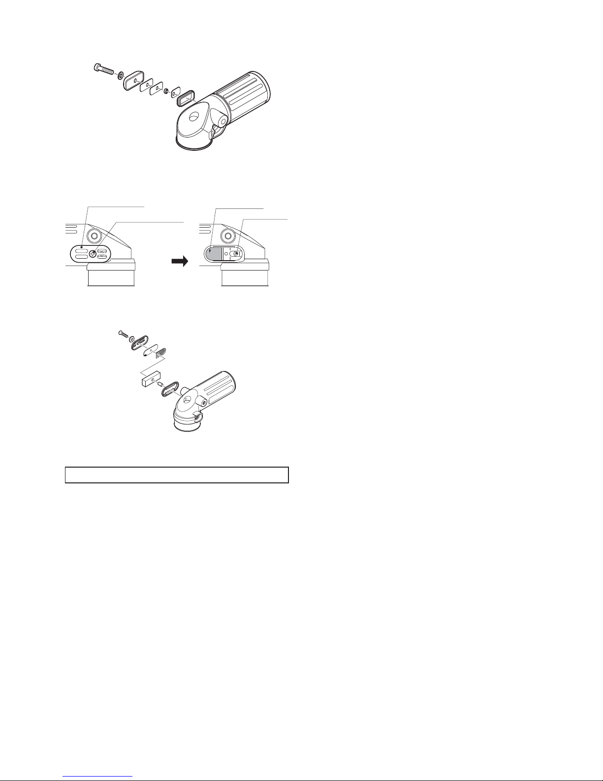
8-2. Adjust Valve
WARNING
Be sure to keep hands clear of moving parts.
The desired number of rotation between maximum rpm
and minimum rpm is obtained by turning the groove of
valve clockwise or counterclockwise with screwdriver.
Maximum rotation
Position the groove of Adjust Valve horizontal to main
body.
Minimum rotation
Position the groove of Adjust Valve vertical to main
body.

9
$GMXVW9DOYH
0D[LPXP
0LQLPXP
Fig. 13
9. STORAGE
CAUTION:
When tool is not used, store it out of reach of
children.
Avoid storing the tool in a location subject to high
humidity. If the tool is left as it is used, residual
moisture on the inside can cause rusting. Before
storing, and after operation, oil the tool at the air inlet
with machine oil ISO VG-10 and run it for a short time.
10. MAINTENANCE
Supply additional appropriate amount of Shell Alvania
Grease S#2 into the Gear Case with about once a
month interval.
MLG-25
1. Loosen the Screw 4x12 and remove the Exhaust
Cover, the Toothed Washer CW-4, the Spacer,
the Exhaust Plate, and the Packing Cover.
2. Inject grease with a grease gun into the Grease
Port next to the Exhaust Port.
The outside diameter of the nozzle tip of the
grease gun must be 3mm or smaller. The nozzle
for grease nipple cannot be used for this grease
filling, because the shape of the Grease Port is
different from that of the nozzle for grease nipple.
3. Before putting back the Exhaust Cover, execute
idle running and wipe out excessive grease.
4. For assembly, see Fig.14 and put back the parts
in the reverse order of disassembly.
(M4 Screw)
Grease Port
Exhaust Port
2. Remove
Spacer
Exhaust Plate
Exhaust Cover
1. Loosen
Screw 4×12
Packing Cover
Toothed Washer CW-4
Fig. 14
Fig. 15
MLG-40, MLG-50, MLG-70
1. Loosen the Screw and remove the Exhaust
Cover, the Toothed Washer CW-4, the Spacer,
and the Exhaust Filter.
2. Inject grease with a grease gun into the Grease
Port next to the Exhaust Port.
The outside diameter of the nozzle tip of the
grease gun must be 4mm or smaller. The nozzle
for grease nipple cannot be used for this grease
filling, because the shape of the Grease Port is
different from that of the nozzle for grease nipple.
3. Before putting back the Exhaust Cover, execute
idle running and wipe out excessive grease.
4. For assembly, see Fig.16~19 and put back the
parts in the reverse order of disassembly.
MLG-40
5HPRYH
/RRVHQ
à 6FUHZð
à 7RRWKHG:DVKHU&:
à ([KDXVW&RYHU
à )LOWHU6XSSRUW
à ([KDXVW)LOWHU
à 6SDFHU *UHDVH3RUW
([KDXVW3RUW
Fig. 16
10
Fig. 17
MLG-50, MLG-70
5HPRYH
/RRVHQ
à 6FUHZð
à 7RRWKHG:DVKHU&:
à 6SDFHU
à ([KDXVW)LOWHU
à ([KDXVW&RYHU ([KDXVW3RUW
*UHDVH3RUW
Fig. 18
Fig. 19
11. ORDERING SERVICE PARTS
●For further operational and handling information or
for replacement of parts and components, contact
the company from whom you purchased the tool or
an authorized dealer.
●In ordering parts and components give each part
number, part name and quantity required.
●Use only NITTO genuine parts.

11
1
24
22 20 19
18
16
15
14
13
12
11
10
9
17
21
2
3
4
5
8
42
76
23
25
26
27
28
29
30
40
38
39
41
36
37
35
34
33
32
31
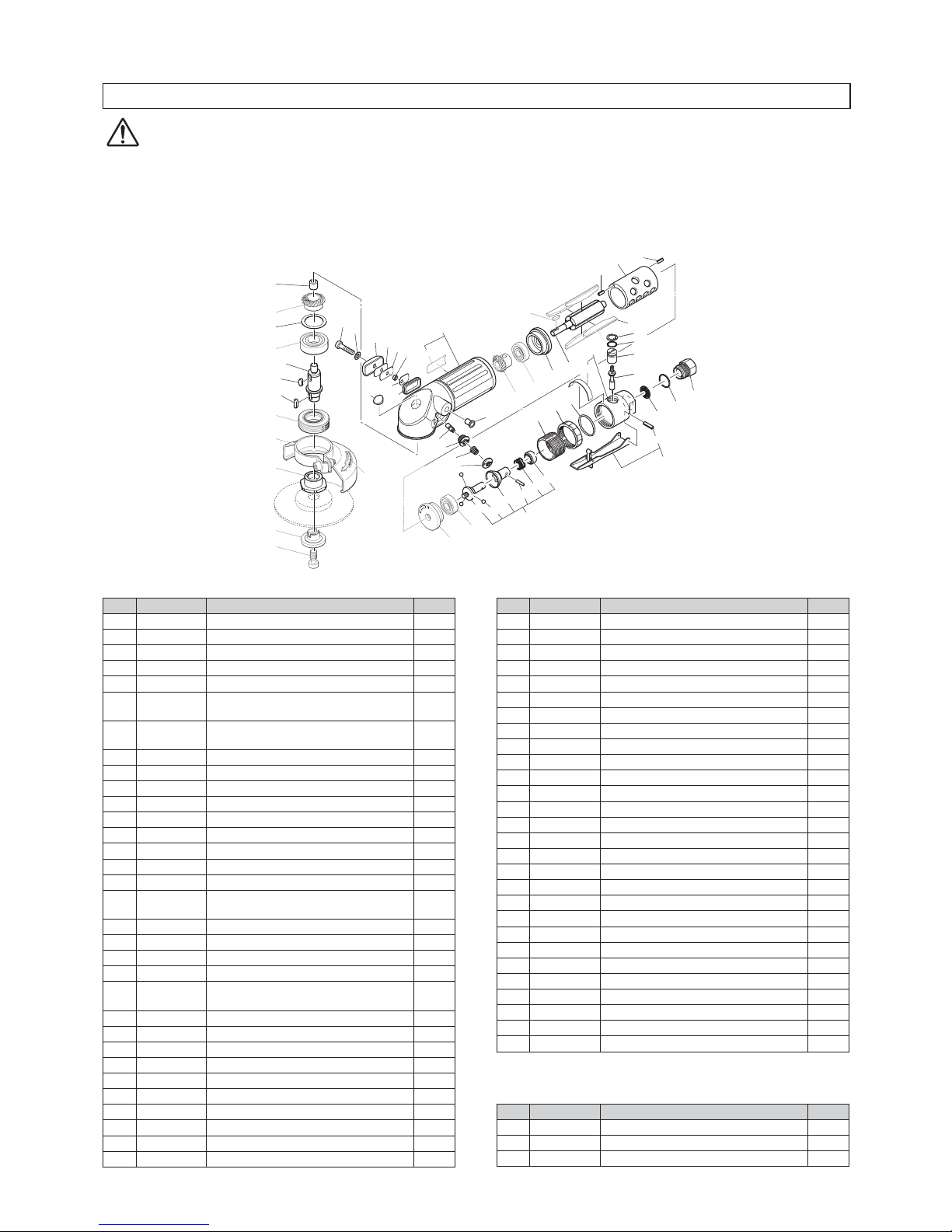
The part numbers with ( ) are included in the Ass’y parts written above them.
No. PartsNo. Description Qty
Price
1 TQ12638 Needle Bearing BK0609T2 1
2 TQ12986 Gear 1×22 1
3 TP00498 Ball Bearing 6001ZZ 1
4 TB08597 Bearing Set Screw Ass'y 1set
5 TQ12620 Spindle 1
6 TB08893 Wheel Guard Ass'y 1set
7 (TQ13054) Label Warning Wheel Guard 1
8 TP17962 Outer Flange 1
9 TP14222 Cylinder 1
10 TB08602 Blade Ass'y (4 pcs.) 1set
11 TP14224 Rotor 1
12 TQ12622 End Plate B 1
13 TP06322 Spacer 8×11×3 1
14 TP00468 Ball Bearing 608ZZ 1
15 TQ12985 Pinion 1×15 1
16 TB08892 Housing Ass'y 1set
17 (TQ13052) Label Warning CE Mark 1
18 TQ12628 Plug 1
19 TQ12649 Packing Cover 1
20 TQ12630 Exhaust Plate 2
21 TQ12658 Spacer 4EP-3 1
22 TQ12629 Exhaust Cover 1
23 TQ12647 Toothed Washer CW-4 1
24 TQ12739 Raised Countersunk Head
Screw 4×12 1
No. PartsNo. Description Qty
Price
25 TP00496 Spring Pin 2.5×6 AW 1
26 TP10109 End Plate A 1
27 TP03933 Ball Bearing 606ZZ 1
28 TP10110 Cap 1
29 TP10098 Lock Nut 1
30 TP03468 Lock Ring 1
31 TP03695 Internal Retaining Ring C-12 1
32 TP06326 Spacer 6×12×1.2 1
33 TP11997 O-Ring KS-7 1
34 TP06325 Adjust Valve 1
35 TA93070 Valve Stem Ass'y 1set
36 TB08895 Valve Body Sub Ass'y 1set
37 (TQ13053) Label Model 1
38 TB01152 Lever Ass'y 1set
39 (TP00460) Spring Pin 3×22 AW 1
40 (TP05498) Spring Pin 2×16 AW 1
Accessories
No. PartsNo. Description Qty
Price
41 TP02236 Bushing R1/4xNPT1/4 1
42 −Grinding Wheel GS#80×58 1
TQ12633 Single Ended Spanner 19 1
TP04004 Hex. Socket Screw Key 5 1
TQ12673 Instruction Manual 1
12. EXPLODED DIAGRAM : MLG-25
WARNING
This diagram is for your reference only. Do not attempt to service or repair the Tool.
Do not take the Tool apart. Contact an authorized Nitto dealer for all service and repair of the Tool.
Improper service and repair can cause accidents and service injuries.
Never attempt to modify the Tool.
Never attempt service or repair the Tool yourself.
12
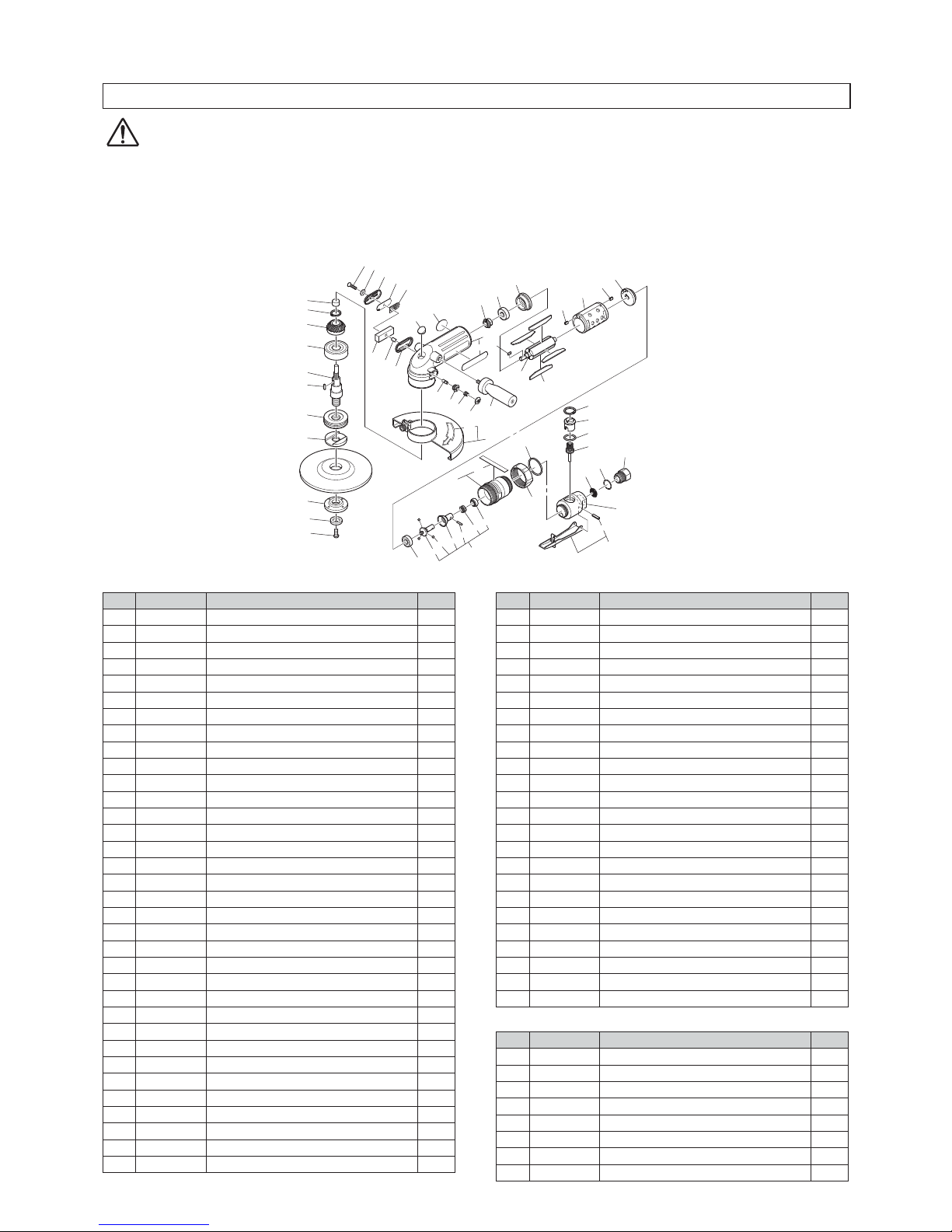
13. EXPLODED DIAGRAM : MLG-40
WARNING
This diagram is for your reference only. Do not attempt to service or repair the Tool.
Do not take the Tool apart. Contact an authorized Nitto dealer for all service and repair of the Tool.
Improper service and repair can cause accidents and service injuries.
Never attempt to modify the Tool.
Never attempt service or repair the Tool yourself.
(41)
(42)
(43)
(44)
(45)
(46)
48
1
2
3
4
5
6
7
8
9
11
12
13
(10)
22 23
24
26
25
27
29
28
30
(32)
31
17
21 20
19
18
16
14
14
15
34
35
36
37
38
39
40
47
49
(33)
50
(51)
52
(53)
55
54
56
57
58
59
60
The part numbers with ( ) are included in the Ass’y parts written above them.
No. PartsNo. Description Qty
1 TQ00893 Needle Bearing BK0810 1
2 TQ12725 Gear 1
3 TQ12887 Plate 13.1x30x1.2 1
4 TP01609 Ball Bearing 6202ZZ 1
5 TQ13048 Spindle 1
6 TP00502 Parallel key Both Ends
Round 4x4x9.5 1
7 TQ13516 Grooved Parallel key Both Ends
Round 4x4x12 1
8 TB08883 Bearing Set Screw Ass’y 1set
9 TB08918 Wheel Guard Ass’y 1set
10 (TQ02357) Label Warning for Wheel Guard 1
11 TQ13049 Driving Flange 1
12 TQ00775 Outer Flange 1
13 TP09932 Disk Lock Bolt 1
14 TP04061 Spring Pin 3x6 2
15 TQ13033 Cylinder 1
16 TB08707 Blade Ass’y(4pcs.) 1set
17 TP10130 Parallel key Both Ends
Round 3x3x10 1
18 TQ13032 Rotor 1
19 TQ13030 EndPlate B 1
20 TP10133 Ball Bearing 609ZZ 1
21 TQ12726 Pinion 1
22 TQ12739 Raised Countersunk Head Screw
4x12 1
23 TQ12647 Toothed Washer CW-4 1
24 TQ12729 Exhaust Cover 1
25 TQ13038 Filter Support 40 1
26 TQ13039 Exhaust Filter 40 1
27 TQ13036 Spacer 4.3x8x2.8 1
28 TQ13037 Exhaust Plate 1
29 TQ12730 Packing Cover 1
30 TQ12724 Plug 40 1
31 TB08702 Housing SUB Ass’y 1set
32 (TQ12774) Label Warning CE Marking 1
No. PartsNo. Description Qty
33 (TQ13074) Plug 7.2 1
34 TQ12542 Lock Pin 1
35 TQ12537 Pin Guide 1
36 TQ12544 Conical Spring 0.6x7.2x8.8x8 1
37 TQ12543 Lock Button 1
38 TQ13029 EndPlate A 1
39 TQ12782 Ball Bearing 699ZZ 1
40 TB08676 Governor Ass’y 1set
41 (TQ12813) Base 1
42 (CP03282) Ball 7/32 3
43 (TQ12067) Sleeve 1
44 (TQ12090) Needle Roller 2.5x13.8 1
45 (TQ13035) Spring 1.4x15.5x16.3 1
46 (TQ12068) Stopper 1
47 TQ12777 Adapter 1
48 TQ12778 Lock Ring 1
49 TQ12780 O-ring JASO-1033 1
50 TB08704 Valve Body Ass’y 1set
51 (TQ12776) Label Model 1
52 TB08669 Lever Ass’y 1set
53 (TP13893) Spring Pin 3x22AW 1
54 TP03473 Internal Retaining Ring C-14 1
55 TP11992 O-ring KS-9 1
56 TP04394 Adjust Valve 1
57 TB05591 Throttle Valve Ass’y 1set
58 TP01658 Filter 1
59 CP25821 O-ring JASO-1020 1
60 TQ12671 Bushing M23xRc3/8 1
Accessories
No. PartsNo. Description Qty
TP00170 Hex.Socket Screw Key 6 1
TQ12673 Instruction Manual 1
TQ02350 Bushing R3/8xNPT3/8 1
13
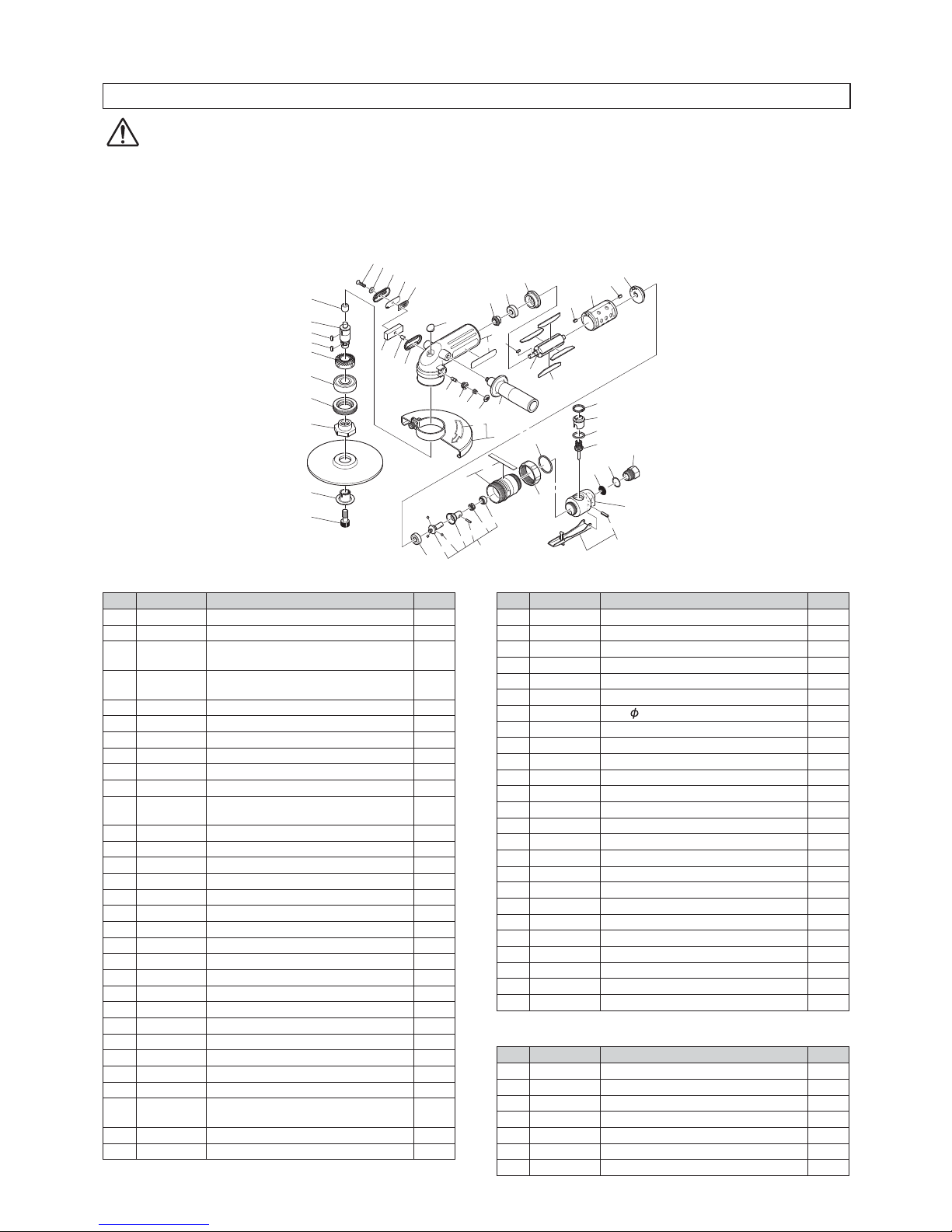
14. EXPLODED DIAGRAM : MLG-50
WARNING
This diagram is for your reference only. Do not attempt to service or repair the Tool.
Do not take the Tool apart. Contact an authorized Nitto dealer for all service and repair of the Tool.
Improper service and repair can cause accidents and service injuries.
Never attempt to modify the Tool.
Never attempt service or repair the Tool yourself.
The part numbers with ( ) are included in the Ass’y parts written above them.
1
2
3
4
5
6
7
8
9
10
11
12
14
15
16
19
18
17
20
31
30
(22)
32
33
34
35
36
37
37
38
39
29
24
25
23
26
27
(28)
51
50
(21)
40
(43)
(42)
(44)
(45)
41
(46)
(47)
(49)
48
(54)
53
52
55
56
57
58
61
59
13
60
No. PartsNo. Parts Name Qty
1 TQ12088 Needle Bearing BK1012 1
2 TP18356 External Retaining Ring C-14 1
3 TQ14290 Gear 1
4 TP04138 Ball Bearing 6204ZZ 1
5 TQ14289 Spindle 1
6 TP09933 Parallel Key Both Ends Round 4X4X12 1
7 TB12073 Bearing Set Screw Ass'y 1set
8 TQ04123 Driving Flange 1
9 TQ04124 Outer Flange 1
10 TQ04139 Wahser 6.3x21x4.5 1
11 TP14688 Hex. Socket Button Head Screw 6x15 1
12 TQ12330 Raised Countersunk Head Screw 4x20 1
13 TQ12647 Toothed Washer CW-4 1
14 TQ12076 Exhaust Cover 1
15 TQ12570 Filter Support 1
16 TQ12541 Silencer Plate 1
17 TQ12540 Exhaust Filter 1
18 TQ12109 Spacer 5x6x11.8 1
19 TQ12559 Packing Cover 1
20 TB09676 Housing Sub Ass'y 1set
21 (TQ12663) Label Warning CE Marking 1
22 (TQ14301) Label Model 1
23 TQ12542 Lock Pin 1
24 TQ12537 Pin Guide 1
25 TQ12544 Conical Spring 0.6x7.2x8.8x8 1
26 TQ12543 Lock Button 1
30 TQ12571 Plug 1
31 TQ14288 Pinion 1
32 TQ12087 Ball Bearing 638ZZ 1
33 TQ12064 EndPlate B 1
34 TP10130 Parallel Key Both Ends Round 3x3x10 1
35 TQ12061 Rotor 1
36 TB08555 Blade Ass'y 1set
37 TP04061 SpringPin 3x6 AW 2
No. PartsNo. Parts Name Qty
38 TQ12062 Cylinder 1
39 TQ12063 EndPlate A 1
40 TP06242 Ball Bearing 629ZZ 1
41 TB08258 Governor Ass'y 1set
42 (TQ12066) Base 1
43 (TP01566) Ball φ63
44 (TQ12067) Sleeve 1
45 (TQ12090) Needle Roller 2.5x13.8 1
46 (TQ12069) Spring 1.4x15.5x15.5 1
47 (TQ12068) Stopper 1
48 TB09678 Valve Holder Ass’y 1set
49 (TQ14292) Label Specification 1
50 TP17452 Lock Ring 1
51 TP17445 O-ring S-35.5 1
52 TQ12662 Valve Body 1
53 TB08669 Lever Ass'y 1set
54 (TP13893) SpringPin 3x30AW 1
55 TP10448 Internal Retaining Ring C-24 1
56 TQ12668 Adjust Valve 1
57 TP10714 O-ring S-22 1
58 TB09001 Valve Stem Ass'y 1set
59 TP01658 Filter 1
60 CP25821 O-ring JASO-1020 1
61 TQ12671 Bushing M23xRc3/8 1
Accessories
No. PartsNo. Parts Name Qty
27 TB09681 Wheel guard Ass'y 1set
28 (TQ04121) Label Warning Wheel guard 1
29 TB09680 Side Handle Ass'y 1set
TP00170 Hex. Socket Screw Key 6 1
TP01939 Hex. Socket Screw Key 4 1
TQ04125 Pin Face Wrench 1
TQ02350 Bushing R3/8xNPT3/8 1
TQ12673 Instruction Manual 1
14
15. EXPLODED DIAGRAM : MLG-70
WARNING
This diagram is for your reference only. Do not attempt to service or repair the Tool.
Do not take the Tool apart. Contact an authorized Nitto dealer for all service and repair of the Tool.
Improper service and repair can cause accidents and service injuries.
Never attempt to modify the Tool.
Never attempt service or repair the Tool yourself.
1
10
12
13
14
17
16
15
18
28
27
29
30
31
32
33
34
34
35
36
26
21 22
20
23
24
(25)
48
47
(19)
2
3
59
4
5
6
7
37
(40)
(39)
(41)
(42)
38
(43)
(44)
(46)
45
(51)
50
49
52
53
54
55
58
56
8
9
11
57
The part numbers with ( ) are included in the Ass’y parts written above them.
No. PartsNo. Description Qty
1 TQ12088 Needle Bearing BK1012 1
2 TQ12546 Spindle 1
3 TP09933 Parallel Key Both Ends Round
4X4X12 1
59 TQ13516 Grooved Parallel Key Both Ends
Round 4X4X12 1
4 TQ12547 Gear 1
5 TP04138 Ball Bearing 6204ZZ 1
6 TB08263 Bearing Set Screw Ass'y 1set
7 TQ00772 Driving Flange 1
8 TQ00771 Outer Flange 1
9 TP11688 Disk Lock Bolt 1
10 TQ12330 Raised Countersunk Head Screw
4X20 1
11 TQ12647 Toothed Washer CW-4 1
12 TQ12076 Exhaust Cover 1
13 TQ12570 Filter Support 1
14 TQ12541 Silencer Plate 1
15 TQ12540 Exhaust Filter 1
16 TQ12109 Spacer 5X6X11.8 1
17 TQ12559 Packing Cover 1
18 TB08793 Housing SUB Ass'y 1set
19 (TQ12663) Label Warning CE Marking 1
20 TQ12542 Lock Pin 1
21 TQ12537 Pin Guide 1
22 TQ12544 Conical Spring 0.6X7.2X8.8X8 1
23 TQ12543 Lock Button 1
27 TQ12571 Plug 1
28 TQ12070 Pinion 1
29 TQ12087 Ball Bearing 638ZZ 1
30 TQ12064 EndPlate B 1
31 TP10130 Parallel Key Both Ends Round
3X3X10 1
32 TQ12061 Rotor 1
33 TB08555 Blade Ass'y 1set
No. PartsNo. Description Qty
34 TP04061 SpringPin 3X 6 AW 2
35 TQ12062 Cylinder 1
36 TQ12063 EndPlate A 1
37 TP06242 Ball Bearing 629ZZ 1
38 TB08258 Governor Ass'y 1set
39 (TQ12066) Base 1
40 (TP01566) Ball 63
41 (TQ12067) Sleeve 1
42 (TQ12090) Needle Roller 2.5X13.8 1
43 (TQ12069) Spring 1.4X15.5X15.5 1
44 (TQ12068) Stopper 1
45 TB08668 Valve Holder Ass’y 1set
46 (TQ12750) Label Model 1
47 TP17452 Lock Ring 1
48 TP17445 O-ring S-35.5 1
49 TQ12662 Valve Body 1
50 TB08669 Lever Ass'y 1set
51 (TP13893) SpringPin 3X30AW 1
52 TP10448 Internal Retaining Ring C-24 1
53 TQ12668 Adjust Valve 1
54 TP10714 O-ring S-22 1
55 TA96331 Valve Stem Ass'y 1set
56 TP01658 Filter 1
57 CP25821 O-ring JASO-1020 1
58 TQ12671 Bushing M23XRc3/8 1
Accessories
No. PartsNo. Description Qty
24 TB08757 Wheel guard Ass'y 1set
25 (TQ12640) Label Warning Wheel guard 1
26 TB08265 Handle Ass'y 1set
TP00170 Hex. Socket Screw Key 6 1
TP11723 Hex. Socket Screw Key 10 1
TQ02350 Bushing R3/8XNPT3/8 1
TQ12673 Instruction Manual 1

Printed in KOREA TQ12673-6
2YHUVHDV$IILOLDWHV2IILFHV
1,772.2+.,86$,1&
&KDQFHOORU'ULYH5RVHOOH,/86$
7HO )D[
1,772.2+.,(8523(&2/7'
8QLW7KH(PSLUH&HQWUH,PSHULDO:D\
:DWIRUG+HUWV:'768.
7HO )D[
1,772.2+.,'(876&+/$1'*0%+
/HUFKHQVWU'6WHLQHQEURQQ*HUPDQ\
7HO )D[
1,772.2+.,&2/7'6,1*$325(%5$1&+
8%,&5(6&(17
8%,7(&+3$5./2%%<'6,1*$325(
7HO )D[
1,772.2+.,&2/7'
%$1*.2.5(35(6(17$7,9(2)),&(
0$%XVLQHVV&HQWHU4+RXVH&RQYHQW%OGJ
WK)ORRU8QLW$&RQYHQW5G6LORP%DQJUDN
%DQJNRN7KDLODQG
7HO )D[
1,772.2+.,$8675$/,$37</7'
%UDQGO6W%ULVEDQH7HFKQRORJ\3DUN
(LJKW0LOH3ODLQV4/'$XVWUDOLD
7HO )D[
1,772.2+.,6+$1*+$,&2/7'
5RRPVXLWH&2ULHQW,QWHUQDWLRQDO3OD]D
12/RX6KDQ*XDQ5RDG6KDQJKDL&+,1$
7HO )D[
1,772.2+.,&2/7'
6+(1=+(15(35(6(17$7,9(2)),&(
&6KHQ]KHQ,&&7RZHU)XKXDVDQOX)XWLDQ'LVWULFW
6KHQ]KHQ*XDQJGRQJ&KLQD
7HO )D[
This manual suits for next models
5
Table of contents
Other Nitto Grinder manuals


Popular Grinder manuals by other brands

Flex
Flex L 8-11 125 operating instructions

OPTIMUM Maschinen
OPTIMUM Maschinen OPTIgrind GBS 75 operating manual

EINHELL
EINHELL TC-WD 150 operating instructions

DeWalt
DeWalt DW756 instruction manual

Parkside
Parkside PWSA 20-Li C3 Translation of the original instructions

Makita
Makita DGA411 instruction manual


