NKT Photonics Koheras ADJUSTIK User manual
Koheras ADJUSTIK
PRODUCT GUIDE
Low Noise Single Frequency Laser System

PRODUCT GUIDE
This guide includes the following NKT Photonics Lasers:
Koheras ADJUSTIK
Low Noise Single Frequency Laser System
Koheras ADJUSTIK Product Guide Revision 1.0 01-2020 W-10456

3
GUIDE OVERVIEW
This product guide is intended to provide functional, operational and installation
information for the Koheras ADJUSTIK laser modules. The guide is divided into
three sections:
• Koheras Low Noise Single Frequency Laser System Description -
introduces the laser, its functionality, interfaces and chassis variants.
• Operating the Laser – – provides information and procedures on how to
connect, configure and manage the laser.
• Installing the Laser – includes the details on how to install the laser and
connect optional interfaces.
Warning: Do not operate the laser before first reading and understanding all
warnings, cautions and handling information stated within the document:
Koheras ADJUSTIK Safety, Handling and Regulatory Information
Note: The paper copy of this document is included with your laser; however, it
can also be downloaded from:
https://www.nktphotonics.com/lasers-fibers/support/product-manuals/
Terminology This guide may refer to the Koheras ADJUSTIK as “the laser”. In specific cases
where a distinction is required, this guide will use the actual laser model names.
Target audience This guide is for technical personnel involved in the selection, planning and
deployment of lasers in laboratory and industrial settings. The guide assumes a
reasonable knowledge level of lasers, photonic principles and electrical interface
connectivity.
Chapters inside This guide includes the following chapters:
• Chapter I “Laser Description” — Describes the laser including its general
operational principles, management and interfaces.
• Chapter 2 “Modulation” — Implementation information for wavelength and
amplitude modulation.
• Chapter 3 “Communicating with the Laser” — Provides information and
procedures on how to setup a PC with the laser’s management software and
connect it to the laser.
• Chapter 4 “Turning ON the Laser” — Contains procedures on how to safely
turn the laser emissions on and off using the management software.

4
• Chapter 5 “Using CONTROL” — Includes descriptions of all NKT CONTROL
menu, settings, and panel items.
• Chapter 6 “Mechanical Installation” — Includes information and procedures
on how to correctly install the laser chassis. Procedures within this chapter
focus on providing adequate temperature regulation.
• Chapter 7 “Connecting the Laser” — This chapter provides the information on
how to physically connect the safety interlock, power, the optical
connections, and the .
• Appendices — The guide includes multiple appendices including laser
specifications, support contact details, accessory descriptions and
miscellaneous procedures supporting the laser operation and installation.
Added information
and safety notices
Lasers are highly dangerous devices that can cause serious injury and property
damage. This guide use the following symbols to either highlight important safety
information or provide further information in relation to a specific topic.
Note: Highlights additional information related to the associated topic and/or
provides links or the name of the NKT guides describing the additional informa-
tion.
Caution: Alerts you to a potential hazard that could cause loss of data, or damage
the system or equipment.
Warning: The laser safety warning alerts you to potential serious injury that may
be caused when using the laser.
Revision The section records the document revision details.
January 2020 – First release - the document has been rewritten and overhauled
from earlier releases.

5
CONTENTS
Guide Overview ................................................................................................................... 3
Terminology ............................................................................................................ 3
TABLES .....................................................................................................................11
FIGURES ..................................................................................................................13
PROCEDURES ....................................................................................................... 15
Section 1 KOHERAS ADJUSTIK DESCRIPTION 17
1 Laser Description ...............................................................................................................19
Features and Options ......................................................................................... 19
Theory of operation ........................................................................................... 20
Module variants ........................................................................................................ 20
Center wavelength ............................................................................................. 20
Output power ....................................................................................................... 20
Tuning types ......................................................................................................... 21
Front and rear panels ............................................................................................... 21
Front panel ............................................................................................................ 21
Rear panel .............................................................................................................23
Optical specifications .............................................................................................. 23
Laser features ........................................................................................................... 24
Thermal tuning .................................................................................................... 24
Fast wavelength modulation ........................................................................... 24
External cavity stabilization .............................................................................. 25
Amplitude modulation ....................................................................................... 25
.Operating mode ................................................................................................. 25
Trigger ................................................................................................................... 26
Auto-start .............................................................................................................. 26
High temperature shutdown ............................................................................ 26
Power verification ................................................................................................27

6
Miscellaneous ............................................................................................................ 27
Safety ..................................................................................................................... 27
Optical interface ........................................................................................................ 27
Optical fibers, connectors and adapters ...................................................... 27
Laser Control ............................................................................................................. 28
User interface ...................................................................................................... 28
Status LEDs ................................................................................................................29
Chassis labels ............................................................................................................ 30
2 Modulation ..........................................................................................................................33
Fast wavelength modulation ................................................................................. 33
Configuring external and internal wavelength modulation ..................... 33
Wavelength+/- signal ......................................................................................... 34
Differential input .................................................................................................. 35
Single-ended to differential ............................................................................. 35
Singled-ended input .......................................................................................... 35
Wavelength- to GND ...........................................................................................37
Differential output ............................................................................................... 38
Wavelength modulation coupling .................................................................. 38
Narrow vs. Wide modulation range ............................................................... 38
Frequency response .......................................................................................... 38
Amplitude modulation .............................................................................................40
Amplitude+/- Signal ............................................................................................ 40
External cavity stabilization (ADJUSTIK X15) ...................................................... 41
Setting up external cavity stabilization ......................................................... 42
Section 2 OPERATING THE LASER 43
2 Front Panel Menu ............................................................................................................. 45
Overview ..................................................................................................................... 45
General operation ............................................................................................... 45
Top menu .............................................................................................................. 46
Wavelength .......................................................................................................... 46

7
Wavelength display .............................................................................................47
W1 modulation ......................................................................................................47
W1 mod. Gain ........................................................................................................47
W1 mod. source ....................................................................................................48
W1 mod. Coupling ................................................................................................48
W1 mod. Range .....................................................................................................48
Power /current mode ......................................................................................... 49
Power ..................................................................................................................... 49
Power unit ............................................................................................................. 49
Watchdog timer ................................................................................................... 50
Display backlight ................................................................................................. 50
IP Address ............................................................................................................ 50
Emission button ................................................................................................... 50
3 Communicating with the Laser ......................................................................................53
CONTROL software ................................................................................................. 53
Installing the software ....................................................................................... 53
Connecting the laser to a PC with CONTROL .................................................. 53
Ethernet connection .......................................................................................... 54
4 Turning ON the Laser .......................................................................................................57
Safety ............................................................................................................................57
Preparation .................................................................................................................57
Enabling and disabling emission .......................................................................... 58
Enable emission (CONTROL) ........................................................................... 58
Enable emission (front panel) .......................................................................... 59
5 Using CONTROL ...............................................................................................................63
CONTROL overview ................................................................................................ 63
Relocating panels ............................................................................................... 64
Toggling panels .................................................................................................. 65
Connecting to the laser .................................................................................... 65
Status panel ............................................................................................................... 65
Status indicators ................................................................................................. 66

8
System info ........................................................................................................... 67
Measurements ..................................................................................................... 67
WL mod button and indicator .......................................................................... 67
Emission button ................................................................................................... 67
CONTROL settings ................................................................................................... 67
Wavelength modulation .................................................................................... 68
Power/Current mode ...........................................................................................71
Ethernet ................................................................................................................. 72
Watchdog .............................................................................................................. 72
Clock .......................................................................................................................73
View .........................................................................................................................74
CONTROL menu items ............................................................................................ 74
Serial monitor ........................................................................................................74
Application log ..................................................................................................... 75
CONTROL – Control panel .................................................................................... 76
Power mode ......................................................................................................... 76
Current mode ....................................................................................................... 76
Section 3 INSTALLING THE LASER 77
6 Mechanical Installation ....................................................................................................79
General ........................................................................................................................ 79
Heat dissipation ........................................................................................................ 79
Rack mounting the laser ......................................................................................... 79
Placing the laser on a table or shelf ....................................................................80
Operating and storage environment .............................................................. 81
7 Connecting the Laser ...................................................................................................... 83
Connecting the safety interlock ............................................................................ 83
Interlock operation ............................................................................................. 83
Connecting an interlock switch ....................................................................... 84
Bus defeater ......................................................................................................... 84
Connecting power .................................................................................................... 85

9
Connecting modulation signals ............................................................................ 85
Connecting the trigger input or output ............................................................... 85
Input trigger .......................................................................................................... 85
Output trigger ...................................................................................................... 86
Connecting the optical output .............................................................................. 86
Appendices
A Specifications ......................................................................................................................91
B Service and support Information .................................................................................. 95
Servicing the laser ................................................................................................... 95
Opening the laser chassis ................................................................................ 95
WARRANTY VOID IF REMOVED Label ......................................................... 95
Support contact details ........................................................................................... 96
Support Email ...................................................................................................... 96
Online support web-page ................................................................................ 96
Shipping address ................................................................................................ 96
C Interface Pin Assignments ..............................................................................................97
Modulation input/output ..........................................................................................97
External bus ...............................................................................................................97
D CONTROL Software ........................................................................................................ 99
Installing CONTROL ................................................................................................. 99

10

11
TABLES
Table 1: ADJUSTIK variant specifications....................................................................... 20
Table 2: ADJUSTIK rear panel layout ............................................................................. 23
Table 3: Recommended power modes .......................................................................... 25
Table 4: Optical Interface Specifications ...................................................................... 28
Table 5: Status LEDs............................................................................................................ 29
Table 6: Module labels......................................................................................................... 31
Table 7: Wavelength modulation settings ..................................................................... 34
Table 8: Narrow vs wide band wavelength modulation............................................. 38
Table 9: Front panel menu items ..................................................................................... 45
Table 10: CONTROL panels and menu items ............................................................... 63
Table 11: Power specifications........................................................................................... 85
Table 12: Optical ................................................................................................................... 91
Table 13: Mechanical dimensions .................................................................................... 91
Table 14: Operating and storage environment ............................................................. 91
Table 15: Electrical................................................................................................................ 92
Table 16: Safety and regulatory compliances .............................................................. 92
Table 17: Mechanical dimensions..................................................................................... 93
Table 18: Modulation connector pin assignment ..........................................................97
Table 19: External bus pin assignment ............................................................................97

12

13
FIGURES
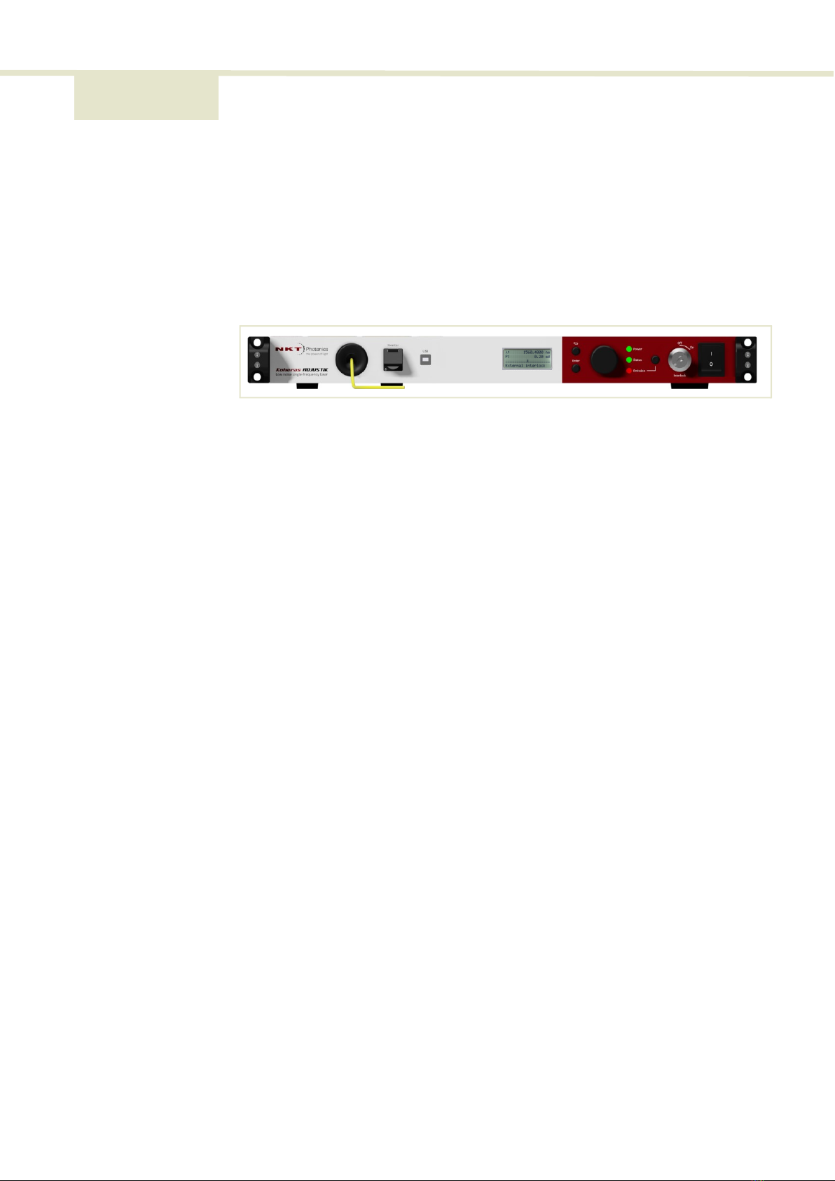
Figure 1: ADJUSTIK front panel ........................................................................................ 19
Figure 2: ADJUSTIK front panel layout .......................................................................... 22
Figure 3: Frequency response using wavelength modulation ................................ 24
Figure 4: Top panel label locations ................................................................................ 30
Figure 5: Rear panel label location ................................................................................. 30
Figure 6: Differential input signal for wavelength modulation ................................ 35
Figure 7: Single-ended to differential ............................................................................ 35
Figure 8: Single-ended input signal with 2.5 V ........................................................... 36
Figure 9: Single-ended input with 2.5 V on an unused branch .............................. 36
Figure 10: Single-ended input signal with GND on an unused branch ..................37
Figure 11: Single-ended input connections with 0 V on an unused branch ..........37
Figure 12: Differential output signal ................................................................................ 38
Figure 13: ADJUSTIK X15 wavelength modulation response .................................. 39
Figure 14: ADJUSTIK E15/C15/Y10 wavelength modulation response .................. 40
Figure 15: Differential input for amplitude modulation ............................................... 41
Figure 16: Single-ended input for amplitude modulation .......................................... 41
Figure 17: ADJUSTIK X15 in Pound-Drever-Hall configuration ................................ 42
Figure 18: Top level menu ................................................................................................. 46
Figure 19: Wavelength setting menu ...............................................................................47
Figure 20: Wavelength display menu - set as Absolute ............................................47
Figure 21: Wavelength modulation - ON ........................................................................47
Figure 22: Wavelength modulation gain setting menu ............................................. 48
Figure 23: Wavelength modulation source signal set to internal ........................... 48
Figure 24: Wavelength modulation signal coupling set to AC ................................ 48
Figure 25: Wavelength modulation range set to Narrow ......................................... 48
Figure 26: Operation mode set to constant power mode ........................................ 49
Figure 27: Power tuning menu ........................................................................................ 49
Figure 28: Power unit menu - set to mW ...................................................................... 49
Figure 29: Watchdog timer setting ................................................................................. 50

14
Figure 30: Setting the intensity level of the LCD panel back light .........................50
Figure 31: IP address setting .............................................................................................50
Figure 32: GUI panel navigation ...................................................................................... 63
Figure 33: Panel dragged to a new location in the main window - ....................... 64
Figure 34: Panels dragged outside the main window ............................................... 64
Figure 35: Panels dragged outside the main window ...............................................65
Figure 36: Welcome screen and connecting ...............................................................65
Figure 37: Status panel ......................................................................................................66
Figure 38: GUI settings ...................................................................................................... 68
Figure 39: Wavelength modulation - internal source ................................................. 69
Figure 40: Wavelength modulation - external source ...............................................69
Figure 41: Internal generator waveform selection (Type) ..........................................69
Figure 42: Turning on wavelength modulation ............................................................ 71
Figure 43: Power and current mode controls ............................................................... 71
Figure 44: Ethernet setting ................................................................................................ 72
Figure 45: Watchdog setting ............................................................................................ 73
Figure 46: Clock setting ..................................................................................................... 73
Figure 47: View setting ...................................................................................................... 74
Figure 48: Menu items ....................................................................................................... 74
Figure 49: Serial monitor ................................................................................................... 75
Figure 50: Serial Monitor ................................................................................................... 75
Figure 51: Operating mode set to power ...................................................................... 76
Figure 52: Rear panel heat sink ....................................................................................... 79
Figure 53: Image of the laser rack mounted ................................................................80
Figure 54: Rubber mounting feet .....................................................................................81
Figure 55: Table or shelf mounting ................................................................................. 81
Figure 56: Interlock connected to a door switch - Laser ON ................................... 83
Figure 57: Interlock connected to a door switch - Laser SHUTDOWN ................. 84
Figure 58: Trigger input circuit .........................................................................................86
Figure 59: Trigger output circuit ...................................................................................... 86
Figure 60: Warranty seal ...................................................................................................95
white

15
PROCEDURES
Procedure 1: Connecting a PC to the laser using a USB cable ............................... 53
Procedure 2: Connecting a PC to the laser using Ethernet ..................................... 55
Procedure 3: Turning on the laser using CONTROL.................................................. 58
Procedure 4: Turning on the laser using CONTRO4 ................................................. 60
Procedure 5: Relocating panels ...................................................................................... 64
Procedure 6: Connecting the door interlock circuit................................................... 84
Procedure 7: Installing CONTROL.................................................................................... 99

16

17
SECTION 1
KOHERAS ADJUSTIK DESCRIPTION
This section provides a description of the laser and its chassis types. It includes the
following topics:
•“Laser Description” on page 19
•“Module variants” on page 20
•“Laser features” on page 24
•“Miscellaneous” on page 27
•“Optical interface” on page 27
•“Laser Control” on page 28
•“Status LEDs” on page 29
•“Chassis labels” on page 30

18
19
1 Laser Description
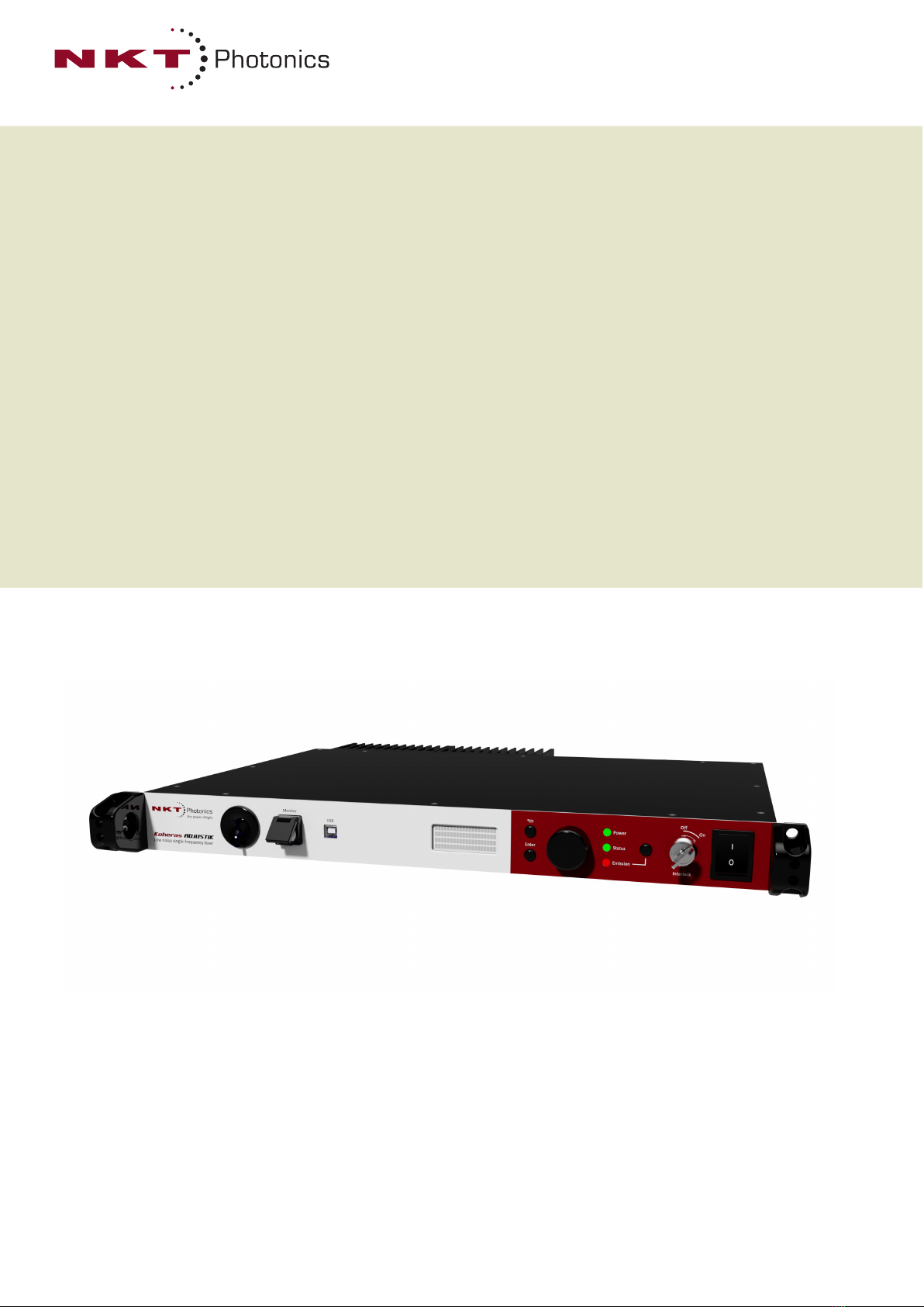
The Koheras ADJUSTIK is a single frequency distributed feedback (DFB) fiber laser
with passive vibration reduction. The laser system is housed within a rack mount
control chassis which includes a front panel operational interface. The laser’s optical
output is defined by an ultra-narrow line width in the Hertz range and exceptionally
low frequency and intensity noise. These characteristics make the laser suitable for
laser interferometry, coherent communication, microwave generation, spectroscopic,
and scientific applications.
Figure 1 ADJUSTIK front panel
A total of four variants of the laser are available with additional options that can
be specified. The variants are all designed with distributed feedback fiber laser
technology and center wavelengths can be specified from either 1535 to 1580
nanometers or 1030 to 1120 nanometers. All laser variants support a wide tuning
range of approximately 1 nm from the specified center wavelength.
Features and
Options
The laser series includes the following features and options:
• Thermal Tuning – can vary the wavelength through coarse thermal control of
the laser substrate.
• Piezo Tuning – provides fast wavelength modulation with finer control
• Standard or Polarization Maintaining (PM) fiber – PM fiber is available if the
application requires that the polarization is preserved.
• Wavelength modulation – the wavelength can be modulated using either an
external or internal signal.
• Power or Current modes – the lasers can operate in either constant power or
constant current mode.
• Adjustable output power (X15 variant only) – using an optional Variable
Optical Attenuator
• Emission features – multiple features that control emission availability from
the laser.

Module variants
20
Tuning
Tuning is accomplished by either manual thermal tuning or using an external
signal applied at the laser’s fast wavelength modulation input pins. A varying
external signal applied to the pins, modulates the output wavelength. Modulating
the output wavelength can obtain improved stabilization when compared with
the free-running wavelength specification.
Output fiber
The standard output of the laser utilizes either standard single mode fiber or
optional polarization-maintaining fiber to improve the linear characteristics.
Improved polarization linearity is usually required when the laser output is either
externally modulated or frequency converted.
Theory of operation
The ADJUSTIK is a fiber laser that uses a fiber Bragg grating cavity to produce an
output beam operating in single mode. The center wavelength of the laser is
configurable using either thermal substrate control or optional Piezo components.
Due to the special Bragg grating, the single mode operation is constantly maintained
and is stable over the entire operating frequency band of the laser.
Module variants
The Koheras ADJUSTIK is available in four variants. The variants are mainly
classified by their wavelength and output power. Table 1 describes the primary
technical differences between the variants.
Table 1 ADJUSTIK variant specifications
Center wavelength
The center wavelength of ADJUSTIK lasers is set to 1550.12 nm (ITU DWDM C-BAND
Channel 34) or 1064.00 nm. The lasers can also be specially ordered from the factory
with other center wavelengths ranging from 1535 to 1580 nm or 1030 to 1120 nm.
Output power
Depending on the module type, the output power varies between greater than 10 mW
and up to and including 40 mW. The output power is fixed for the lasers. however, a
Variable Optical Attenuator (VOA) can be specified with the laser to adjust the output
power over a large dynamic range.
Module Type Standard λ Other λs1
1. Fixed
Output Power Polarization
Maintaining
Fast Modula-
tion
X15 1550.12 1535 - 1580 nm 30 mW
(fixed)
2
2. Actual value depends on the factory calibration
Yes Yes
E15 1550.12 1535 - 1580 nm 40 mW (max.)3
3. Min. output ~30% of the maximum
Optional Yes
C15 1550.12 1535 - 1580 nm >10 mW (fixed)2Yes Yes
Y10 1064.00 1030 - 1120 nm >10 mW (fixed)2Yes Yes
2
Other manuals for Koheras ADJUSTIK
1
Table of contents
Popular Industrial Electrical manuals by other brands


ITRON
ITRON EquaScan FNet installation manual

Hitachi
Hitachi S10mini LQS070 user manual

Murata
Murata GRM0335C1H1R0CA01 Series Reference sheet

Power Electronics
Power Electronics SDRIVE DB Series Getting started manual

Murata
Murata GRM155R71C822KA01 Series Reference sheet

Murata
Murata GJM0335C1E9R0DB01 Series Reference sheet

Murata
Murata GRM0335C1H7R2BA01 Series Reference sheet

Eaton
Eaton MSFI-125A Instruction leaflet

Murata
Murata GRM0225C1E6R9WA03 Series Reference sheet

Murata
Murata GRT32DR60J226KE01 Series Reference sheet

Murata
Murata GJM0335C1HR47WB01 Series Reference sheet

Murata
Murata GRM2165C2A221JA01 Series Reference sheet