NLT DNS-33W User manual

10/30/2008
DNS-33W_8_12
DNS-33W Sports Camera
and the
SAT-2000 Transport
Sports Reference Guide
Software Version 2.24 FB DNS-33W
2.28 FB SAT-2000
October 2008

Page 2 of 24
DNS-33W/SAT-2000 Sports Reference Guide
This reference document helps you get started with your new DNS-33W camera or
Transport describing how to configure it specifically for sports acquisition. The document
includes procedures and the steps used to configure the Sports Recorder.
This reference guide includes 6 main sections:
•the basic steps to get started recording with the Camera or Recorder
•a description of the REMOTE ATTRIBUTE CONTROLLER (TETHER) options
•procedures to set up attributes before and during acquisition
•a description of the 12 setup procedures
•a reference to the 7 FieldPak tasks to perform
•a summary of practice and gameday setup procedures for quick reference
Page 3 of 24
Getting Started
One advantage of the Sports Recorder is the ability to assign attributes or metadata to
video during acquisition. Defining attributes you need streamlines editing and makes
locating clips faster and easier. The DNS-33W software has a set of screens that you use
to define these attributes. Instructions for setting attributes start below. Once you have
defined the attributes, refer to Section 6, of DNS-33W manual for specific instructions on
how to set up and perform basic camera functions. To get started recording, there are four
basic steps.
1. Set Up your Logging Device
Follow the steps below to get to the Recorder screen, which is the starting point for
assigning metadata attributes.
To define your attributes before recording:
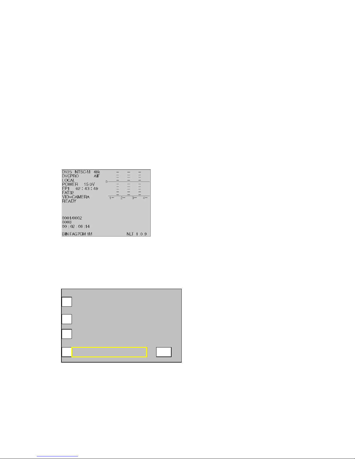
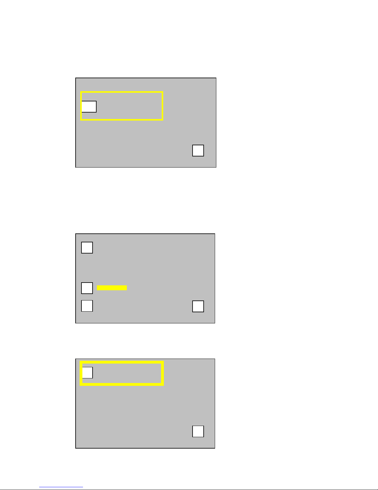
The Recorder (Status) Screen
a) Power on the device. The Recorder Screen, pictured above, displays.
b) Touch the Recorder Screen anywhere to display the Main Menu.
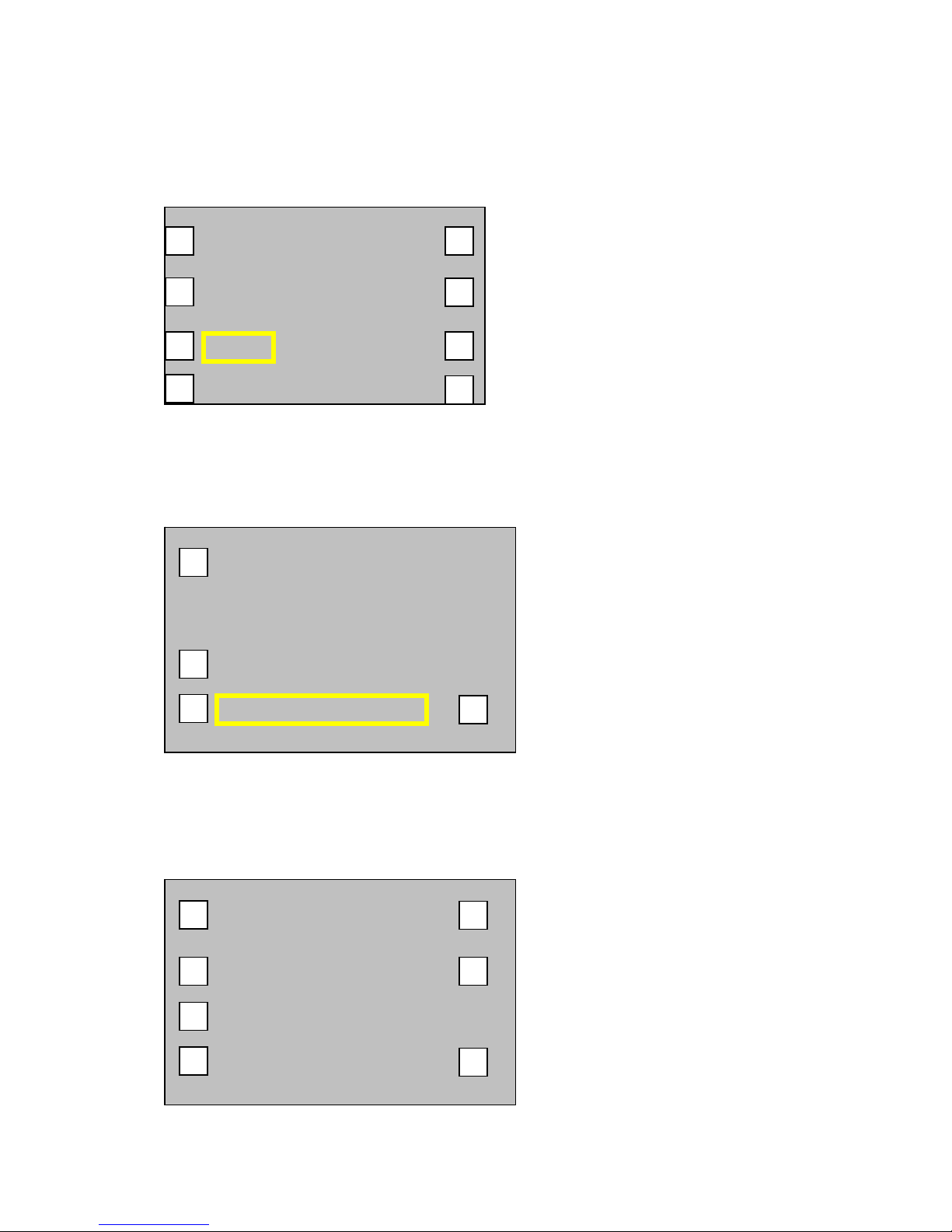
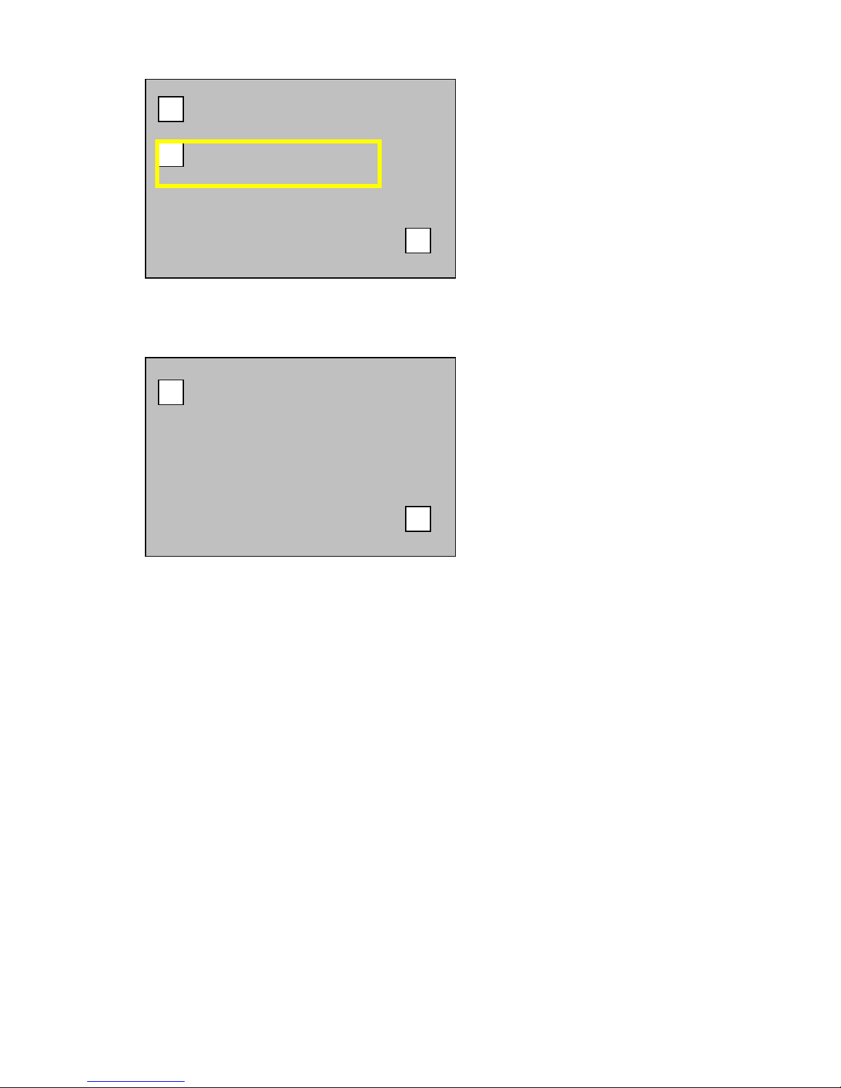
The Main Menu Screen
AUDIO/VIDEO
DISK OPERATIONS
RECORD/PLAYBACK
SYSTEM/SETUP
U
P
Set Up your Logging Device continued on next page
Page 4 of 24
c) From the Main Menu Screen, press the SYSTEM/SETUP button to display
the screen pictured below.
SYSTEM/SETUP Screen
INFO
TIME & DATE
SAT
OPERATIONS
TOUCH
SCREEN
INTERFACES
ENVIRON
UP
d) On the SYSTEM/SETUP Screen, press the SAT button. The SAT Screen
displays.
SAT Screen
CLIP ATTRIBUTES
CLIP NAME
SETUP
UP
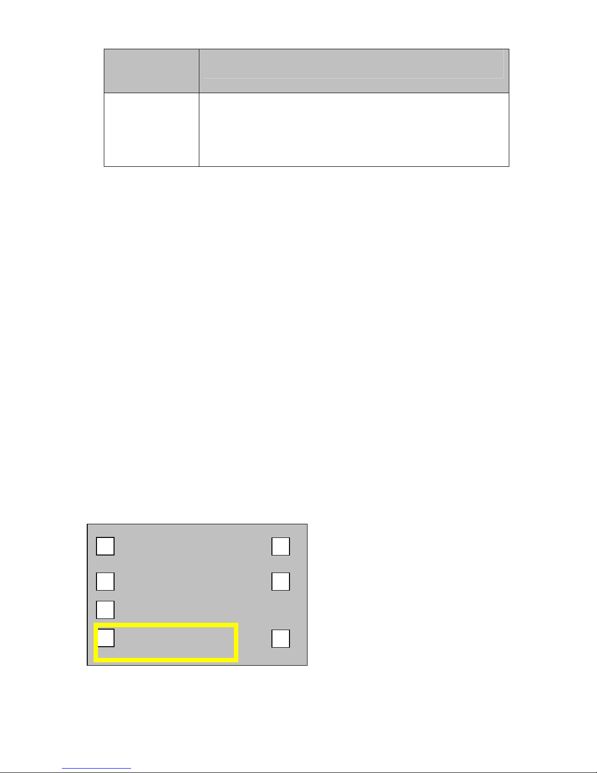
e) On the SAT Screen, press the SETUP button. This displays the SAT/SETUP
Screen. Now you are ready to store your attribute files into the Recorder.
SAT – SETUP Screen
ODK
ATTRS SET AT:
PAUSE
SET DEF ATTRS
TETHER
COMMANDO
CUSTOM
UP
Load Attr Files:
STARTUP:
ODK
Set Up your Logging Device continued on next page

Page 5 of 24
The top left button on the SAT/SETUP Screen is named TETHER. This defines the
type of logging device you are using. The TETHER button scrolls to offer three
selections described below, make your selection, then Power Off/On to enable the
setting to take effect (before using the TETHER device make sure it is attached to the
Recorder before power is turned on).
Button Use When
COMMANDO When the CoachComm-logging remote is attached, you will see
the STARTUP button display. The STARTUP button allows ODK
or CUSTOM attributes to be active at Power On.
DECK The Camera or Transport is connected to an RS422 deck
controlling remote with playback and record capabilities.
•
PALM A Palm Pilot is attached and used for logging (setting attributes).
The Palm Pilot software is available from NLT and is required to
be used in this configuration.
2. Define your Attributes and copy to a FieldPak
Refer to Understanding the Commando Attribute Options HOTLINK
a) Edit the file CUSTOM.ATR on your computer. Copy the file onto a FieldPak,
to the root level (to the top level when you open the FieldPak).
b) Edit the file ODK.ATR on your computer. Copy the file onto a FieldPak, to
the root level (to the top level when you open the FieldPak).
3. Load the Attribute Files into the Recorder
a) Insert the FieldPak with the defined attribute files into the recorder.
b) From the Main Menu screen go to the SYSTEM/SET/UP screen.
Select SAT, then SETUP.
c) Below the “Load ATTR Files”
(a) Select the CUSTOM button to read the file into the Recorder for later use.
(b) Select the ODK button to read the file into the Recorder for later use.
4. Power the Recorder or the Transport Off, then On
When you make your selections, you must turn the power off then back on again
before the setting takes effect (before using the TETHER device make sure it is
attached to the Recorder before Power On).

Page 6 of 24
Understanding the Commando Attribute Options
Commando ODK
1. Using the STARTUP button on the DNS33W SAT-SETUP Screen, select
ODK.
2. To change the text used for the ODK attributes, create/edit the txt file
ODK.ATR on your computer (Using NOTEPAD, WORDPAD or other TXT
editor), then copy the file onto a FieldPak, at the root level (the top level of the
FieldPak when you open it). This filename ODK.ATR should be all capitals.
3. Safely unmount the FieldPak from the computer and place it in the Camera or
Transport.
4. From the SETUP/SAT Screen, select the Load Attr Files, ODK button. The
camera reads the file, and associates the 8 ODK buttons to the 8 text fields.
An example file displays below.
ODK.ATR
#
# GAME DAY Attributes
ODK
1:01 OFF
2:02 DEF
3:03 KO
4:04 KR
5:05 PU
6:06 PR
7:07 FG
8:08 FGB
Note: Button 1 on the remote would log “01 OFF” as the single field attribute, in the
example above.

Page 7 of 24
Commando Custom
Selecting CUSTOM from the SETUP/SAT Screen will read the file CUSTOM.ATR
from the FieldPak and program the 64 attributes. There are 8 banks of 8 attributes in
each bank.
An example file displays below.
CUSTOM.ATR
# Set custom attributes
# Attribute names can only be 15 characters in length
# 64 attributes
1.0: ISO Drills
1.1: OL
1.2: DL
1.3: RB
1.4: LB
1.5: TE
1.6: DB
1.7: WO
1.8: Kickers
2.0: Interviews
2.1: Coach
3.0: Special Teams
3.1: KO
3.2: KR
8.0: Team Drills
8.1: Team Off
8.2: Team Def
8.3: 7 on 7
8.4: 9 on 7
8.5: pass rush
8.6: run block
8.7: 2 minute
8.8:Misc

Page 8 of 24
Setting Up Attributes During Acquisition
SAT-SETUP Screen
TETHER :
COMMANDO
ODK
ATTRS SET AT :
PAUSE
SET DEF ATTRS
STARTUP :
ODK
CUSTOM
up
Load Attr Files :
The ATTRS SET AT button defines when the attributes are assigned to the play during a
recording session. To make this function active the RECORD/RECORD-PAUSE mode
must be set to ON.
To Set Up Attributes During Recording
1. From the Main menu screen, select RECORD, then PAUSE-RECORD.
2. Press PAUSE-RECORD to ON.
3. From the SAT-SET UP screen, press the ATTRS SET AT button to toggle to your
choice of either PAUSE or EOP (End of Play).
ATTR SET AT
mode Use When
PAUSE During Recording the attributes that are selected will be
associated with the video just recorded, or the current sub-clip
(EG at the moment when recording is PAUSED). You need the
attributes selected before the recording is PAUSED to
associate attributes to the video just recorded. You can modify
attributes up until the moment the camera is placed into pause
mode by using the Attribute menu or by using your remote
logging device.
A MARK-IN and a MARK-OUT are assigned to the subclip’s
head and tail position of the video just recorded.
EOP During Recording the attributes that are selected will be
associated with the video just recorded, at the moment the EOP
button is pressed. You need the attributes selected before
pressing EOP to associate attributes to the video just recorded.
You can modify attributes up until the moment the EOP button
is pressed by using the Attribute menu or by using your remote
logging device.
Page 9 of 24
ATTR SET AT Use When
mode When using EOP mode several START-PAUSE events may
have occurred. When using SET ATTR AT EOP, these video
segments that were recorded are made into a single subclip, a
MARK-IN and a MARK-OUT are assigned to the subclip’s
head and tail position of the video just recorded.
Modifying Attributes While Using PAUSE
A subclip is made automatically after every PAUSE event and Attributes are assigned to
the subclip at the PAUSE event (Attributes can be modified until the PAUSE event). In
this mode each time a video segment is recorded (START then PAUSE) a new subclip is
made with marks and attributes. If during the game a false event was recorded which was
not a play then the extra play must be removed during POST editing. Noting the play
number will help identify the extra play to be later removed during editing.
Modifying Attributes While Using EOP
Pressing the EOP button while at a Pause assigns the active attributes to the video
recorded. Attributes can be modified until the EOP button is selected on the Commando
remote. This feature is useful for stringing video clips together as one video segment. For
example, if you want to have the scoreboard and play as one video clip not two, you
would set your camera to use EOP. The RET button (RETURN VIDEO REQUEST) on
the lens assembly also acts as the EOP button. In EOP mode, the RET button will mark
EOP.)
Setting Default Attributes
Selecting the SET DEF ATTRS button allows you to set the attributes to a predefined
set. The button lets you reset the football attributes to the initial, factory programmed
state. Use this option if the attribute strings loaded are not valid or if the camera is having
trouble with them (e.g., non-printable characters inserted into strings). Caution pressing
this button will erase any attributes previously loaded.
TETHER :
COMMANDO
ODK
ATTRS SET AT :
PAUSE
SET DEF ATTRS
CUSTOM
up
Load Attr Files :
STARTUP :
ODK

Page 10 of 24
Setting Attributes Using the Commando Remote
Each bank of attributes can be accessed on the COMMANDO by pressing the ODK and
EOP button at the same time (both buttons will begin to blink). This puts the remote in
CHANGE MODE: Select #1 - #8 for Custom attributes, or ODK for the game day
attributes.
•Selecting BANK (1 – 8): While in CHANGE MODE, once you press the bank
key, that button begins to blink. This is to show the user which bank is active.
Pressing 1 – 8 changes the attribute on the STATUS Screen of the camera to the
attributes of the selected BANK.
•Selecting ODK:This makes the ODK label active. Selecting the 8 offensive,
defensive, kicking attributes of the game will update the STATUS Screen.
•The EOP button: The EOP (end of play) button has special meaning and
characteristics. A clip is only created when the EOP button is pressed; no matter
how many times the record button is pressed. Once the EOP button is pressed,
the EOP button will stay lit until the camera returns to Record mode. This feature
allows the user to know if they have ended the play. The user can press the EOP
button while recording, and at the NEXT pause-record, the active attributes will
be assigned to the video clip and the EOP will remain on until recording begins
again.
If you do not have a Logging Tether, then use the Recorder screen. Refer to the “Logging
Using the Recorder screen” instructions below.
Setting Attributes using the Recorder screen
To log attributes using the LCD touch screen, follow these steps:
1. From the Main menu, go to the SYSTEM / SETUP, then SAT screen.
2. From the SETUP screen, press TETHER, until PALM is selected.
3. Power the Camera (OFF then ON)
4. Then from the Main menu, select SYSTEM / SETUP, then SAT and CLIP
ATTRIBUTES.
5. On the CLIP ATTRIBUTES screen, select Attribute(s).
6. Shoot Practice. Changing the attribute you need to change and continue shooting.
7. A good practice is to Press the STOP button after every set of drills. This makes a
new master clip.
Page 11 of 24
Setup Procedures
The general setup procedures are those tasks associated with setting up the DNS-33W or
SAT Portable Transport to record football games/events. Follow the steps provided to
complete each task. The following is a recommended list and brief description of each
task detailed in this guide.
Format a FieldPak: initialize the FieldPak you are using before recording.
Set a clip name: use the LCD panel to identify a clip.
Set unit identification: provide every recorder in your organization with a
unique identification number
Calibrate the video inputs: set up the system to accurately digitize the analog
signal
Save delay: set the maximum time the camera will wait in idle
mode before performing an Auto Save
Reset clip number: reset the master clip number or internal counter
Reset clip name and counter: change the master clip name in order to reset the name
and counter
Create and display a splash screen: follow the main menu to the screen that enables you
set and display a splash screen
USB KB to navigate and enter text: enter text and navigate with an attached USB
keyboard
LCD Touch panel’s function keys: use the Recorder LCD touch screen panel to perform
specific functions
Update the system: use a multi-step process to download and install the
most recent software for the DNS-33W or SAT
Transport
Backing up the system: follow a procedure to save configurations (including
metadata) to a FieldPak.
1. Format a FieldPak
Follow these steps to format each FieldPak before you record to it:
a) From the Main menu, select DISK OPERATIONS. Press the FMT button to
open the FORMAT DISK PAK Screen.
DISK OPERATIONS Screen
>FP1 RDY 40g 40g
MEDIA
TOOLS
DISK
STEETINGS
UP
UTL
EDIT ED
TOOLS
DISKS
BIN
MED
FMT
SET
Page 12 of 24
b) Hold SHIFT button down and press OK button. Open the keypad door to
access the SHIFT button. Caution Formating the FieldPak will erase any video
that was recorded to the FieldPak. This operation will take several seconds.
FORMAT DISK PAK Screen
2. Name the Clip Before You Record
To assign every clip a unique name:
a) From the Main menu, select SYSTEM / SETUP, then SAT. Press the CLIP
NAME button. The CLIP ATTRIBUTES/NAME Screen displays.
b) Press the CLIP NAME button and the NEXT NAME Screen displays. (At this
point, make sure that you are NOT in Record mode/NOT recording. The clip
name must be set before you record.)
CLIP ATTRBUTES
CLIP NAME
SETUP
up
FORMAT DISK PAK 1
CLR
OK
NEXT NAME:
up

Page 13 of 24
Name the Clip continued on next page
c) Press the NEXT NAME button then use the buttons on the Recorder screen to
enter the clip name. (Follow the directions in the ENTERING CLIP NAME
box below for directions on how to use the buttons to enter text.)
(a) Enter the name of your FieldPak on this screen using the buttons, and/or
USB keypad to enter text:
•Use > to advance 1 character, < to move back 1 character
•Use >>| to advance 10 characters, |<< to move back 10 characters
(b) Use the PLAY button to save displayed characters and automatically
advance to the next character.
NEXT NAME:
clr
SET NEXT CLIP NAME :
------------------------------------------
3. Set UNIT ID
It is important to set a unique Unit Identification (0-36) for each camera or recorder in
your organization. This needs to be done only once.
a) From the Main menu, go to DISK OPERATIONS, then select DISK
SETTINGS and the UNIT: X Screen.
b) Set a new ID for each camera. Media files will be named using this ID to
ensure unique filenames on the server.

Page 14 of 24
4. Calibrate VIDEO INPUTS
The Camera and Transport digitizes the input video during recording. The same
operation performed on an analog signal using a vector-scope must be performed on
the Transport to allow these devices to accurately digitize the video. Black must be set
to 0 IRE and white must be set to 100 IRE. You must adjust color saturation and hue
as well. These operations should be done periodically (either annually, after the
Camera/Transport maintenance, or if required to match input sources which may be
slightly out of calibration). The DNS33W video input can be calibrated using the
same process as the Transport but the switcher must be set to external.
Use the following procedure to calibrate the Transport. If the input source is not
properly calibrated, the Transport may capture degraded video. For the best results the
input source should be properly calibrated.
a) Use a calibrated input source such as a SMPTE test generator or camera.
Provide 100% SMPTE bars to the component and composite input. The SDI
input signal is a digital format and cannot be calibrated. Use the LCD to
navigate this path:
b) From the Main menu, go to AUDIO/VIDEO, then select VIDEO, and
CALIBRATE.
c) Prior to pressing Calibrate use the video input selector to select the component
(or composite) input to be calibrated.
d) The LCD will display the selected source. After confirming correct input
source and color bars, press: CALIBRATE VIDEO. The system will
automatically adjust the levels and offsets. The Transport will give a
calibration result such as “Excellent Calibration”.
5. Set SAVE DELAY
The Save Delay feature sets the maximum time the Camera/Transport will wait in idle
before it automatically saves your recorded clips. You only need to make this setting
this once. The default setting is five seconds.
To set the Save Delay:
a) From the Main menu, go to DISK OPERATIONS, then select DISK
SETTINGS and SAVE DELAY: 00:05
b) Use the keypad to change the number if you prefer a more frequent or longer
automatic save.
6. Reset CLIP NUMBER
This function resets the master clip number of the Camera or Transport. The clip
number is the internal counter, independent of the clip name counter.
To reset the Clip Number:
a) From the Main menu, go to DISK OPERATIONS, then select MEDIA
TOOLS and RESET CLIP NUMBER.
b) You can only reset the appended master clip number by changing the clip
name. To do so, follow the directions to reset clip name and counter below.

Page 15 of 24
7. Reset CLIPNAME and COUNTER
This function resets the master clip name and the number appended to the clip name.
The number that is appended to the clip name is automatically incremented for each
master clip created. The only way to reset this number is to change the master clip
name.
To change the master clip name:
a) From the Main menu, go to SYSTEM / SETUP, then select SAT and CLIP
NAME-NEXT NAME
b) Enter a new clip name using the buttons under the Recorder screen. The clip
number will begin with 0000.
8. Create and Display a Splash Screen
Creating a splash screen is another way to customize your DNS-33W Camera or
Transport.
To create a Splash screen:
a) From the Main menu, go to SYSTEM / SETUP, then select OPERATIONS
and DISPLAY SPLASH
b) Touch the screen to return to the previous screen.
9. Using a USB keyboard to navigate and enter text
You can use a USB keyboard to navigate and enter text in any text field on the
Camera or Transport. Before using the keyboard, the Transport must have the USB
functionality turned ON. (The USB interface is configured to the disabled position by
default.)
a) From the Main menu, go to SYSTEM / SETUP screen.
b) On the SYSTEM/SETUP screen, select Interfaces.
NETWORK and USB screen.
Using a USB Continued on next page
INFO
TIME &
DATE
SAT
OPERATIONS
INTERFACES
TOUCH
SCREEN
up
ENVIRON
NETWORK and USB Screen
Page 16 of 24
NETWORK
USB
up
c) Press the USB button to open the USB SUPPORT Screen.
USB SUPPORT:
ENABLE
up
d) When you press the USB SUPPORT button, you can toggle between
DISABLE and ENABLE. Toggle to select ENABLE.
e) Power the Camera Off, then ON again for the setting to take effect.
f) After restarting, attach a keyboard to the system. When attaching the keyboard,
the system will acknowledge the device by a displaying a message on the
Recorder screen or in the Viewfinder if you are using the Camera.
Using a USB Keyboard continued on next page

Page 17 of 24
Keyboard and Buttons
The table below indicates the keystrokes to use on the USB keyboard, the function that it
is equivalent to and the function it performs.
On the USB
Keyboard use Or use this
Equivalent Button on
the Recorder
To
CTRL + R RECORD Record
CTRL + S STOP Stop
PLAY Play if idle
CTRL + P
PAUSE-REC For SAT-2000, Pause if
recording
CTRL + E MARK EOP Identify the end-of-
play
CTRL + L RETROLOOP Engage Retroloop
CTRL + T TIMELAPSE Engage Timelapse
CTRL + F SHIFT + PAK1
or
SHIFT + PAK2
Switch to disk mode,
select FieldPak(P) 1
or 2
CTRL + D SHIFT + F8 •Go to Recorder
screen if in
submenu
•Toggle LCD screen
to Video/Recorder
screen
CTRL + V
CVBS, SDI, YRB Switch to default
video input source
Left arrow < Return to the frame
one step back
right arrow > Advance to the frame
one step forward
up arrow >>| Go to next clip/event
down arrow |<< Move to prior
clip/event
HOME |<< + <<< Move to first
clip/event
END >>| + >>> Return to last
clip/event
page up >>| + SHIFT Advance to next
bin/playlist
page down <<| + SHIFT Return to prior
bin/Playlist
ESC Clear / Exit edit mode

Page 18 of 24
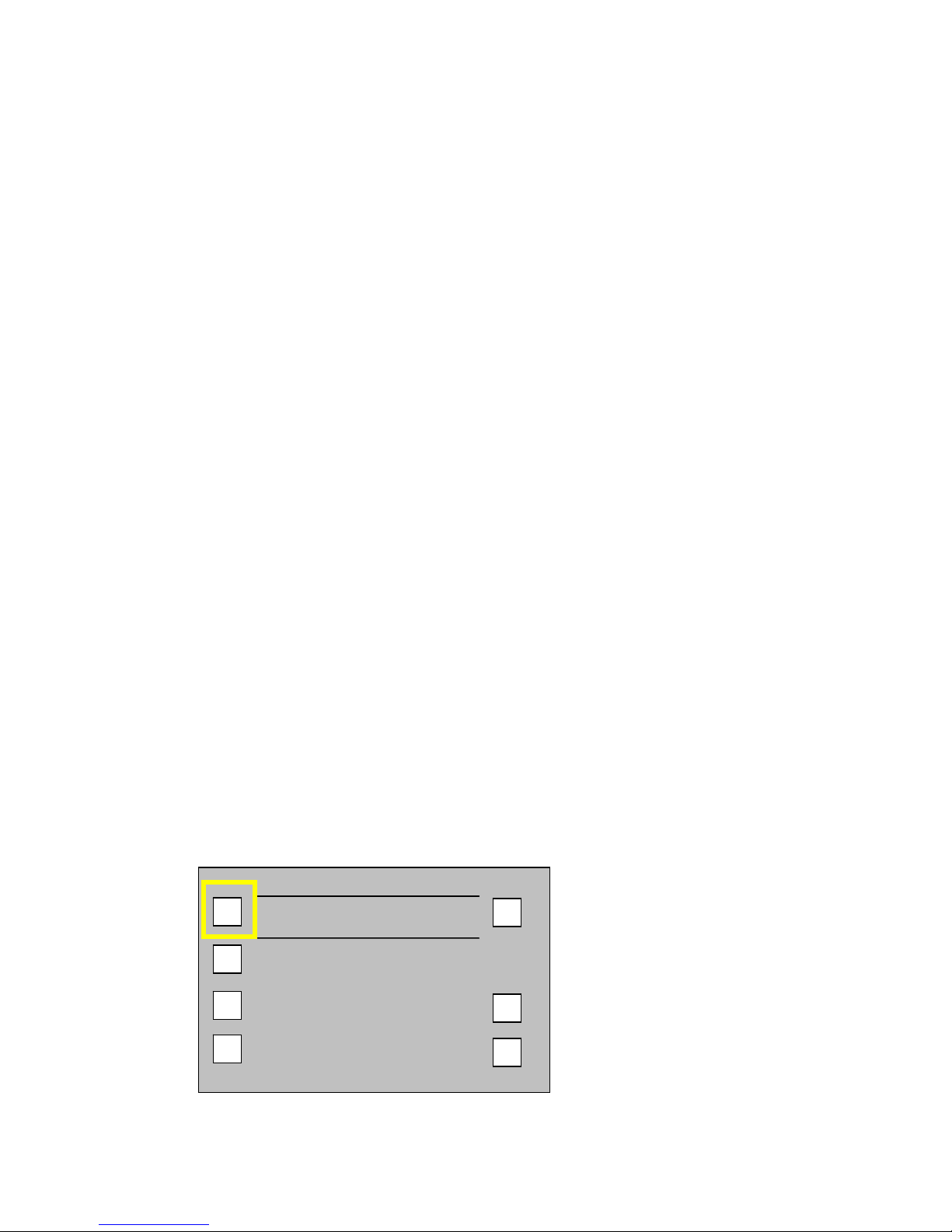
F Key Button Functions
The LCD Panel includes the function key buttons. The table below identifies each button
and describes it’s function..
F4
F3
F2
F1
F7
F6
F5
F8
Use This
Button To
F1
F2
F3
F4
F5
F6
F7
F8
10. Updating Your System
The time to update a system varies depending on what software components are
being reprogrammed. Updates usually take less than 10 minutes. If you experience
an update longer than this, please call support BEFORE you pull power. The LED
or buttons will flash in some sequence during the update to indicate progress. When
completed, the system may restart and the Recorder Screen will display. You will
note that the version number in the lower right corner will be the new version
number you installed.
Turn off the USB service, before you update your system’s computer.
To turn USB connections off:
•From the Main menu, go to the SYSTEM / SETUP screen.
•Select INTERFACES and USB. Then select USB SUPPORT: DISABLED
a) Gather the software update version you need from NL Technology. You can get
updates at www.nltek.com by FTP or CD-ROM, or you can call 978 686-1700.
b) Review the release/installation notes for any changes to this procedure.
c) Copy the new set of system files (specified in the release), to the top level of a
formatted FieldPak on your computer.

Page 19 of 24
d) Unmount the FieldPak and place it into the Camera or Transport. Before
beginning the update, make sure the Camera is being powered by AC or has a
full battery.
UPDATE
SYSTEM
BACKUP USER
PREFERENCES
ERRORS
DISPLAY
SPLASH
UP
UPDATE
SPLASH
e) To update, navigate to the SYSTEM OPERATIONS Screen by going to the
Main menu, and selecting OPERATIONS.
f) Press the UPDATE SYSTEM button. The START UPDATE Screen displays.
g) Hold the SHIFT button down while pressing the OK button to confirm the
update.
START UPDATE
CLR
OK
Note: Disruption of power during the system update may render the system
unusable.

Page 20 of 24
11. Backing Up Your System
The backup and restore function allows you to save the configuration (including
metadata) to a FieldPak or smart memory card. The file USERDATA.SAV can be
copied to a personal computer and restored to the Camera or Transport at any time.
a) From the Main menu, select OPERATIONS. Then select BACKUP USER
PREFERENCES.
b) Select the button which corresponds to the location where you want to save the
backup file.
SAVE
TO FP
SAVE
TO SM
RESTORE
FROM FP
RESTORE
FROM SM
UP
FILE: USERDATA.SAV
12. Restoring a Backup
To restore files, use the same process as you did when backing up your system but
in reverse. Place a previous USERDATA.SAV file on a FieldPak and navigate to
the OPERATIONS screen.
This manual suits for next models
1
Table of contents


