Nohken GW100NR User manual

TS02-100022
INSTRUCTION MANUAL
FOR
GUIDED PULSE LEVEL MEASUREMENT
MODEL: GW100
Revised 2020-10-28

- ADD 1 -
Read this manual carefully for safe usage.
・This manual applies to general purpose equipment. For equipment intended for
use in potentially explosive atmospheres, see applicable manuals.
・This manual contains important information on handling, inspection and
operation of the equipment indicated on the cover page. Before handling the
equipment, read this manual carefully.
・Instructions in documents submitted by Nohken or its representative have
higher priority than those in this manual.
・Keep this manual within easy access.
・Depending on environment, the equipment may not satisfy specifications
shown in this manual. Check the application conditions carefully beforehand.
・Please contact our sales office for any questions or comments about the
equipment or this manual. Sales offices are shown on the back of the manual.
Safety Symbols:
WARNING Means a potentially hazardous situation which,
if necessary precautions are not observed, can result
in death, serious injury and/or considerable material
damage.
CAUTION Means a hazardous situation which, if necessary
precautions are not observed, can result in minor or
moderate injury or damage to the device.
Means prohibited actions.
Means mandatory actions.

- ADD 2 -
WARNING
This equipment is NOT intended for use in potentially hazardous
atmospheres. Never use it where flammable gas or vapor may be
present. Failure to observe this may result in ignition of flammable
gas or vapor, causing disaster.
Do not alter or disassemble the equipment, unless you have been
instructed to do so by Nohken or its representative.
Failure to observe this may result in:
- malfunction of or damage to the equipment or connected devices;
- ignition;
- electric shock or user injury.
Turn off the equipment before wiring or inspection. Otherwise
leakage or short circuit may cause ignition or electric shock.
After wiring is complete, always check for its correctness. Wrong
wiring may cause:
- damage to or malfunction of the equipment or connected devices;
- ignition;
- electric shock or user injury.
Turn off the equipment immediately in case smoke, unusual smells
or sounds are noticed. Do not supply power until problems are
solved.
CAUTION
Handle the equipment with care. Do not drop, throw, or give
a strong shock to avoid damage.
Observe operation conditions specified in the manual. Use outside
the specified conditions may result in malfunction of or damage to
the equipment or connected devices, ignition, user injury, or
electric shock.
Perform operation tests before actual application to ensure
performance. Install back-up instruments based on different
technologies if failure of this equipment is expected to result in
a serious incident.
- ADD 3 -
CAUTION
Check carefully for chemical compatibility of materials of
construction before installation.
Use the flange, thread or somewhere close to the process
connection to handle the equipment. Do not use the housing to
avoid dropping the equipment, and resultant damage to the
equipment or user injury.
Equipment 50cm or longer:
Lay the equipment when not in use. Otherwise it may fall and
damage itself or things around it, and cause user injury.
Always ground the equipment. (Grounding resistance: 100Ωmax.)
Without grounding, electric shock may occur in case excessive
voltage is applied to the housing.
When connecting to inductive or lamp loads:
Ensure the maximum voltage/current ratings will not be exceeded
to avoid damage to the relay contacts.
Use lightening arrestors or surge absorbers to prevent:
- malfunction, damage, or ignition of the equipment and connected
instruments;
- electric shock or injury.

- ADD 4 -
INTRODUCTION
A) This manual applies to standard models. Please note that information in
this manual may not be applied to customized versions.
B) We are willing to help customers select a suitable model or provide
information about chemical compatibility of materials used, but the
customer is responsible for the decisions made.
C) We always welcome suggestions and comments about this manual.
Please contact our sales office when you have questions or comments.
D) Component replacement:
The equipment design is regularly reviewed and improved. The same
components therefore may not be available when replacement is required.
In such cases, different components or products may be supplied. Please
contact our sales office for detail.
E) The contents of this manual are subject to change without prior notice as
a result of improvement of the equipment.
WARRANTY & DISCLAIMER
A) Nohken warrants the equipment against defect in design or material, and
workmanship for a period of one (1) year from the date of original
shipment from Nohken’s factory.
B) Nohken will not assume liability for loss nor damage resulting from the
use of the equipment.
C) Nohken will not assume liability for damage resulting from:
C-a) not observing instructions in this manual;
C-b) installation, wiring, operation, maintenance, inspection, or storing in
a manner not outlined in this manual;
C-c) unauthorized alterations and repairs;
C-d) the use of or replacement with components not provided by Nohken;
C-e) devices or instrument other than those manufactured by Nohken;
C-f) the use not described in Chapter 1 Purpose of Use of the manual;
C-g) force majeure including, but not limited to, fire, earthquake, tsunami,
lightning strike, riot, commotion, war, armed conflict or terrorist
attack, radioactive pollution, act of God, governmental decisions or
actions, and compliance with laws and regulations.
THE PROVISIONS OF THIS SECTION DO NO LIMIT YOUR LEGAL RIGHTS.

Table of Contents
1.PURPOSE OF USE
····································· 1
2.DESCRIPTION
····································· 1
2.1 Product Overview ····································· 1
2.2 Principle of Operation ····································· 1
3.SPECIFICATIONS
····································· 2
3.1 Parts Name and Function ····································· 2
3.2 Model Numbering ····································· 3
3.3 Specifications ····································· 4
3.4 Outline Drawing ····································· 5
3.5 Probe length and Components ····································· 9
3.6 Optional Components ····································· 10
4.HANDLING NOTES
····································· 11
5.INSTALLATION
····································· 12
5.1 Tools for Mounting ····································· 12
5.2 Tools for Probe Trimming ····································· 13
5.3 Unpacking ····································· 14
5.4 Assembling Probe ····································· 15
5.4.1 Rod probe sensors (GW100□R□□) ···································· 15
5.4.2 Sensors with tubing with threaded connection(GW100NP□□) ················ 17
5.4.3 Sensors with tubing with gasket(GW100SP□□)······························ 19
5.5 Cutting Probe ····································· 20
5.5.1 Rod probe (GW100□R□□) ····································· 20
5.5.2 Wire probe (GW100□W□□) ····································· 21
5.6 Mounting Sensor ····································· 23
5.6.1 Location ····································· 23
5.6.2 Mounting ····································· 26
6.WIRING
····································· 27
6.1 Before Wiring ····································· 27
6.2 Wiring ····································· 27
6.3 Cable Inlet ····································· 29
6.4 Placing Cover ····································· 29
7.OPERATION
····································· 30
7.1 Before Operation ····································· 30
7.1.1 Key name and function ····································· 30
7.1.2 Modes and operation flow ····································· 31
7.1.3 Startup behavior ····································· 32
7.2 Commissioning ····································· 33
7.3 Quick Setting ····································· 33
7.3.1 Procedures ····································· 34
7.3.2 Canceling Quick Setting ····································· 37
7.4 Parameter Reference ····································· 38
7.4.1 Program mode parameter ····································· 38
7.4.2 Test mode parameter ····································· 43
7.5 Reference Drawing ····································· 44

7.6 Program Mode ····································· 45
7.6.1 Switching to Program Mode ····································· 45
7.6.2 Updating data ····································· 46
7.6.3 Canceling entry ····································· 47
7.6.4 Blanking ····································· 48
7.6.5 Fail-safe ····································· 50
7.6.6 Sensitivity ····································· 53
7.6.7 False echo suppression with material ····································· 55
7.6.8 False echo suppression without material ·································· 57
7.6.9 Reset ····································· 59
7.7 Test Mode ····································· 61
7.7.1 Switching to Test Mode ····································· 61
7.7.2 Exiting Test Mode ····································· 62
7.7.3 Simulation (mm, %) ····································· 63
7.7.4 Simulation (mA) ····································· 65
7.7.5 LCD test ····································· 67
8.MAINTENANCE AND INSPECTION
························· 68
8.1 Maintenance Procedure ····································· 68
8.2 When to Replace Components ····································· 68
9.STORING
····································· 69
9.1 Conditions ····································· 69
10.TROUBLESHOOTING
····································· 70
10.1 Error Code ····································· 70
10.2 Troubleshooting ····································· 71
11.APPENDIX
····································· 76
11.1 Glossary ····································· 76
11.2 Parameter List ····································· 77

- 1 -
1. PURPOSE OF USE
Guided Pulse Level Measurement GW is a sensor designed to continuously measure liquid level, and
provide output for alarms or to control pumps. Do not use the product for any other purpose.
2. DESCRIPTION
2.1 Product Overview
GW comprises of an electronics in a housing, process connection (threaded connection*or flange*)
and probe*. The probe is inserted into the tank and used to measure the distance to the material
level.
The probe assembly has no moving parts, so the material buildup and resultant adverse affection
to measurement are minimized. The user can cut off the end of the rod or wire type probe to a desired
length. The sensor is easy to program without needing a tester or other device to configure the
zero and span points.
2.2 Principle of Operation
The characteristic impedance of the probe changes when material surface reaches the probe.
The sensor electronics transmits high frequency signals that travel down on the probe. The signals
are reflected on the material surface, where the characteristic impedance changes, and then received
by the sensor electronics. The sensor electronics measures the time taken from transmission to
reception of the signals, and calculates the distance from the reference point to the material
surface. The distance is then converted to analog output of 4 to 20mA.
Fig. 2-1
* See
11.1 Glossary
.

- 2 -
3. SPECIFICATIONS
3.1 Parts Name and Function
GW100NR□□
Rod type
Threaded (G3/4)
Rod probe
GW100NW□□
Wire type
Threaded (G3/4)
Wire probe
GW100NP□□
Tubed type
Threaded (G1)
Tubed rod probe
GW100SP□□
Sanitary type
ISO 2.0 or equivalent
Tubed rod probe
① Cover
② Housing : protects the electronics.
③ Reference point : Point referenced to when deciding the measurement range. Location is model
dependent.
④ Probe : Component in rod or wire that is inserted in the tank and detects liquid
surface.
⑤ Lower blanking : Area close to the probe end where measurement is not possible or accuracy
low.
⑥ Probe length : Distance from the reference point to the probe end.
⑦ Upper blanking : Area close to the process connection where measurement is not possible or
accuracy low.
⑧ Cable inlet
⑨ Earth plate : Metal plate to stabilize operation. Required for non-metallic mounting
connection such as plastic vessel applications.
- 3 -
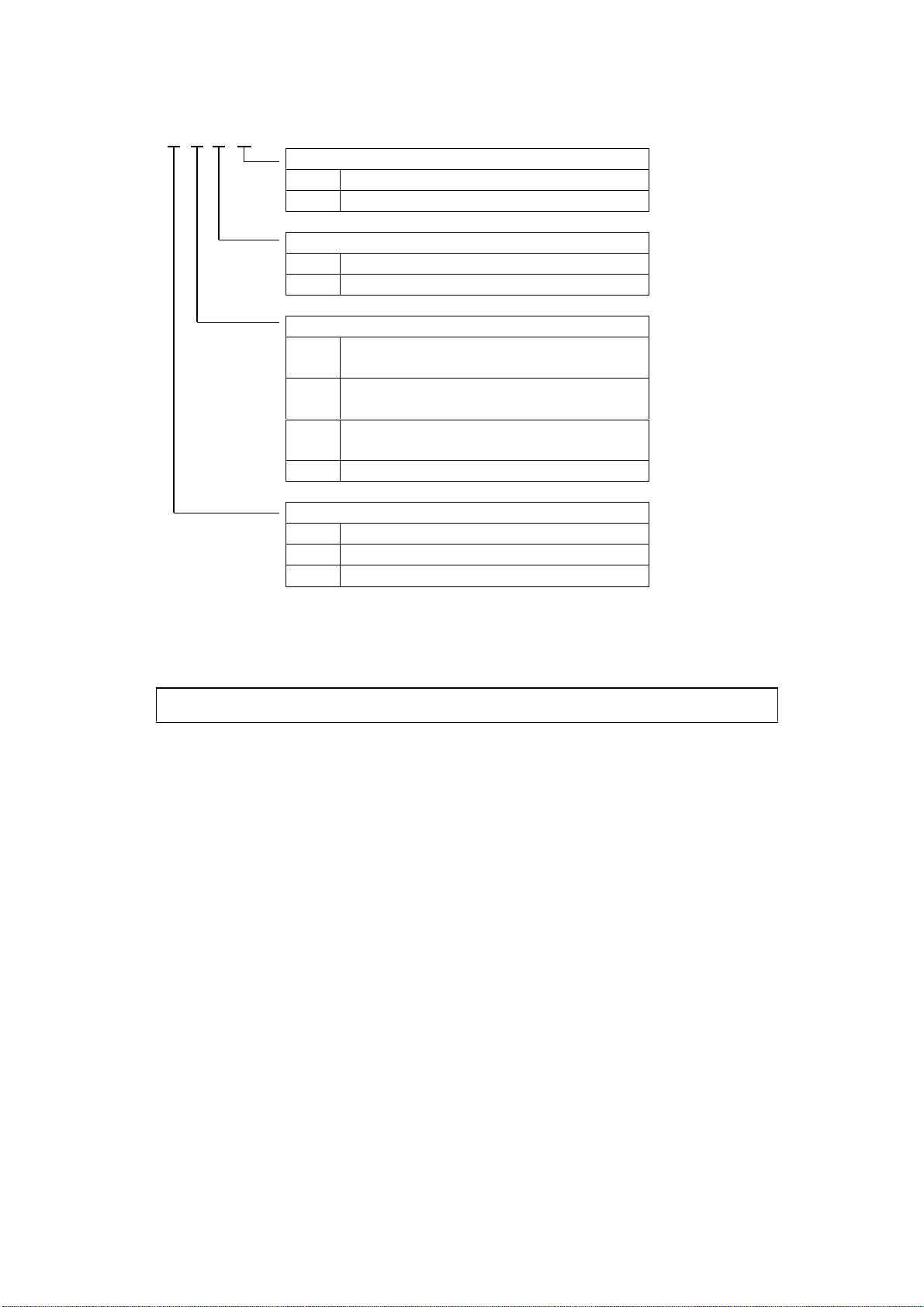
3.2 Model Numbering
GW100 □ □ □ □
Configuration
0*1 Without probe
1 With probe
Temperature
A Standard (100℃ max.)
T High temperature (150℃ max.)
Probe and material
R*2 Rod
316SS, PEEK, FKM
W*2 Wire
316SS, PEEK, FKM
PTubed rod
PFA, PTFE (316SS, PEEK, FKM)*3
Z Custom
Process connection
N Threaded
S Sanitary
Z Other connections
*1 Available only for Probe and material option “R”(rod).
*2 Not available for process connection option “S”(sanitary). Select “Z”here instead.
*3 Not wetted.
Rod and tubed rod probes are NOT factory assembled.
- 4 -
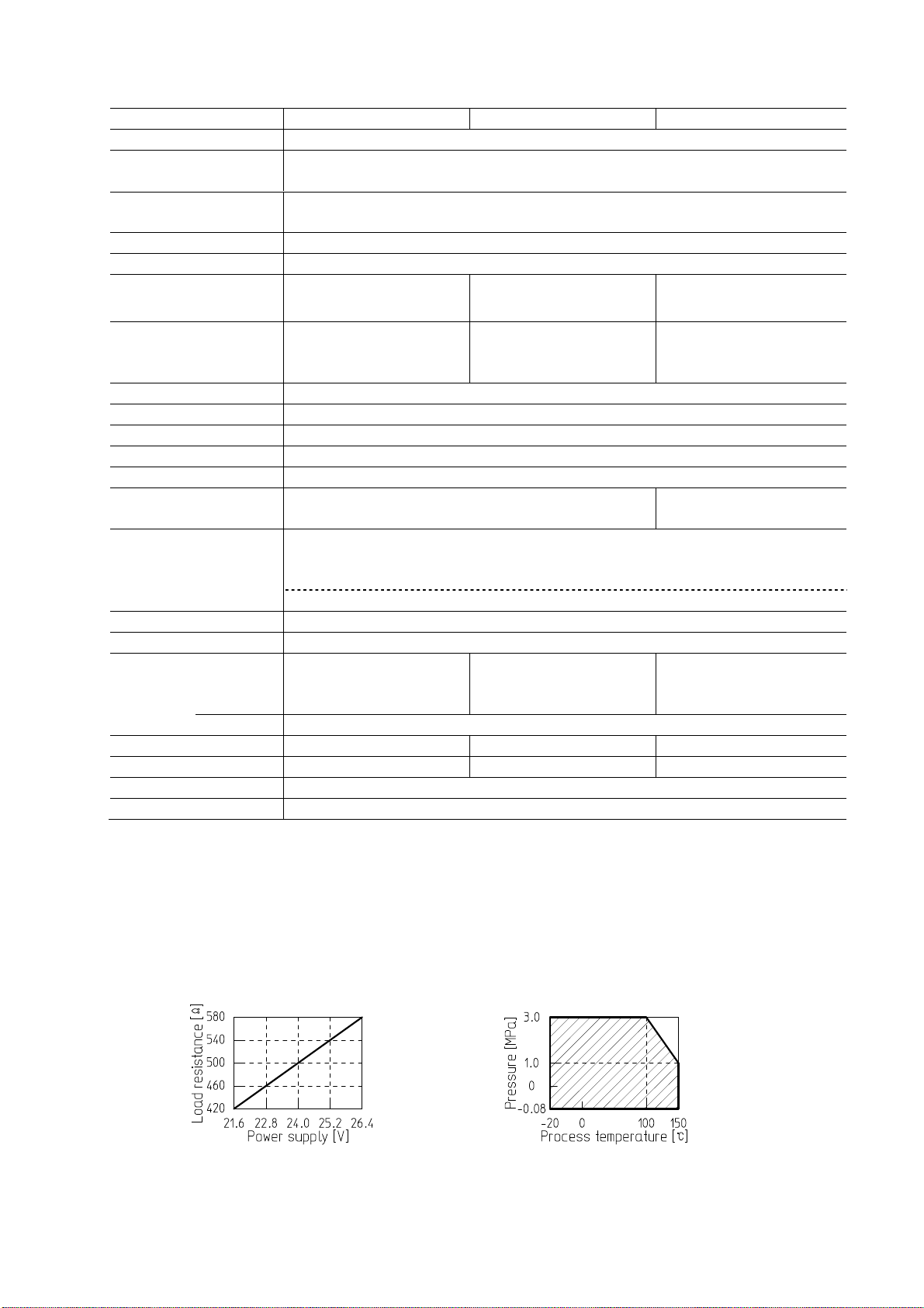
3.3 Specifications
Model GW100□R□□ GW100□W□□ GW100□P□□
Measured material Liquids
Accuracy*1, *2 up to 2000mm: ±10mm
remainder of range: ±0.5% of span
Temperature
characteristics ±0.02% of span/℃
Dielectric constant*εr≧ 1.8
Probe length*3 300 to 4000mm
Upper blanking*3
with water (εr= 80)*4 25mm min. 80mm min. 25mm min.
Lower blanking*3
with water (εr= 80) *4 10mm min. 165mm min.
(2% x Probe length +50)
mm min. or 60mm min.,
whichever is greater
Wiring 3 wire *5
Power supply 24V DC ±10%
Power consumption Approx. 2.0W
Output signal Analog output, 1 point, 4 to 20mA DC
Load resistance 500Ω max. at 24V DC (Fig.3-1)
Pressure (static) -0.08 to +3.0MPa
See figure 3-2 for high temperature version. 0 to +200kPa
Working temperature - Process
Standard version: -20 to +100℃ (no freezing)
High temperature version: -20 to +150℃ (no freezing)
- Ambient: -20 to +60℃ (no condensation)
Relative humidity 85% max.
Protection class Probe: IP68 / Housing: IP65
Material - process
316SS, PEEK, FKM 316SS, PEEK, FKM
PFA, PTFE
(not wetted - 316SS,
PEEK, FKM)
- housing Cast aluminum (ADC12), acrylic coated
Tensile load 4kN 4kN -
Lateral load 1.5Nm - 1.5Nm
Cable inlet G 3/4
Cable Shielded cable (recommended: CVV-S, 3x1.25mm2)
*1 Reference conditions
- Environmental: +25℃, 60%RH
- Application: metal tank (I.D. 84.1mm), 1200mm range, water (εr= approx. 80)
*2 ±15mm from reference point to 150mm
*3 See
3.4 Outline Drawing
.
*4 The lower the dielectric constant of the material, the longer the blanking will be.
- With Kerosene (εr= 1.8) upper blanking 200mm min., lower blanking 200mm min.
*5 See
6. Wiring
.
Fig.3-1: Load resistance Fig.3-2: Withstand pressure
(static, excluding process connection)
* See
11.1 GLOSSARY
.

- 5 -
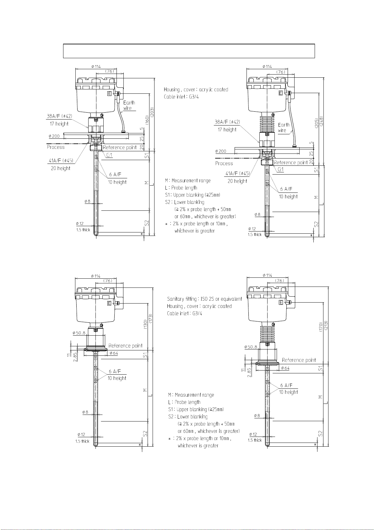
3.4 Outline Drawing
Rod and tubed rod probes are NOT factory assembled.
Fig.3-3: GW100NRA1 Fig.3-4: GW100NRT1
Fig.3-5: GW100NWA1 Fig.3-6: GW100NWT1

- 6 -
Fig.3-7: GW100NRA0 Fig.3-8: GW100NRT0
Fig.3-9: Component E Fig.3-10: Component L1M

- 7 -
<For non-metallic tank applications>
Tubing, gasket, earth plate, and probe are not factory assembled.
Fig.3-11: GW100NRA1 with Earth plate A Fig.3-12: GW100NRA1 with Earth plate B
Fig.3-13: Earth plate A (optional) Fig.3-14: Earth plate B (optional)
- 8 -
Tubing, gasket, earth plate, and probe are not factory assembled.
Fig.3-15: GW100NPA1 Fig.3-16: GW100NPT1
Fig.3-17: GW100SPA1 Fig.3-18: GW100SPT1

- 9 -
3.5 Probe length and Components
GW100NR□□ (threaded, rod probe)
Probe length (L) in mm Quantity End rod in mm
Component E Component L1M
300 to 1110 0 1 L - 80
1111 to 2090 1 1 L - 1060
2091 to 3070 2 1 L - 2040
3071 to 4000 3 1 L - 3020
GW100NP□□*(threaded, rod probe)
Probe length (L) in mm Quantity End rod in mm
Component E Component L1M
300 to 500 0 1 L - 53
501 to 1095 0 1 L x 0.98 - 43
1096 to 2095 1 1 L x 0.98 –1023
2096 to 3095 2 1 L x 0.98 –2003
3096 to 4000 3 1 L x 0.98 - 2983
* Earth plate thickness 5mm, gasket thickness 2mm
GW100SP□□ (sanitary, tubed rod probe)
Probe length (L) in mm Quantity End rod in mm
Component E Component L1M
300 to 500 0 1 L - 85
501 to 1128 0 1 L x 0.98 - 75
1129 to 2128 1 1 L x 0.98 –1055
2129 to 3128 2 1 L x 0.98 –2035
3129 to 4000 3 1 L x 0.98 - 3015

- 10 -
3.6 Optional Components
Item Description Remarks
Component E Extension rod (930mm, 316SS) x 1
Connection rod (50mm, 316SS) x 1
Screw (M4 x L5, 316LSS) x 2
980mm extension kit for rod versions
(GW100NR□□).
Component L1M End rod (1030mm, 316SS) x 1 Extends the probe length of rod
versions (GW100NR□□) to 1110mm.
Component L2M Component E x 1
Component L1M x 1
Extends the probe length of rod
versions (GW100NR□□) to 2090mm.
Component L3M Component E x 2
Component L1M x 1
Extends the probe length of rod
versions (GW100NR□□) to 3070mm.
Component L4M Component E x 3
Component L1M x 1
Extends the probe length of rod
versions (GW100NR□□) to 4050mm.
Gasket for G3/4 thread NBR gasket (Valqua, No.6500) x 1
(φ42mm, φ27mm, 2mm thick)
Standard accessory to GW100NR□□,
GW100NW□□, GW100NP□□ versions.
Gasket for G1 thread PTFE gasket (Valqua, No.7020) x 1
(φ49mm, φ34.5mm, 2mm thick)
Standard accessory to GW100NP□□
versions.
Earth plate A G3/4 threaded earth plate x 1
(φ200, 2mm thick, 304SS)
Comes with a gasket for G3/4 thread.
Earth plate B Earth plate for flange x 1
(φ200, 6mm thick, 304SS)
Specify the flange size at the time
of order.
Threaded tubing PFA tubing with G1 thread
ed
connection in PTFE x 1
Standard accessory to GW100NP□□
versions. Specify probe length at
the time of order.
Tubing with gasket PFA tubing with a PTFE
gasket fitted
to ISO 2.0S connections x 1
Standard accessory to GW100SP□□
versions. Specify probe length at
the time of order.
* Probe will be cut to the specified length at factory if requested.
- 11 -
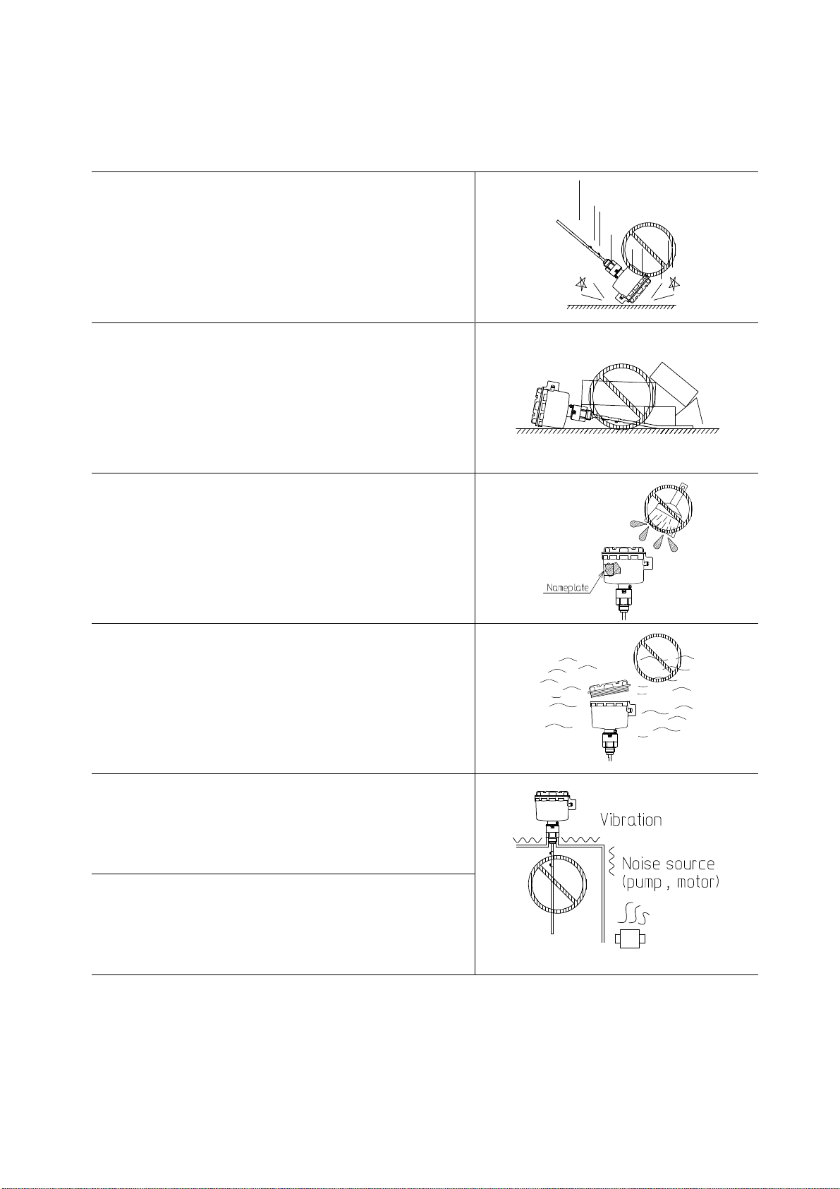
4. HANDLING NOTES
Observe instructions below when handling the sensor, or faulty operation or user injury may result.
Do not drop, throw, drag, or give a strong shock to the
sensor to avoid damage.
Do not place anything o
n the sensor to avoid deformation
or damage.
The nameplate contains maintenance and other important
information. Keep it legible when painting the sensor.
Avoid corrosive atmosphere (NH3, SO2, Cl2).
Such atmosphere may penetrate the housing and dam
age
internal components.
Avoid or protect against vibration.
Avoid strong magnetic fields such as proximity to a
large motor. Magnetic field may cause faulty operation.

- 12 -
5. INSTALLATION
WARNING
This product is not intended for use in hazardous areas*. Never use it
in areas where flammable or explosive gases or vapors may be present.
5.1 Tools for Mounting
Rod probes are not factory assembled. Assemble the probe before installation. Table 5-1 shows the
tools to be used for each model.
Table 5-1: Tools for mounting
Model
GW100□R□□
(rod)
GW100□P□1
(tubed, sanitary)
GW100□R□□
(rod)
GW100□P□1
(tubed, sanitary)
GW100N□□□
(threaded,
G3/4 or G1)
GW100NP□1
(threaded, G1)
Tool
Phillips screwdriver
x 1
Spanner (6mm A/F) x 2 Spanner (38mm A/F)
x 1
Spanner (41mm A/F)
x 2
Used on
Lock screws Rod Threaded connection Threaded tubing
Other tools than those mentioned above are necessary for flange fasteners, or the sanitary clamp.
Use suitable tools for your sensors.
* See
11.1 GLOSSARY
.
- 13 -
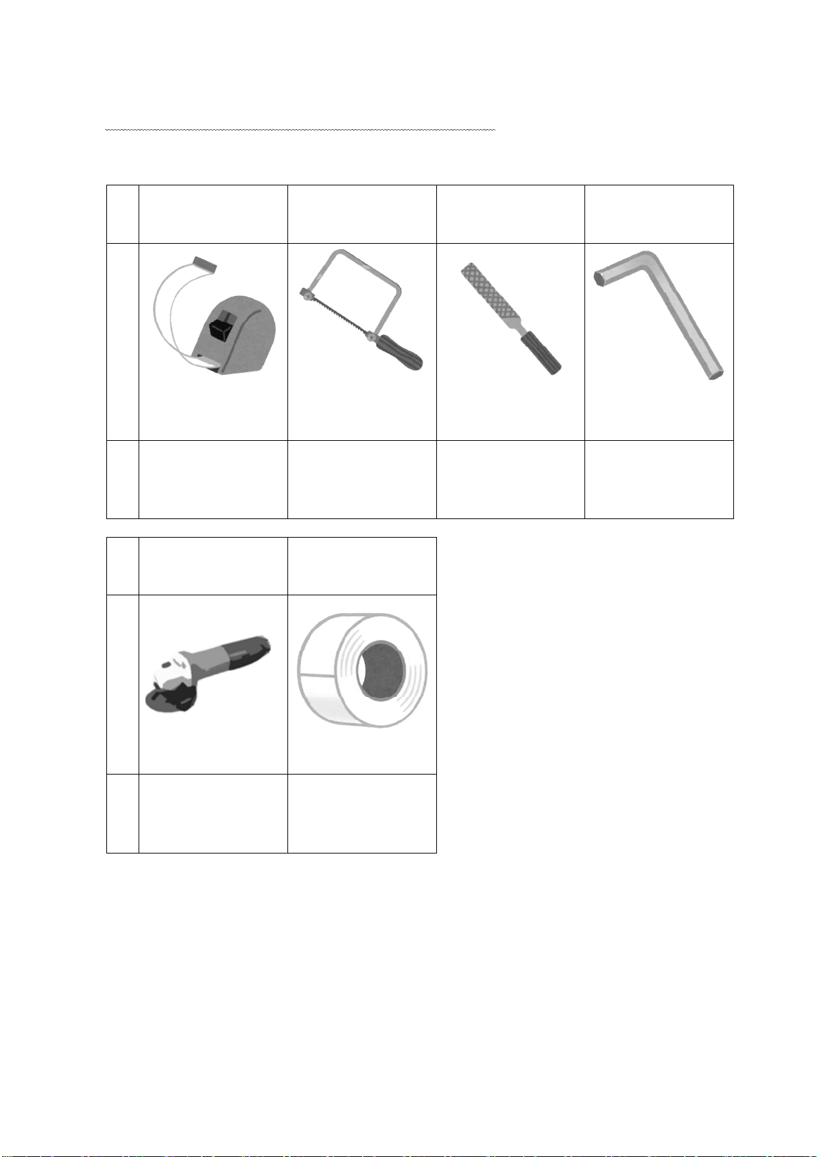
5.2 Tools for Probe Trimming
Rod or wire probes can be cut on site to a desired length. Table 5-2 shows the tools necessary
to cut the probe. See
5.5 Cutting Probe
on page 20 for how to cut the probe.
Table 5-2: Tools for cutting the probe
Model
All GW100□R□□
(rod)
GW100□R□□
(rod)
GW100□W□□
(wire)
Tool
Tape measure
x 1
Saw or grinder
x 1
Metal file or
sandpaper
Wrench (3mm A/F)
x 1
Used to
M
easure the probe
length.
Cut the rod. Remove burrs. T
ighten or loosen
weight screws.
Model
GW100□W□□
(wire)
GW100□W□□
(wire)
Tool
Grinder x 1 Plastic tape
Used to
Cut off the wire. Bind cut wire tip.
This manual suits for next models
3
Table of contents
Popular Measuring Instrument manuals by other brands


CS Instruments
CS Instruments FA 300-2 Ex instruction manual

HBM
HBM ME250 S6 operating manual

Spectrasensors
Spectrasensors SS2100 Hardware installation and maintenance manual

Apera Instruments
Apera Instruments PH60 instruction manual

Halma
Halma ALICAT SCIENTIFIC M operating manual

GW Instek
GW Instek GOM-804 user manual


