Noirot Intils HTi70 User manual

Made in
France
Manual ref.: 1898458
Edition no23.34
Installation and User manual
HTi70
High temperature, ultra modulating
Heat pump
HTi70 11 single-phase
Ref. 155020
HTi70 11 three-phase
Ref. 155060
HTi70 14 single-phase
Ref. 155030
HTi70 14 three-phase
Ref. 155070
The information contained in this document is non-contractual. The manufacturer reserves the right to modify any technical specifications and equipment of any appliances without prior notice

- MANUAL HTi70 11 14 KW HEAT PUMPS -
2

- MANUAL HTi70 11 14 KW HEAT PUMPS -3
TABLE OF CONTENTS
1SAFETY ............................................................. 4
2 PLEASE READ IMMEDIATLY ........................... 5
2.1 - Conservation of documents ............................................................5
2.2 - Symbols used........................................................................................5
2.3 - Abbreviations and acronyms...........................................................5
2.4 - Rating plate............................................................................................6
3 DELIVERY AND STORAGE............................. 7
3.1 - Delivery terms and conditions........................................................7
3.2 - Storage and transport........................................................................7
3.2.1 - General information ................................................................................................ 7
3.2.2 - Transporting with a forklift ..................................................................................7
3.2.3 - Transporting manually............................................................................................7
4 INTRODUCTION............................................. 8
4.1 - Operation................................................................................................8
4.2 - Accessories (included) .......................................................................8
4.3 - Accessories available to order.........................................................8
5 INSTALLATION................................................ 9
5.1 - Standard conguration .....................................................................9
5.2 - Placement.............................................................................................10
5.2.1 - Noise levels...............................................................................................................10
5.2.2 - Safe area.....................................................................................................................10
5.2.2.1 - Ground security area ............................................................................10
5.2.2.2 - Security area in front of a wall...........................................................11
5.2.3 - Accepted installation sites ..................................................................................11
5.2.4 - Prohibited installation sites ................................................................................11
5.3 - Setting up.............................................................................................12
5.4 - Condensate evacuation...................................................................12
5.5 - Hydraulic installation........................................................................13
5.5.1 - Hydraulic connections on the installation ....................................................13
5.5.2 - Hydraulic connection between Heat pump and pilot..............................14
5.5.2.1 - Hydraulic connections on the HTi 11 &14kW ..............................14
5.5.3 - Heat pump water inlet lter (supplied)..........................................................15
5.6 - Connecting to the power supply.................................................15
5.6.1 - General recommendations.................................................................................15
5.6.2 - Accessing the connection terminals ...............................................................16
5.6.3 - Recommendations for connecting the system to the power supply..16
5.6.4 - Connection to the power supply......................................................................16
5.6.4.1 - Single-phase connection ....................................................................16
5.6.4.2 - Three-phase connection .....................................................................17
5.6.5 - Communication bus cable between the heat pump and the pilot......18
6 MAINTENANCE AND TROUBLESHOOTING19
6.1 - General information .........................................................................19
6.2 - Maintenance on the hydraulic circuit.................................................19
6.3 - Maintenance of the Heat pump...................................................19
6.4 - Maintenance of the electrical components..........................................19
6.5 - Consulting the meters .....................................................................19
6.6 - Sensor data curve charts.................................................................20
6.6.1 - Waterinlet and outlet
Air intake sensor
Sensors installed on compressors 1 and 2 ..................................................................................20
6.7 - Modication.........................................................................................20
6.8 - Decommissioning..............................................................................20
6.8.1- Interim Decommissioning of Product..............................................................20
6.8.2- Final decommissioning of the product ...........................................................20
6.9 - Recycling and Disposal....................................................................20
6.9.1- Disposal of refrigerant ...........................................................................................20
7 LIST OF SPARE PARTS.................................. 22
8 WARRANTY ................................................... 24
8.1 - Warranty coverage ............................................................................24
8.2 - Limitations of warranty....................................................................24
8.2.1 - General information ..............................................................................................24
8.2.2 - Cases (not limited to) for exclusion from warranty ....................................24
8.2.2.1 - Heating circuit water ............................................................................24
8.2.2.2 - Handling....................................................................................................24
8.2.2.3 - Installation site........................................................................................24
8.2.2.4 - Electrical connections ..........................................................................24
8.2.2.5 - Hydraulic connections .........................................................................24
8.2.2.6 - Accessories...............................................................................................24
8.2.2.7 -Maintenance.............................................................................................24
APPENDIX .......................................................... 25
A1 - Technical specications....................................................................25
A1.1 - General characteristics..........................................................................................25
A1.2 - Performances............................................................................................................25
A2 - EU declaration .....................................................................................26
A3 - Frost protection ..................................................................................26
A4 - Treatment of the water in the heating circuit..........................26
A4.1 - Preparing the hydraulic circuit (rinsing) .........................................................26
A4.2 - Filling water..............................................................................................................26
A4.3 - Treatment of the heating circuit........................................................................26
A5 - Dimensions...........................................................................................27
A6 - Product technical information sheet ..........................................28
A6.1 - HTi70 11 kW single-phase Heat pump..............................................................28
A6.2 - HTi70 11 kW three-phase Heat pump ...............................................................29
A6.3 - HTi70 14 kW single-phase Heat pump..............................................................30
A6.4 - HTi70 14 kW three-phase Heat pump ...............................................................31
A7 - Internal wiring diagram ...................................................................32
A7.1 - HTi70 11 & 14 kW single-phase Heat pump....................................................32
A7.2 - HTi70 11 & 14 kW three-phase Heat pump .....................................................33
NOTES / MAINTENANCE ................................... 34

- MANUAL HTi70 11 14 KW HEAT PUMPS -
4
1-SAFETY
Danger resulting from improper qualications
• Any work carried out by an unqualied person
can result in damage to the installation or in
physical injury.
• Do not perform maintenance on this appliance
unless you are a qualied professional.
• If the appliance is malfunctioning or not
working, cut the electricicty supply to the
electrical components and seek advice from a
qualied professional.
Danger resulting from improper use
This appliance should not be used by anyone
(including children under the age of 8 years
old)with reduced physical, sensory or mental
capabilities, or by anyone with insufficient
experience or knowledge of the appliance; unless
they are being supervised by someone who is
responsible for their safety and in possession of
the operating instructions of the appliance, or if
they have been instructed in the proper use and
in the risks of operating the appliance.
Children must not play with the appliance.
Cleaning and maintenance of the appliance
must not be undertaken by children without
supervision.
Applicable areas of use
The appliance is intended for use an appliance
for the production of domestic hot water: it must
be connected to a heating installation, and while
complying with the instructions, connected to
the drinking water network.
The intended use of the appliance includes the
following points:
•Following the instructions for operating,
installing and maintaining this appliance and
all of its components.
• Ensuring the compliance of the appliance to all
inspection and maintenance conditions which
are listed in this manual.
Danger of death by electrocution
• Touching live electrical wires can cause severe
bodily injury, and lead to death by electrocution.
All installation and maintenance work must be
carried out with the appliance switched o and
by a qualied professional. Before carrying out
any work on the appliance:
-Cut-o the electricity supply.
- Ensure that there is no possibility of the power
supply becoming active again.
-Wait at least 5 minutes for the capacitors to
lose their charge.
• Do not get water on any of the control or
electrical components. Always disconnect the
appliance from the electricity supply before
carrying out work on any of the electrical
components.
Danger of death if the pressure relief valves
are missing or defective
A defective pressure relief valve may prove
dangerous and could lead to burns or other
injuries by, for example, the pipes bursting.
The information presented in this document does
not contain all of the schematic diagrams needed
for a professional installation of the pressure relief
valves.
• Install the necessary pressure relief valves on
the circuit.
• Inform the user concerning the function and
the placement of the pressure relief valves.
• Respect all applicable national and international
regulations, standards and decrees.
Risk of material damage
The heat pump can only work when lled with
water. Never switch on the appliance if it is not
completely lled with water and purged of air.
Rules and regulations (decrees, standards,
laws)
Once the appliance is installed and switched
on, all decrees, directives, technical rules, safety
measures and standards, must be respected in
their current version in eect.
The electrical supply must conform to all
applicable regulations in the country of
installation, as well as the NFC 15-100 standard.
• Amethod ofdisconnection ensuring acomplete
cut-o must be installed in the xed piping to
conform to installation regulations (do not use
a movable outlet).
•Protect the appliance with a 2-pole circuit
breaker with a minimum contact opening of
3mm and must be grounded.
• The devices for electrical cut-o must remain
accessible.
• Water may drain from the discharge pipe of
the pressure limiting device. This pipe should
be kept open to open air.
• The pressure relief valve is mounted on the
condenser. Ensure that the drainage is properly
oriented to prevent water from leaking onto the
electrical components.
Maintenance - Troubleshooting
Maintenance and cleaning of the pilot must be
carried out at least once a year by a qualied
professional.

- MANUAL HTi70 11 14 KW HEAT PUMPS -5
•The appliance should be cleaned carefully
so as not to damage its electronics from the
outside. The use of a high pressure cleaner is
PROHIBITED.
• Any intervention on the refrigeration circuit
must be made by a qualified person who
holds a Category 1 certicate of tness.
Refrigerant R290, contained in the heat pump
circuit, does not pose an environmental hazard
but is ammable.
→Refrigerant R290 is odorless.
→Do not damage the refrigeration circuit
tubes,
→Do not handle ame or other ammable
sources inside the device,
→In the event of a leakage of the refrigerant,
unplug the plug, ventilate the room and
contact the customer service,
→Do not pierce or burn the appliance: the
recovery of the uid is mandatory in case
of intervention on the refrigeration circuit.
REFRIGERANT CIRCUIT
2 -PLEASE READ
IMMEDIATLY
This technical installation manual forms part of the appliance which
it refers to. In order for the warranty to be valid, the instructions must
be read prior to using the appliance.
The safety advice and instructions provided in this manual must be
strictly respected.
Our society is not liable for any damages caused from not following
the instructions provided, or improper handling, installation or use.
This technical installation manual can be modied without prior
notice.
This manual must be safeguarded and passed on to successive users
for future reference.
It will be considered as evidence in case of litigation.
2.1 - Conservation of documents
DHW.......Domestic Hot Water
DCW .......Domestic Cold Water
T°..............Temperature
HP............Heat pump
2.3 - Abbreviations and acronyms
Type and refrigerant charge.
PS : Max high service pressure
Indicates warnings and important recommendations.
2.2 - Symbols used
Contains regulated substances, do not throw in the
garbage. If disposing, please respect all regulations
pertaining to the recovery of electric and electronic
equipment.
Heat power output produced.
Pnom : nominal
Max current protection (A)
Caution : contains a ammable refrigerant uid.
Please make sure to respect the installation and
handling precautions.
Consult the installation manual before any intervention
on the product, before handling, installation, use , and
maintenance.

- MANUAL HTi70 11 14 KW HEAT PUMPS -
6
2.4 - Rating plate
1898305
Ser.n° : 155020-232300000
Hermétiquement scellé / Hermetically sealed
Made In France
Réf :
155020
HTi 11 mono
70
Pompe à chaleur
AUER
Rue de la République
80210 Feuquières en Vimeu
*Selon EN14511 / According to EN14511
1898305
*Selon EN14511 / According to EN14511
R290 (groupe 1) : 0,900kg
PS : 3,1MPa (31 bar)
Ts min : -20°C
Ts max : +40°C
230V mono ~ 50/60Hz
Imax : 30A - Pmax : - kW
Pnom* : 8,95kW
COP* : 4,85 (A7W35)
IPX4
P : 0,3MPa
(3 bar)
PED cat. 1
136 kg
Manufacturer’s identity
Appliance identity
Serial number of the appliance
Appliance type
Certication agency
intuis reference
of the appliance
Rating plate reference
appliance weight
CE marking
Appliance electric data
PED’s category
According to 2014/68/EU
Protection rating
Reference of
the appliance
Year of
manufacture
2023
Week of
manufacture
Appliance
number in the
series
155020 - 23 23 00000
Serial number of the appliance
Maximum hydraulic system
pressure
P : 0,3MPa
(3 bar)
Pnom* : 8,95kW
COP* : 4,85 (A7W35)
Nomimal performances
According to EN 14511
Description :
Refrigerant type/quantity
R290 (groupe 1) : 0,900kg
PS : 3,1MPa (31 bar)
Ts min : -20°C
Ts max : +40°C
H
L
Outside temperature limits
operating
Maximal pressure of the refrigerant
circuit

- MANUAL HTi70 11 14 KW HEAT PUMPS -7
3.2 - Storage and transport
Admissible storage and transport temperatures of the appliance are
between -20°C and +60°C.
The appliance must be stored in a room that does not contain
sources of ignition that are continuously operating (for example,
bare res, gas appliance or electric radiator in operation).
3.2.1 - General information
The appliances must be stored and transported packaged and
on their wooden pallets, in a vertical position, and completely
empty of water.
3.2.2 - Transporting with a forklift
When transporting with a forklift truck, the Heat Pump must be on
its wooden pallet.
When moving the Heat Pump do not lower or raise the unit suddenly
as the Heat Pump can easily lose it equilibrium. The Heat Pump should
be suitably secured to prevent it from tipping.
3 - DELIVERY AND STORAGE
3.1 - Delivery terms and conditions
In general, the material is transported at the recipient’s own risk.
It is important to verify that all of the elements have been received
and that no damage has been sustained during transport upon
receipt of the appliance and before beginning the installation
procedures.
1. Heat pump
2. Hydraulic connection kit
(inside the heat pump)
3. Hydraulic pilot
3.2.3 - Transporting manually
The Heat pump can be transported manually.
The Heat pump must always be transported in a horizontal position,
including during installation.
Do not handlethe unit by its hydraulic connections.
It’s possible to transport the appliance with straps (not supplied)
The appliance can be moved using straps (not provided) through
the four slots at the base. If necessary, carry paratransit equipment
to avoid any risk of incident.
Do not incline more than 30°
Maintain a protective covering on the nned
heat exchanger during handling.
* Straps not supplied.
Installation procedures must be carried out by a qualied professional,
so as to prevent any risks of bodily harm and/or material damage.

- MANUAL HTi70 11 14 KW HEAT PUMPS -
8
4 - INTRODUCTION
1. Compressor
2. Pressure reducer
3. Evaporator
4. Condenser
5. Ventilator
6. Heating inlet / outlet
7. Condensates drainage
Note:
The Heat Pump is exclusively designed for heating purposes.
It cannot be used for cooling.
The manufacturer cannot be held responsible for any other usage
of the appliance.
4.1 - Operation
The Heat pump is a closed and pressurised system in which the
refrigerant serves as the medium for transferring energy.
A safety pressure switch is used on the refrigeration circuit, it is
located on the high pressure part of the circuit at the output of the
compressors. It is a dry contact that when the pressure becomes
too high (>31 bar) opens. Once opened, it cuts the power to the
compressors, independently of the electronics and thus protects
all circuit components.
The evaporator dis a cooling exchanger which draws calories from
the air. The humidity in the air condenses on contact with the cold
surface, and forms condensation which must be drained regularly
during operation of the Heat pump (evacuation in h).
The condenser eis a plated heat exchanger which allows to transfer
the heat towards the heating water of the installation g.
The operating range of the Heat pump ranges from an air
temperature of -20°C to 40°C.
It is FORBIDDEN:
•tooperate the Heatpumpusing airintake
containing solvents or explosive materials.
• to use air intake containing grease, dust, or
aerosol particles.
• to connect vented exhaust hoods to the
appliance.
Use of the appliances are FORBIDDEN if
the installation is not lled with water.
External defrost kit (Réf. 754101)
to keep the external condensate evacuation duct from
freezing.
4.3 - Accessories available to order
2-core sheathed cable (Ref. 753102)
linking the Heat Pump and the Pilot (lg 20m)
20m length for connection instead of the
10m length delivered as standard.
Adjustable raiser kit for heat pump (Ref. 754600)
allows raise of the heat pump and catch up with ground levels.
4.2 - Accessories (included)
The components described below are delivered with the Heat
Pump:
2-core sheathed cable linking the
Heat Pump and the Pilot (lg 10m)
HTi70 11 & 14 Hydraulic Fitting (Ref. 751019)
(included a 1’’lter valve, a safety valve assembly 1’’1/4, 2 vannes
d’isolement 1"1/4, 1 purgeur manuel, a hydraulic connection
[reduction F3/4 M1’’ + nipple MM 1’’])
HTi70 accessory kit
Set of four mounting feet.

- MANUAL HTi70 11 14 KW HEAT PUMPS -9
5.1 - Standard conguration
5 - INSTALLATION
• The Heat pump must be installed outside exclusively.
• Avoid any obstruction of the airow of the ventilator.
Ensure that there is nothing blocking the exchanger’s air circulation. Ensure that the Heat pump is placed so that
it is sheltered from dominant winds.
It is prohibited to install the Heat pump:
• In a non-ventilated room.
• Near sources of excessive heat, combustible
materials, or near ventilation points of adjacent
buildings.
• Near a kitchen or workshop exhaust ducts; this
can result in a mixture of oil and air settling onto
the heat exchanger ns which could hamper its
performance.
• In an area with ammable gaz, acidic substances,
or alkalines which could cause irreversible
damage to the copper-aluminium heat
exchanger.
PROHIBITED INSTALLATION
• Avoid installing the Heat pump in a
location subject to noise reverberation such
as near windows or near the corners of buildings.
• As the condensates draining trough slopes
downward, the Heat pump must be installed on a
level base.
• The Heat pump must be easily accessible so as to
facilitate access for inspections and maintenance.
IMPORTANT INSTALLATION RULES
Pilot
HTi70
heat pump
2 electrical supplies
230V single phase
hydraulic
connection
communication
cable
2-core sheathed

- MANUAL HTi70 11 14 KW HEAT PUMPS -
10
5.2 - Placement
The Heat Pump is designed to be installed outdoors exclusively, while respecting a minimum of free space around the appliance in an area free
from excessive levels of dust. It should never be placed in an enclosed space.
The Heat Pump is designed to operate in rainy weather conditions, although it can be installed under a well-ventilated shelter (Withan opening
large enough to allow sucient air ow for intake and exhaust).
Regarding the fan, the free space from any obstacles must be at least 2m.
≥ 50cm
≥ 1m
≥ 1m
≥ 50cm ≥ 50cm
≥ 2m
Placed on the
ground or on a
terrace
(empty area) Placed against a wall
+3dB (A) Placed in a yard
+9dB (A)
Placed in a corner
+6dB (A)
5.2.1 - Noise levels
The Heat Pump is equipped with a large diameter fan so as to allow for an appropriate air ow rate. This ow rate can rise up to 9.000 m3/h. The
fan speed is adjustable to limit the noise level.
Depending on the installation conditions, the noise levels may be dierent, in particular if the walls closest to the Heat Pump cause a reverberation
and amplication of noise.
The diagrams below show dierent installation examples for dierent placements.
5.2.2 - Safe area
The heat pump contains a ammable refrigerant. In case of leak, the refrigerant could accumulate near the ground (higher density than air). or
spread through openings in the building. In order to limit the risk of a toxic, suocating, explosive or dangerous atmosphere, a safety perimeter
must be established around the machine.This perimeter must not include a window, door, or any openings towards the interior of the building.
5.2.2.1 - Ground security area
Observe this area if the heat pump is in free eld.
A
A
A
A

- MANUAL HTi70 11 14 KW HEAT PUMPS -11
5.2.2.2 - Security area in front of a wall
This area must be respected if the heat pump is against a wall and close to the opening of a building.
Distances from the security perimeter (mm)
HTi70 11kW HTi70 14kW
A 1000 1000
B 1300 1300
C 1600 1600
D 500 500
D
A
C
B
AA
C
B
AA
5.2.4 - Prohibited installation sites
Underneath a
window
Neighbouring
home
5.2.3 - Accepted installation sites
Oset from all
windows
The noise prevention screen must be made of insulated materials.
Neighbouring
home
Neighbouring
home
Neighbouring
home
- MANUAL HTi70 11 14 KW HEAT PUMPS -
12
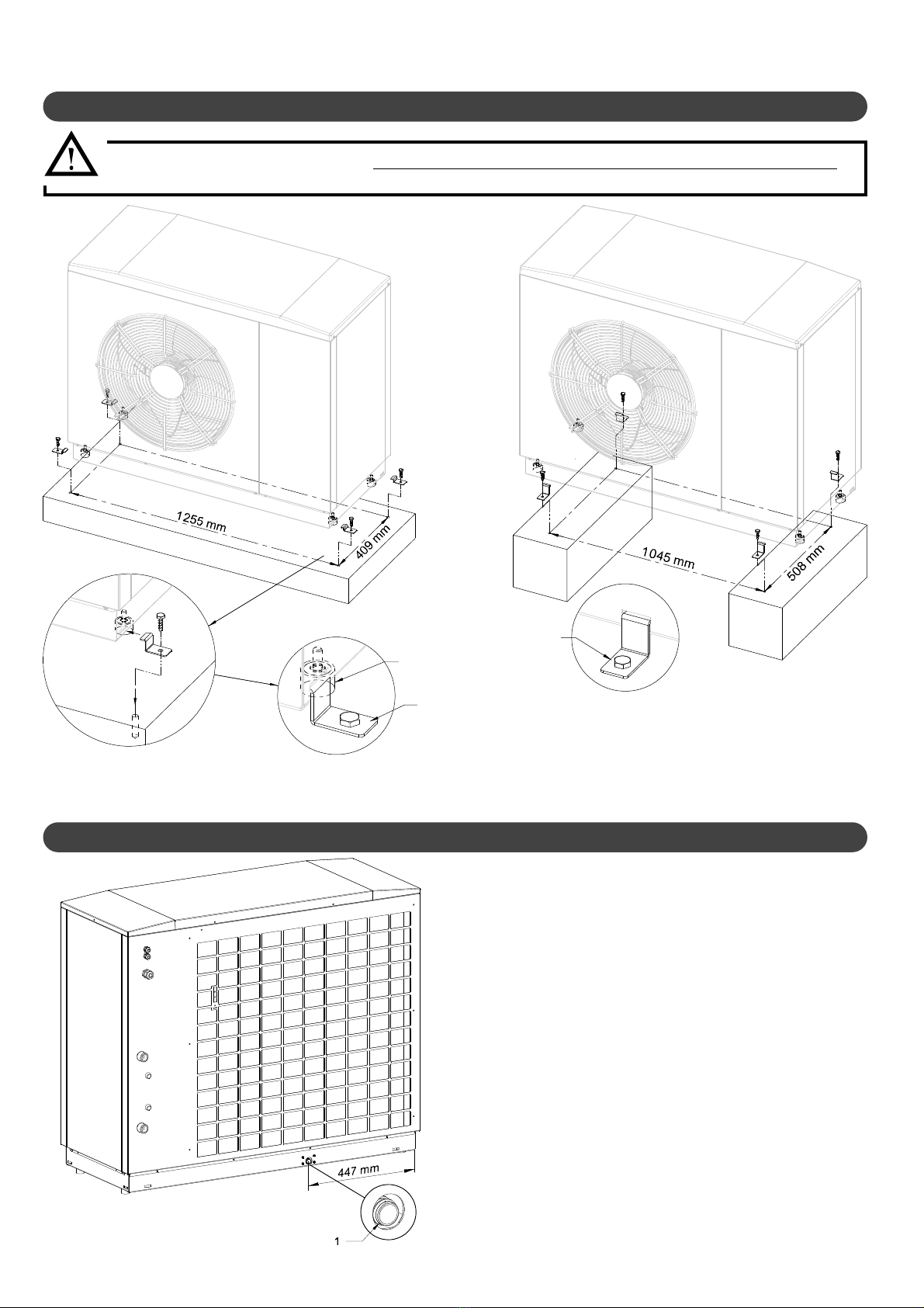
5.4 - Condensate evacuation
When the appliance is operating in frost protection mode, the
condensed water must be drained o. In order for the condensates
to drain properly, the drainage trough and hole 1must be clean and
free of all debris (leaves, grass, etc...).
During cold weather, ice may form on the evaporator.The heat pump
has an automatic defrosting system to eliminate this phenomenon.
Do not use tools to remove the glass as this could damage the
evaporator.
The condensates can be connected to the drain with the optional
external defrost kit (Ref. 754101). It’s made up of a reinforced PVC
pipe and a heating cord allowing drainage in freezing weather.
It’s also possible to let the condensates ow freely at the back of
the heat pump. In this case, it’s necessary to provide in the ground
a device allowing a drainage of water in depth.
5.3 - Setting up
The Heat pump must be installed on a hard and stable base, which is suciently raised from ground level to
avoid risks of damage in case of ooding or snow.
- Put the heat pump in his 4 attachment tabs (b)
- If needed, attach the heat pump to the oor using these 4 xing lugs (c). (ref. 754601) screws not supplied.
b
c
c

- MANUAL HTi70 11 14 KW HEAT PUMPS -13
5.5.1 - Hydraulic connections on the installation
5.5 - Hydraulic installation
In order to ensure that uids can circulate properly, it is advisable to check that the sizing of piping in the circuit is appropriate between the
Heat Pump and the Pilot.
All piping should be thermally insulated,
especially the connecting pipes from the Pilot
to the Heat Pump.
The Heat Pump is equipped with a hydraulic
pressure relief valve set at 2.5 bars. A service
pressure below this value should be maintained.

- MANUAL HTi70 11 14 KW HEAT PUMPS -
14
5.5.2 - Hydraulic connection between Heat pump and pilot
A sucient ow rate should be ensured so that the range of temperature between the outlet and inlet of the Heat Pump does not exceed 5°C
when the Heat Pump is operating at full power (take a temperature measure when the HTi Heat Pump is in heating mode and the system is
fully functioning):
The hydraulic connection section between the Heat Pump and the Pilot must be sucient.
Using the tables provided in the hydraulic pilot installation manual, determine the minimum inner diameter of the connection of piping needed
depending on the distance* which separates the Heat Pump and the Pilot.
Make sure that all sections of piping are equipped with functional
and accessible air valves.
Thehydraulickitmust be installed using exible pipingon thewater
inlet and outlet points of the Heat pump in order to prevent any
vibrations from being transmitted to the heating system.
Heat pump model 11kW 14kW
Minimum nominal ow rate 1600L/h 2000L/h
Maximum pressure 2.5 bar 2.5 bar
Hydraulic connection 1’’ 1’’
5.5.2.1 - Hydraulic connections on the HTi 11 &14kW
The hydraulic connection kit (Ref. 751019) supplied with the heat pump must be installed. See instructions supplied with the kit.
Départ PAC
Retour PAC
Départ PAC
Retour PAC
Départ PAC
Retour PAC
Départ PAC
Retour PAC
HP starting HP starting
HP starting HP starting
HP feedback
HP feedback HP feedback
HP feedback

- MANUAL HTi70 11 14 KW HEAT PUMPS -15
5.5.3 - Heat pump water inlet lter (supplied)
A 1’’ valve with a built-in 500μm lter must be installed on the water
inlet piping on the Heat pump:
• Respect the direction of ow on the lter (arrow on the
valve).
Clean the lter several times as soon as
the Heat pump circulator pump has been
activated (make sure to switch o the Heat pump
circulator pump before cleaning).
Please refer to the pilot’s user manual for any
additional recommendations concerning
hydraulic connnection.
• Clean the lter at least once per year.
5.6 - Connecting to the power supply
The rules and regulations in the country of
installation MUST be respected (standard
C15-100).
• The electrical lines for general power supply to the
circuits must be made in compliance with your
country’s current rules and regulations (standard
C15-100).
• Standard C15-100 determines the cable section to
be used based on acceptable currents.
• Standard C15-100 determines the cable section to
be used based on the following elements:
- Nature of the conductor:
. type of insulation, number of strands, etc...
- Installation mode:
. inuence of conductor and cable groups
. ambient temperature
. tightly or non-tightly installed
. length of cables, etc...
Ensure that the power supply is sucient to supply both the Heat
pump and the electrical back-up if necessary, taking into account
any other domestic usage of electricity.
Connection to the power supply for each appliance must be done
by a qualied professional with the mains power switched o.
5.6.1 - General recommendations
• During transport, the electrical connections
may be subject to accidental loosening.
• To eliminate any risk of abnormal heating, it is
necessary to ensure the placement of the faston
type electrical connections are secure and tighten
the screw connections.
See§ «Spare parts - electrical boxes»
Each appliance is delivered from the factory completely pre-wired.
However, it is necessary to connect the following elements to the
relevant terminals:
• The electrical supply of the Heat pump’s power supply
circuit.
• The 2-core sheathed connecting cable (10m length
supplied) between the Heat pump and the Pilot.
Under no circumstances will the manufacturer be held liable for
any problems which may arise due to improper installation and/or
choice of power supply cable.
Connecting terminals
The terminal strips are spring-loaded «Cage
Clamps».
For Handling, use the following :
- for 2.5mm² or 4mm² control terminals, use a
3.5 x 0.5mm at-head screwdriver.
- for 6mm² power terminal, use a 5.5 x 0.8mm
at-head screwdriver.
1: Insert the screwdriver into the rectangular
window located on top of the terminal block.
2: Insert the wire ito the «Cage Clamp» when the
ap is open.
3: Remove the screwdriver.
Nota : The wires must be stripped to the following lengths :
- for the 2.5mm² control terminals between 8 and 10mm.
- for the 4mm² control terminals between 10 and 12mm.
- fort the 6mm² power therminal between 13 and 15mm.

- MANUAL HTi70 11 14 KW HEAT PUMPS -
16
5.6.3 - Recommendations for connecting the
system to the power supply
Check:
• The power consumption
• Number and thickness of the power supply
cables
• Fuse or circuit breaker ratings
The power supply must come from an electrical protection and
sectioning device which complies with all current rules and
regulation in eect in the country of use.
This CE-approved unit complies with all the essential requirements
of the following directives:
- Low voltage n°2006/95/CE
- Electromagnetic compatibility n° 2004/108/CE
5.6.4 - Connection to the power supply
The HTi70 Heat pump is CE-marked. It is compliant with French
standard NF C15-100 as well as European standards EN 61000-3-3
and EN 61000-3-11, among others.
The power supply cable should be sized carefully according to the
following factors:
- Maximum current required
- Distance between the HTi70 Heat pump and the power
supply
- Overall protection
- The neutral operating system
Make sure to strip the cable before placing it into the
terminals, and make sure that the copper is in good
condition.
A method of disconnection must always be installed in compliance
with the installation rules.
If the power supply cable is damaged, it must be replaced by a
qualied professional to avoid any risk of danger.
5.6.2 - Accessing the connection terminals
1 : Remove the 2 screws
2 : Slide the panel downwards
3 : Pull the panel forwards
1 : Remove the two screws
2 : Slide upwards and pull forwards
5.6.4.1 - Single-phase connection
Ensure that the installation is equipped with a properly sized and
connected grounding cable.
Ensure that the voltage and frequency of the general power supply
ts requirements.
The acceptable variation in voltage is:
230 V +/- 10% 50Hz for single-phase models
400 V +/- 10% 50Hz for three-phase models
See Appendix A1 for components adapted to the heat
pump.

- MANUAL HTi70 11 14 KW HEAT PUMPS -17
5.6.4.2 - Three-phase connection
• A phase controller relayHTi70 three-pase 11kW and 14kW heat pump.
In order to prevent a phase fault or bad sequence -which could cause compressor damage- a phase controller relay is installed. It prohibits the
power supply to the heat pump if phases are reversed.
Proper Wiring
Amber
and green
lights on
Incorrect wiring
Green light
only on
If the order of the phases is reversed or if a phase is missing, the relay cuts the power supply to the electronic board. A «BUS Err» defect appears.
On the phase controller relay, this is indicated by the absence of the orange light on the top and the green light on the bottom. To correct this
fault situation, two phases must be reversed on the power terminal block general power cable.
When the hydraulic driver is powered on, a «BUS fault» is displayed. Reverse two phases on the heat pump three-phase power cable. Power
back on and check the voltage on each phase.
In case of incorrect wiring :
Attention, never work under tension

- MANUAL HTi70 11 14 KW HEAT PUMPS -
18
5.6.5 - Communication bus cable between the heat pump and the pilot

- MANUAL HTi70 11 14 KW HEAT PUMPS -19
6 - MAINTENANCE AND
TROUBLESHOOTING
•In order to ensure the best performance
results from your HTi70 Heat pump it
should be subject to regular maintenance.
•An annual maintenance check is recommended
to be carried out by a qualied professional on
the hydraulic heating circuit.
•All work carried out on the refrigerant circuit
must be done by a qualied professional with a
category 1 certicate of aptitude.
•Always switch the appliance off before opening it.
6.1 - General information
After the appliance has been operating for a few days, it is advised
to check that the water circuit is properly sealed.
Note: In case of maintenance work or decommissioning of an
appliance, please respect all environmental protection
instructions concerning recovery, recycling, and disposal
of consumables and components.
6.2 - Maintenance on the hydraulic circuit
Inspection of the water circuit consists of removing sludge, checking
the lters, and stopping up any leaks that may have appeared. Clean
or replace clogged or dirty lters.
From time to time check that the condensates are draining properly.
The HTi70 Heat pump contains R290 refrigerant fluid. It is not
subject to regulations concerning greenhouse gasses, and does
not necessitate mandatory annual maintenance by a qualified
professional.
However, it is still recommended to carry out periodic (at least once
per year) cleaning of the evaporator ns if it is obstructed by dust or
leaves: this should be done using a vacuum cleaner or by spraying
with water.
Never clean the nned heat exchanger
with high-pressure cleaning equipment
as it could damage the ns.
6.3 - Maintenance of the Heat pump
• Always disconnect the appliance from
the power supply before accessing the
electrical terminals.
• Do not get water on any of the electrical
components.
6.4 - Maintenance of the electrical
components
• Check on both the HTi70 Heat pump and the HTi70 Pilot that the
electrical supply cables are properly connected to the terminals.
• Check the electrical connections for oxidization or overheated
sections.
• Check the tightness of the cables on the compressor starters.
• Clean any dust from the electrical box and check the connections.
• Check that the ground cable is properly connected.
In case of repair work on the HTi70 Heat pump, the refrigerant
circuit, or the electrical box, it is important to follow the following
instructions:
Any work on the refrigerant circuit must be undertaken by a qualied
professional with a category 1 certicate of aptitude. 1. It is forbidden
to release gas from the refrigerant circuit into the atmosphere, and
it is obligatory to recover the refrigerant before undertaking any
work on the circuit.
The HTi70 Heat pump uses R290 refrigerant uid. Given the ammable
nature of this uid, any work on the refrigerant circuit must be carried
out using suitable equipment which complies with the current rules
and regulations in eect.
When handling the uid (recovery, draining, or relling), the appliance
must be disconnected from the power supply. Do not smoke. Do not
generate any ame (lighter, blowtorch) while handing the uid. If
work is necessary on the refrigerant circuit using a ame (blowtorch),
the refrigerant circuit must be emptied and replaced with nitrogen.
Consulation of the meters can be done from the hydrualic pilot’s
display screen (refer to the Pilot’s user maual).
6.5 - Consulting the meters
Keep in mind that there may be some
refrigerant uid remaining in certain
parts of the circuit after it has been emptied and
replaced with nitrogen. (Creation of a ame is
possible).

- MANUAL HTi70 11 14 KW HEAT PUMPS -
20
0
50
100
150
200
250
300
350
-40 -30 -20 -10 0 10 20 °C
k:
6.6 - Sensor data curve charts
6.6.1 - Waterinlet and outlet
Air intake sensor
Sensors installed on compressors 1 and 2
0,2
0,3
0,4
0,5
0,6
0,7
0,8
0,9
1,0
90 100 110 120 130 140 °C
k:
Temp.
(°C)
Sensor
value
(KOhms)
Temp.
(°C)
Sensor
value
(KOhms)
Temp.
(°C)
Sensor
value
(KOhms)
Temp.
(°C)
Sensor
value
(KOhms)
-40 351.078 10 20.017 60 2.472 110 0.504
-35 251.277 15 15.768 65 2.068 115 0.439
-30 182.451 20 12.513 70 1.739 120 0.384
-25 133.827 25 10.000 75 1.469 125 0.336
-20 99.221 30 8.045 80 1.246 130 0.296
-15 74.316 35 6.514 85 1.061 135 0.261
-10 56.202 40 5.306 90 0.908 140 0.231
-5 42.894 45 4.348 95 0.779 145 0.204
0 33.024 50 3.583 100 0.672
5 25.607 55 2.968 105 0.581
0
1
2
3
4
5
6
7
8
9
10
11
12
20 30 40 50 60 70 80 90 °C
k:
6.7 - Modication
Any modication of the device is prohibited. Any replacement of
components must be done by a professional with original parts
from the manufacturer.
6.8 - Decommissioning
In the event of a prolonged absence with a power cut to the housing
and product, ask a qualied professional to drain the product or
protect it from freezing.
6.8.1- Interim Decommissioning of Product
6.8.2- Final decommissioning of the product
Turn o the product to a specialized installer.
6.9 - Recycling and Disposal
Entrust the disposal of the packaging to the installer who installed
the product.
The above symbol requires:
- Do not dispose of the product with the household waste.
- Dispose of the product at a collection point for used electrical
and electronic equipment.
The product contains refrigerant R290 (propane).
- Routinely dispose of refrigerant to qualied personnel.
-Follow the general safety conditions.
6.9.1- Disposal of refrigerant
This manual suits for next models
6
Table of contents
Popular Heat Pump manuals by other brands

Watts
Watts HS-200 PT installation instructions

emmeti
emmeti ECO HOT WATER EQ 1123 Use and installation manual

Gree
Gree FLEXX Series Service manual

Northern Heatpump
Northern Heatpump RT-SE* Installation & operating instructions

Smith
Smith WWHB Series Technical manual

Enertech
Enertech CT024 Engineering data and installation manual


