Noraxon Ninox Series User manual

Ninox Hardware User Manual
1
(Rev B)
Ninox Video Camera
User Manual
User ManualUser Manual
User Manual

Ninox Hardware User Manual
2
(Rev B)
Table of Contents
Table of ContentsTable of Contents
Table of Contents
1
General Warnings and Cautions ...................................................................................................................... 5
1.1
Risks and Benefits .................................................................................................................................... 5
1.2
Safety nformation Summary ................................................................................................................. 5
2
ntroduction .......................................................................................................................................................... 6
2.1
Brief Description: ....................................................................................................................................... 6
2.2
ntended Use .............................................................................................................................................. 6
3
Definitions ............................................................................................................................................................ 7
3.1
Glossary of Terms .................................................................................................................................... 7
4
Product nformation ........................................................................................................................................... 8
4.1
Product Versions and Configuration ..................................................................................................... 8
4.2
Software Requirements ........................................................................................................................... 8
5
Setting up the Hardware .................................................................................................................................... 9
5.1
System Unboxing and Component dentification ............................................................................... 9
5.2
Camera Overview .................................................................................................................................... 10
5.3
Hardware Setup nstructions ................................................................................................................ 11
5.4
Select and attach your lens (300C only) ............................................................................................. 11
5.5
Determining USB Hub needs: ............................................................................................................... 12
5.6
Adjusting Computer Performance Settings ....................................................................................... 13
5.7
nstalling the companion Software – myoResearch™ 3 .................................................................. 13
5.8
Device Communication (Driver) Software nstallation .................................................................... 14
5.9
Configuring the Hardware ..................................................................................................................... 14
6
Basic Operating nstructions .......................................................................................................................... 16
6.1
Recording a Measurement ................................................................................................................... 16
6.2
Enter into the Measurement Screen ................................................................................................... 16
6.3
Record Signal as Desired ...................................................................................................................... 16
6.4
Storage and Protecting Between Use ................................................................................................. 16
7
Additional Ninox Settings and Features ....................................................................................................... 17
7.1
Camera Settings ..................................................................................................................................... 17
7.2
On-board LED light .................................................................................................................................. 18
7.3
Video Compression ................................................................................................................................ 18
7.4
File Size ..................................................................................................................................................... 18
8
Maintenance ...................................................................................................................................................... 19
8.1
Safety Precautions When Cleaning ..................................................................................................... 19
8.2
Cleaning by Users ................................................................................................................................... 19
8.3
Safety Precautions When Performing Maintenance ........................................................................ 19
8.4
Maintenance by Users ........................................................................................................................... 19
8.5
Companion Software Updates ............................................................................................................. 19
9
Troubleshooting, Fault Diagnosis .................................................................................................................. 20

Ninox Hardware User Manual
3
(Rev B)
9.1
Optimize Shutter time, Gamma and Gain settings ....................................... 20
9.2
Freezing or missed video frames ........................................................................................................ 20
9.3
Troubleshooting Chart ........................................................................................................................... 20
9.4
Website Link to FAQ ............................................................................................................................... 21
10
Support, Service and Repair ...................................................................................................................... 22
10.1
Submitting Technical Support Requests ............................................................................................ 22
10.2
Returning Equipment ............................................................................................................................. 22
11
Appendices ................................................................................................................................................... 23
11.1
Appendix A – Product Specifications ................................................................................................. 23
11.2
Appendix B – Computer Power Options and Graphics Card Driver Settings .............................. 24
11.3
Appendix C – Ninox 300C Lens Selection, Frame Rate, and Resolution Options ...................... 28
11.4
Appendix D – Ninox 125 Frame Rate and Resolution Options ...................................................... 30
11.5
Appendix E – Manual Lens Focal Adjustment (Ninox 300c) .......................................................... 31

Ninox Hardware User Manual
4
(Rev B)
For questions, concerns or additional assistance please contact Noraxon or its
For questions, concerns or additional assistance please contact Noraxon or itsFor questions, concerns or additional assistance please contact Noraxon or its
For questions, concerns or additional assistance please contact Noraxon or its
Authorized Representative as specified below.
Authorized Representative as specified below. Authorized Representative as specified below.
Authorized Representative as specified below.
M
-
--
-
Manufacturer:
::
:
Noraxon U.S.A. nc.
15770 North Greenway-Hayden Loop, Suite 100
Scottsdale, AZ 85260
Tel: (480) 443-3413
Fax: (480) 443-4327
Email: info@noraxon.com
Support Email: support@noraxon.com
Web Site: www.noraxon.com
P - Authorized European Representative:
tive:tive:
tive:
EC
EC EC
EC
REP
REP REP
REP
Advena Limited, Tower Business Centre, 2nd Flr., Tower Street,
Swatar, BKR 4013 Malta
Website: http://www.advenamedical.com
No part of this document may be copied, photographed, reproduced, translated, or reduced to any
electronic medium or machine-readable form without prior written consent of Noraxon U.S.A. nc.
The Noraxon name and logo, myoRESEARCH and Ultium are registered trademarks and myoANALOG,
myoFORCE, myoMETR CS, myoMOT ON, myoMUSCLE, myoPRESSURE, myoV DEO, myoSYNC, forZe,
NiNOX and TRUsync are common-law trademarks of Noraxon USA in the USA and other countries. All
other trademarks are the property of their respective owners. © 2018, all rights reserved.
CE Mark: This symbol indicates the clearance to
market this product in the European Community.

Ninox Hardware User Manual
5
(Rev B)
1 General Warnings and Cautions
1.1 Risks and Benefits
There is no identified risk of physical harm or injury
no identified risk of physical harm or injuryno identified risk of physical harm or injury
no identified risk of physical harm or injury with use of the Ninox product. The benefit provided
by use of the device is to provide reference video of activities and to measure movement patterns in 2D
space.
1.2 Safety Information Summary
arnings
Do not immerse the Ninox camera in any water or liquid
Do not drop
Do not use in conditions where the temperature can exceed 55 °C (130 °F)

Ninox Hardware User Manual
6
(Rev B)
2 Introduction
2.1 Brief Description:
The Ninox cameras are high-speed video cameras capable of sampling up to 300 frames per second
(fps) depending on the model.
The cameras stream, in real-time, uncompressed video via a USB3 connection to the host computer. All
video is captured on the host computer, in color, and compressed to m-jpeg or mpeg4 format. The
cameras can be synchronized with other hardware by using a MyoSync device.
The Ninox camera includes an on-board LED light that is intended to be used with reflective motion
tracking markers.
2.2 Intended Use
The Noraxon Ninox cameras are intended to be used for reference video and optical marker tracking in
two dimensions (2D).

Ninox Hardware User Manual
7
(Rev B)
Definitions
3.1 Glossary of Terms
A
AA
Angle of View (AOV)
ngle of View (AOV)ngle of View (AOV)
ngle of View (AOV) – The angular extent of the scene viewed by the camera
Aperture
ApertureAperture
Aperture – The opening in the camera lens which allows light to pass through. The Ninox 300C
recommended lenses have a manually adjustable ring to control the aperture.
Field of View (FOV)
Field of View (FOV) Field of View (FOV)
Field of View (FOV) – The horizontal dimension (TOP view) of the scene that is viewable through the
camera at a specific working distance.
FPS
FPSFPS
FPS – The number of frames per second captured by the camera. As the FPS selected increase to
faster speeds, the number of pixels each frame contains must be reduced to ensure complete data
transmission. FPS is selected through the device settings.
Gain
Gain Gain
Gain – The value which adjusts the apparent brightness of an entire image, this is a digital control that
can be accessed through the device settings.
Gamma
Gamma Gamma
Gamma – The value which adjusts the luminance of an image. ncreasing gamma will make dark areas
darker and light areas lighter. The Gamma level is a digital control that can be accessed through the
device settings.
Resolution
ResolutionResolution
Resolution
– Describes the number of pixel columns and rows that are contained within each captured
image frame. An image with NxM describes the width of the image as ‘N’ and the height of the image
as ‘M’.
Working Distance (WD)
Working Distance (WD) Working Distance (WD)
Working Distance (WD) – The distance between the camera and the object of interest which is in focus.

Ninox Hardware User Manual
8
(Rev B)
4 Product Information
4.1 Product Versions and Configuration
The Ninox cameras are available in two different models.
Ninox 125 (part #140): The Ninox 125 camera has a max frame rate capability of 125 fps and
uses a fixed focal length, internal wide-angle lens.
Ninox 300C (part #143): The Ninox 300C camera has a max useable frame rate of 300 fps and
uses a C-mount fixed focal length lens with a manual focus. Four different lens options are
available.
o Navitar 3.5 mm
o Navitar 4.5 mm
o Navitar 6 mm
o Navitar 12mm
4.2 Software Requirements
The Ninox camera requires software to perform its function, the equipment is offered in combination
with the following computer program packages:
Noraxon myoRESEARCH® (MR3.12 or newer) and Noraxon myoV DEO® (MR3.14) Software Module

Ninox Hardware User Manual
9
(Rev B)
5 Setting up the Hardware
5.1 System Unboxing and Component Identification
The Ninox camera system is packed within a reinforced padded box for storage and protection during
transport. Upon arrival, carefully remove all contents and verify the following components are present.
Contents will vary depending on the purchased package.
Figure 1 - Ninox camera
Ninox 12 (part #140)
Ninox 300C (part #143) – depicted above
Figure 2 - USB3.0 cable with sync (part #CBL31)
Figure 3 - MyoSync station (part #262)
Figure 4 - USB cable for MyoSync station (CBL2)
Optional contents not illustrated:
Accessory lens (Ninox 300c only)
15m USB3.0 extension
Tripod

Ninox Hardware User Manual
10
(Rev B)
5.2 Camera Overview
The below section will over the key components of the Ninox camera. Additional information can be
found around the indicators and operation of the system in the following sections.
Camera (Front)
1.
1.1.
1. Marker
Marker Marker
Marker tracking
tracking tracking
tracking LED
LEDLED
LED – LED light for marker tracking
2.
2.2.
2. Came
CameCame
Camera lens
ra lensra lens
ra lens –
a.
a.a.
a. 300C – Removable C-mount lens
b.
b.b.
b. 125 – Fixed lens, no user access
3.
3.3.
3. Focus
Focus Focus
Focus thumb
thumbthumb
thumb
screw
screwscrew
screw – Loosen thumb screw to manually focus the
lens
Camera (Rear)
1.
1.1.
1. Sync
SyncSync
Sync – TTL (on-off) compatible 3.5 mm stereo jack
connection to other devices.
2.
2.2.
2. Keypad
Keypad Keypad
Keypad – Control brightness and ON/OFF of the LED light
3.
3.3.
3. USB Port
USB Port USB Port
USB Port – USB connection between the camera and
computer
4.
4.4.
4. Tripod mount
Tripod mount Tripod mount
Tripod mount – Threaded for standard tripod mounts

Ninox Hardware User Manual
11
(Rev B)
5.3 Hardware Setup Instructions
Step 1
nsert CBL31 USB connector (USB3.0 micro b)
into the USB3.0 receptacle on the camera.
Tighten BOTH thumb screws to the secure
CBL31 to the camera.
Note: Failure to connect CBL31 to the camera
with BOTH thumb screws can result in damage
to the USB3.0 receptacle on the camera.
Step 2
nsert the stereo jack portion of CLB31 into the
receptacle on the camera.
Step 3
nsert the USB Type A end of CBL31 into a
USB3.0 port on the host computer.
Note: ONLY two cameras per USB controller or
USB hub are supported.
Step 4
nsert the stereo jack portion of CBL31 into any
of the “Sync Out” ports of the MyoSync station.
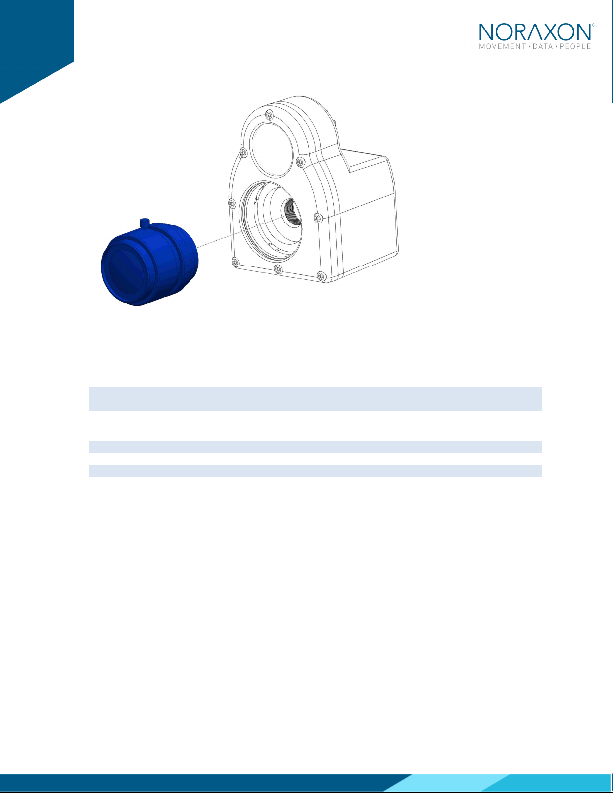
5.4 Select and attach your lens (300C only)
Select a lens based upon the field of view that is needed for your specific use-case. Refer to the Section
11.3 of the hardware manual for details on selecting the appropriate lens. The following fixed-focal
length lenses are available for use with this camera:
a. Navitar 3.5 mm
b. Navitar 4.5 mm
c. Navitar 6 mm
d. Navitar 12 mm
Ninox Hardware User Manual
12
(Rev B)
Once selected, carefully screw on the lens to the Ninox camera.
5.4.1 Aperture and Focal Adjustment
The C-mount lens used with the Ninox 300C has a set aperture and an adjustable focus. By rotating the
cylinder on the lens labeled ‘Near ---- ∞’, one can manually adjust the focus of the lens for each use
case.
Note: For extreme cases of bright or dark conditions, the aperture can be manually adjusted. See
Section 11.5 of this Manual for more information.
5.5 Determining USB Hub needs:
Note: Ninox cameras MUST be plugged into a USB3.0 port
Note: ONLY two Ninox cameras per USB controller or USB hub
Depending on the configuration, a USB hub may be required due to either a lack of USB ports on the
host computer or lack of sufficient power from the host computer. n either case, one of the following
setup options is required:
5.5.1 Unpowered USB3.0 hub
The recommended and tested USB3.0 hub is an Anker
The recommended and tested USB3.0 hub is an AnkerThe recommended and tested USB3.0 hub is an Anker
The recommended and tested USB3.0 hub is an Anker
4
44
4-
--
-port slim hub.
port slim hub.port slim hub.
port slim hub.
For up to two cameras, most computers can supply the power requirements needed for the cameras
and the USB hub directly through the USB port. Be sure to follow the guidelines for adjusting the
computer power settings Section 11.2.
When using an Anker slim hub or any unpowered USB hub, the following restrictions must be met for
proper function:
Max
MaxMax
Maximum
imumimum
imum of two cameras
The unpowered hub
CANNOT
CANNOTCANNOT
CANNOT run an active extension cable
The hub
m
mm
must
ustust
ust
be
bebe
be plugged into a USB3.0 port on the host computer
Ninox Hardware User Manual
13
(Rev B)
5.5.2 Powered USB3.0 Hub
The recommended and tested
The recommended and tested The recommended and tested
The recommended and tested powered
powered powered
powered USB3.0 hub is an Anker 7 port, USB3.0 powered hub.
USB3.0 hub is an Anker 7 port, USB3.0 powered hub.USB3.0 hub is an Anker 7 port, USB3.0 powered hub.
USB3.0 hub is an Anker 7 port, USB3.0 powered hub.
n some cases, the host computer is unable to provide the power necessary to run two Ninox cameras.
n this a scenario, the user must upgrade to a powered hub.
When using a powered USB3.0 hub, the following restrictions must be met for proper function:
A Maximum
Maximum Maximum
Maximum of 2 cameras at the recommended resolution and FPS.
A powered hub
W LL
W LLW LL
W LL run two cameras with an active extension cable (15m cable is available)
5.6 Adjusting Computer Performance Settings
mportant: The CPU, graphics card and power settings need to be adjusted on your computer for use
with MR3.
Before using your Ninox camera, you must adjust your computer settings to handle the high speed
video measurement and streaming within MR3. See Section Error!
Error! Error!
Error! Reference source not found.
Reference source not found.Reference source not found.
Reference source not found.1.2 for a
step by step description of how to adjust your computer settings.
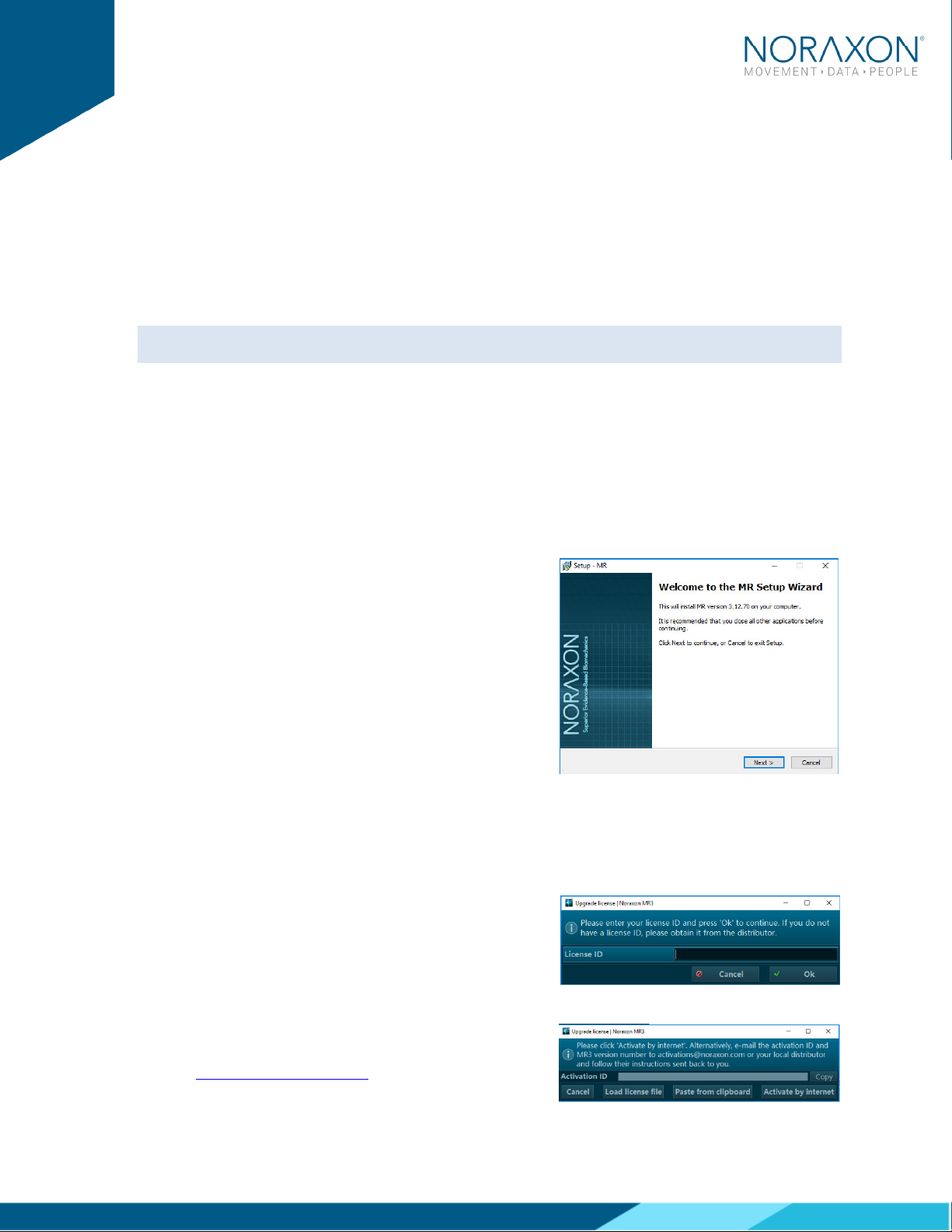
5.7 Installing the companion Software – myoResearch™ 3
To utilize the full functionality of the Ninox system, and ensure the system has updated drivers,
Noraxon’s myoResearch 3 needs to be installed on the computer.
Companion Software Installation
The Ninox Cameras are compatible with Noraxon MR3
software.
1. nsert the MR3 USB flash drive into the PC
2. A menu will automatically pop up
3. Click on the Noraxon installation file and follow the
Wizard’s instructions
Companion Software Activation
The installed companion software must be activated before unrestricted use is possible.
1. Open MR3
2. A dialog box will indicate how many more times
MR3 can be opened
3. Click on “Activate”
4. Enter the License D provided on your USB flash
drive and press “OK”
5. f you have an internet connection, click Activate by
nternet for immediate activation
6. Alternatively, email the provided activation D to
activation@Noraxon.com Noraxon Support will
Ninox Hardware User Manual
14
(Rev B)
email or respond by phone with the Activation Code. Enter the provided
Activation Code to remove any restrictions on use.
5.8 Device Communication (Driver) Software Installation
The Ninox camera requires the DS uEYE device driver which is pre-installed by the MR3 software
installation.
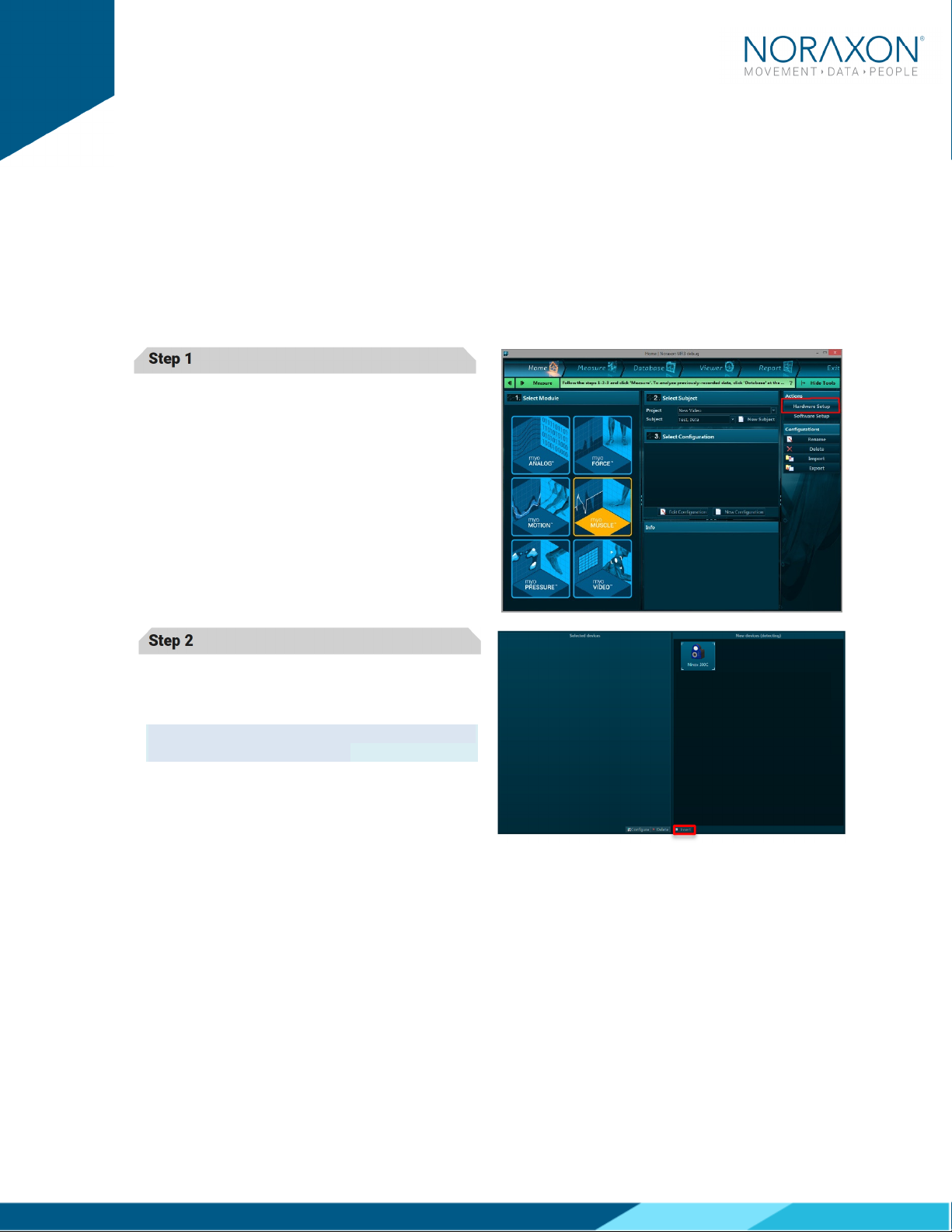
5.9 Configuring the Hardware
Before the Ninox can be used, the device software settings must be configured to adjust frame rate,
resolution, and other camera settings.
Step 1
Open MR3, typically listed under Noraxon ->
MR3
Click on the Hardware Setup
Hardware SetupHardware Setup
Hardware Setup button in the upper
right-hand corner.
Step 2
Select the Ninox icon, within the ‘New Device
‘New Device‘New Device
‘New Device’
’’
’
column, and click on the nsert
nsertnsert
nsert button.
Note: Make sure the Ninox camera is attached to
the USB port of the computer.

Ninox Hardware User Manual
15
(Rev B)
Step 3
The
Ninox Settings dialog will appear as shown.
A preview of the image will also be shown here.
Within the “
Settings” tab, select the desired
collection
frame rate (FPS).
Select a Resolution for recording. The
recommended resolution will show up based on
chosen FPS. See Sections 11.3 and 11.4
Sections 11.3 and 11.4Sections 11.3 and 11.4
Sections 11.3 and 11.4 for more
information on camera frame rate and resolution
options.
You may change the shutter time, environment,
and settings such as gain and gamma here.
Refer to S
SS
Section 7.1
ection 7.1ection 7.1
ection 7.1 to adjust these settings.
Note: f the camera image appears blurry
(especially with a Ninox 300C), the focus on the
lens may need to be adjusted. To do this, turn the
lens in the camera until the image appears clear.
Step 4
Click on OK (in the bottom of the dialog box)
when done.

Ninox Hardware User Manual
16
(Rev B)
6 Basic Operating Instructions
6.1 Recording a Measurement
Step 1
Within the Home screen, click on the myoV DEO
module icon.
Create a New Subject
Select New Configuration
New ConfigurationNew Configuration
New Configuration.
..
.
Step 2
nsert the devices to be used for the measurement
into the configuration by dragging a device in from
the list of A
AA
Available
vailable vailable
vailable D
DD
Devices
evicesevices
evices.
You may configure lens correction, image quality,
resolution, video speed, and other settings here.
Refer to Se
SeSe
Section 7.1
ction 7.1ction 7.1
ction 7.1 for information on these
settings.
More details about the fps and resolution settings
for the Ninox 300C can be found in Section 11.3
Section 11.3Section 11.3
Section 11.3 and
for the Ninox 125 can be found in Section 11.4
Section 11.4Section 11.4
Section 11.4.
Note: When working with the Ninox 300C, the various lens options make this camera robust to a wide
variety of work settings. Carefully select a lens based upon the field of view that is needed for your
specific use-case. nformation on how to choose a lens can be found in Section 11.3
Section 11.3Section 11.3
Section 11.3.
6.2 Enter into the Measurement Screen
Continue to the next step by selecting Measure.
Measure. Measure.
Measure.
6.3 Record Signal as Desired
After checking the quality of your picture, you are ready to record a measurement. Select Record
RecordRecord
Record at the
top left of the screen and begin your protocol. After completing your record, select Stop
StopStop
Stop and Save
SaveSave
Save. Save
the record as the name of your configuration, or type in a new name. After this, save your record or
Discard & measure again
Discard & measure againDiscard & measure again
Discard & measure again.
6.4 Storage and Protecting Between Use
For extended storage or when traveling:
Unplug the camera from the USB on the computer
Position all components (cameras and lenses) inside the travelling case according to their
prepared cavities.

Ninox Hardware User Manual
17
(Rev B)
7 Additional Ninox Settings and Features
7.1 Camera Settings
Located under Hardware Setup, each individual camera has a General Settings menu. The options
within this menu are detailed below:
Name:
Name:Name:
Name:
Allows the user to alter the name of each camera. This makes it easy to toggle between
cameras from within each personalized configuration.
Rotate:
Rotate:Rotate:
Rotate:
Allows the user to rotate the orientation of the image within the software.
Hardware Sync:
Hardware Sync:Hardware Sync:
Hardware Sync:
Must be selected if you would like to synchronize the video, via MyoSync, with other
cameras or other data streams
Note: This must be selected for each device that you would like synced.
Lens
LensLens
Lens
(
((
(Ninox 300C
Ninox 300CNinox 300C
Ninox 300C
only)
only)only)
only):
::
:
Select the lens that you are using for each camera to apply the appropriate lens
correction algorithm (removes any lens distortion).
Configure:
Configure:Configure:
Configure:
Must be selected to modify all the following settings (fps, resolution, etc.).
FPS:
FPS: FPS:
FPS: Select how many frames per second you would like to obtain throughout the measurement.
Higher frame rates are useful when using 2D marker tracking of high speed movements: running,
throwing, etc.. Lower frame rates may be suitable for those using the camera purely for reference.
Note: ncreasing the fps will decrease the maximum obtainable resolution
Resolution:
Resolution:Resolution:
Resolution:
Select the number of pixels that you would like to receive from the camera.
Shutter Time:
Shutter Time: Shutter Time:
Shutter Time: This setting alters the length of time that the camera’s image sensor is exposed to light.
Decreasing this value (increasing the denominator of the fraction) will expose the camera’s image
sensor to incoming light for a shorter period (useful when in very bright conditions – outdoors).
ncreasing this value (decreasing the denominator of the fraction) will expose the sensor to incoming
light for a longer period and will thereby cause the image to be brighter and add a blur to very high
speed movements. MR3 will recommend a shutter time based on the user selection of an indoor or
outdoor environment.
Environment
EnvironmentEnvironment
Environment
(
((
(Ninox
NinoxNinox
Ninox
300C
300C300C
300C
only)
only)only)
only):
::
:
Select whether you are collecting data in an indoor or outdoor
environment. This will alter the shutter time, gain, and gamma settings to a generic recommended
setting.
Note: Lighting slightly differs in every laboratory space, therefore minor adjustments to these
recommended values may be needed to optimize image quality.
Gain:
Gain:Gain:
Gain:
This setting amplifies the brightness of the entire image. ncreasing this value may be useful in
low-light environments. Be sure to always adjust the ambient lighting and the shutter time before
altering the gain.
Gamma:
Gamma:Gamma:
Gamma:
Gamma is an image correction value that will adjust the luminance of an image. Adjusting
gamma will make dark areas of the image darker and light areas lighter. A gamma value equal to 1 will
have no effect on the image, a gamma value <1 will shift the image towards the darker spectrum, and a
gamma value >1 will shift the image towards a lighter image spectrum. Be sure to always adjust the
ambient lighting and the shutter time before altering the gamma.
LED Light
LED LightLED Light
LED Light:
::
:
Select this option to turn the camera’s LED light on. This is useful when for 2D marker
tracking.

Ninox Hardware User Manual
18
(Rev B)
7.2 On-board LED light
The on-board LED light is meant specifically for improving reflective marker tracking. The light is NOT
meant to provide ambient lighting in low-light conditions. The keypad on the rear of the Ninox camera
provides three different brightness levels (low, medium, high). The brightness can be adjusted to
provide reflection from motion markers depending on ambient light conditions. However, to
automatically have the LED light turn on at the start of the measurement, one must select the LED light
option within the configuration (See Step 2 of Section 6.1)
7.3 Video Compression
All video files for the Ninox cameras are saved in a compressed format. The video compression occurs
at two different levels, real-time and post-process.
Real
RealReal
Real-
--
-time compression
time compressiontime compression
time compression - occurs as the video is streamed to the host computer. The video is
compressed real-time into m-jpeg format.
Post
PostPost
Post-
--
-process compression
process compressionprocess compression
process compression - can be executed after a record has been saved. The video will be further
compressed into an mpeg4 format to reduce file size. The post-process compression will reduce the
initial file size approximately 5-10X.
7.4 File Size
Due to the high frame rate and resolution capabilities of the Ninox cameras, large file sizes will be
created when recording. The following numbers are approximations of the file size per minute that can
be expected. The values listed are for a single camera.
Ninox 300C
Ninox 300CNinox 300C
Ninox 300C: 0.5 to 1 MB per minute, depending on the frame rate and resolution
Ninox
NinoxNinox
Ninox
125:
125:125:
125: 0.2 to 0.25 MB per minute, depending on the frame rate and resolution

Ninox Hardware User Manual
19
(Rev B)
8 Maintenance
8.1 Safety Precautions hen Cleaning
ARNING
Only use a damp cloth with mild soap and water or isopropyl
alcohol to clean the camera housing.
Do not immerse camera in any water or liquid.
8.2 Cleaning by Users
Clean the lens optical surface on a regular basis. The lens surface can be cleaned with isopropyl
alcohol or any window/lens cleaner.
8.3 Safety Precautions hen Performing Maintenance
No precautions required.
8.4 Maintenance by Users
No maintenance necessary.
8.5 Companion Software Updates
Perform a backup of the data folders to a separate drive as a precaution.
Click on the Patch/Update link provided in the email or as given on the Noraxon website.
Download the Patch/Update file.
To install the Patch/Update, click “Run” on the dialog box. No password is required.

Ninox Hardware User Manual
20
(Rev B)
9 Troubleshooting, Fault Diagnosis
9.1 Optimize Shutter time, Gamma and Gain settings
9.1.1 Overexposed image
n the case of an overexposed image (bright spots/glare) the following procedure can be followed, in
order, to optimize the video quality.
1. Begin by setting the gain to 0
2. Reduce the shutter time by increasing the shutter time divisor to further remove any
bright/glaring spots in the video
3. Once the bright spots have been removed, the gamma value can be adjusted to correct the
color representation and brighten dark areas in the video
Note: Best rule of thumb is to keep the gain value as low as possible while adjusting the shutter time
to remove bright/glaring spots.
9.1.2 Motion Blurring
n the case of a blurred video during high speed movements, the shutter time of the camera needs to
be reduced. This is assuming the lens has been fully focused in a static view.
Reducing the shutter time will reduce the amount of motion blur in the video. This is done by
increasing the “Shutter Time” divisor value. Shutter time values will automatically change when a
frame rate is selected. These values can be further increased to reduce any video motion blur.
9.2 Freezing or missed video frames
9.2.1 During real-time viewing
n the case where the video is freezing while viewing real-time, the likely issue is the USB
communication.
Potential solutions:
● Check if USB suspend is disabled (Section 11.2)
● Make sure the camera is plugged into a USB3 port
● Do not use more than two cameras per USB3 controller or USB hub
● Reduce the frame rate or resolution
9.2.2 Post video capture (saved video file)
During video recording, the cameras can heavily stress a computer's CPU and GPU. f the computer
CPU and GPU do not meet required specifications, video frames will be missed/lost in the recorded
video file. n the case where video freezing is only seen after the video has been recorded, the most
likely issues is poor computer performance.
Potential solutions:
● Check if the CPU and GPU settings have been correctly set as defined in Section 11.2
● Do not use more than two cameras per USB3 controller or USB hub
● Reduce the frame rate or resolution
9.3 Troubleshooting Chart
This manual suits for next models
2
Table of contents


