Nordelettronica NE185_20G User manual
NE185_20G
ISTRUZIONI D’USO
INSTRUCTIONS MANUAL
INSTRUCTIONS D’EMPLOI
BEDIENUNGSANLEITUNG
INSTRUCCIONES PARA EL USO
GB
D
F
I
E
95.0001.321 R.0

2

mod. NE185
182mm
98mm
64mm
3

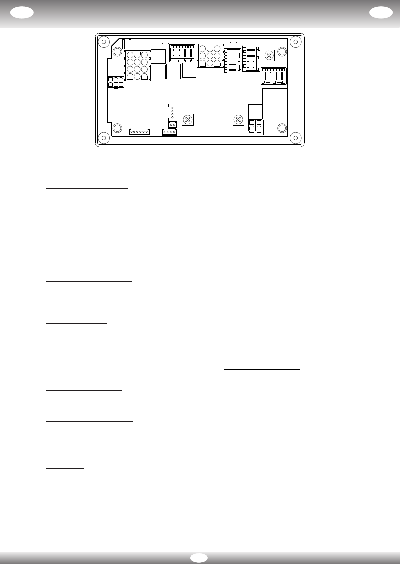
LEGENDA:
F1: Fusibile 5A collegato alla batteria auto per l'alimentazione delle luci side marker.
F2: Fusibile 20A collegato alla batteria servizi per l'alimentazione del frigo.
F3: Fusibile 30A/20A collegato direttamente alla batteria servizi per l’alimentazione WEBASTO (30A)
o AUX (20A).
F4: Fusibile 15A collegato direttamente alla batteria servizi per l’alimentazione scalino
F5: Fusibile 15A collegato all'interruttore generale luci per alimentare il gruppo Luci_1
F6: Fusibile 15A collegato all'interruttore generale luci per alimentare il gruppo Luci_2.
F7: Fusibile 10A collegato direttamente alla batteria servizi per le accensioni del frigo, stufa e
all'interruttore pompa per l'alimentazione della pompa acqua
F8: Fusibile 10A collegato direttamente alla batteria servizi per alimentare le luci di cortesia e
all’interruttore luce esterna
F9: Fusibile 15A collegato alle uscite AUX
Attenzione:
In caso di sostituzione di fusibili guasti rispettare il valore di amperaggio previsto.
FUNZIONAMENTO:
Utenze azionate dal pannello comandi:
Le uscite luci interne (luci_1 e luci_2), luce esterna e pompa sono azionate direttamente dai relativi
tasti del pannello comandi.
- Se la tensione di batteria servizi rimane sotto i 10,5V per più di tre minuti, il derivatore NE185 spegne
automaticamente tutte le utenze luci e pompa. Per riattivare i carichi bisogna premere i
corrispondenti tasti sul pannello comandi, ma se la batteria permane sotto i 10,5V dopo tre minuti si
disattiveranno nuovamente. In questo caso è consigliabile staccare tutti i carichi con il maniglione
stacca batteria e ricaricare la batteria servizi entro 2 giorni.
Ricarica batteria auto:
Quando e’ presente la rete 230V, il derivatore provvede a ricaricare anche la batteria auto con una
corrente di circa 2A. La carica si attiva automaticamente non appena la tensione della batteria
servizi supera quella della batteria auto.
Segnale side-marker:
L’uscita side-marker può essere attivata con un comando negativo (massa) sul blocchetto JP13 pin 5
o con un comando positivo (+12V) sul blocchetto JP13 pin 4.
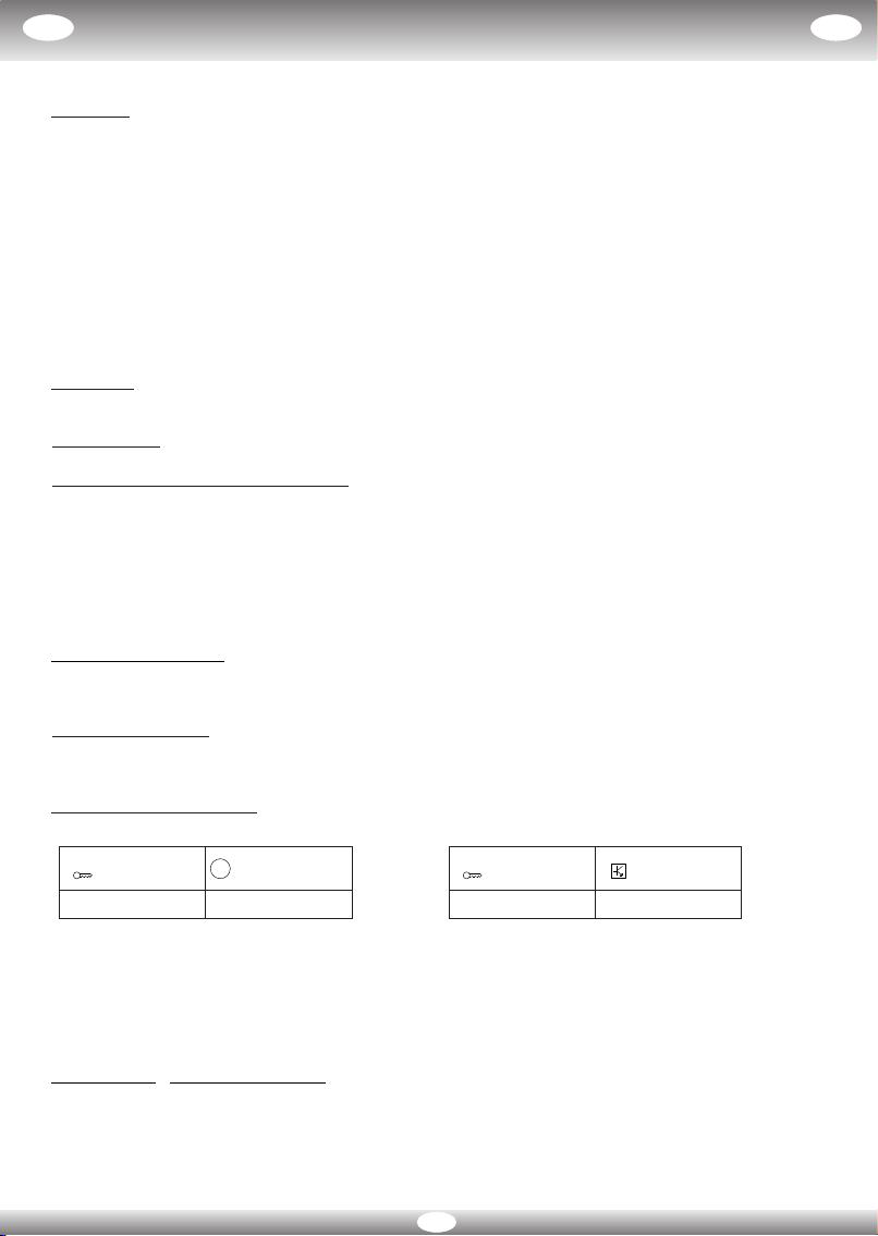
Utenze azionate dal D+:
Il relè accoppiatore ed il relè frigo si abilitano immediatamente in presenza di una di queste due
(1)
condizioni:
oppure
Il relè accoppiatore provvede alla ricarica della batteria servizi tramite l'alternatore con motore in
(1)
moto. Il relè frigo permette di alimentare a 12V il frigo trivalente sempre quando il motore è in moto.
La luce esterna si spegne automaticamente con il motore in moto.
(1)
Se è presente il collegamento tra J14 e J15 il relè accoppiatore non si abilita.
(presenza convertitore DC/DC esterno)
ATTENZIONE: Convertitore DC/DC:
Se si utilizza il convertitore DC/DC per caricare la batteria servizi, eseguire il
collegamento tra J14 e J15. In questa modalità il relè accoppiatore (RE1) non si
abilita quando il mezzo è in moto.
In caso di inutilizzo del mezzo e di assenza collegamento 230V scollegare la batteria servizi con il
maniglione stacca batteria.
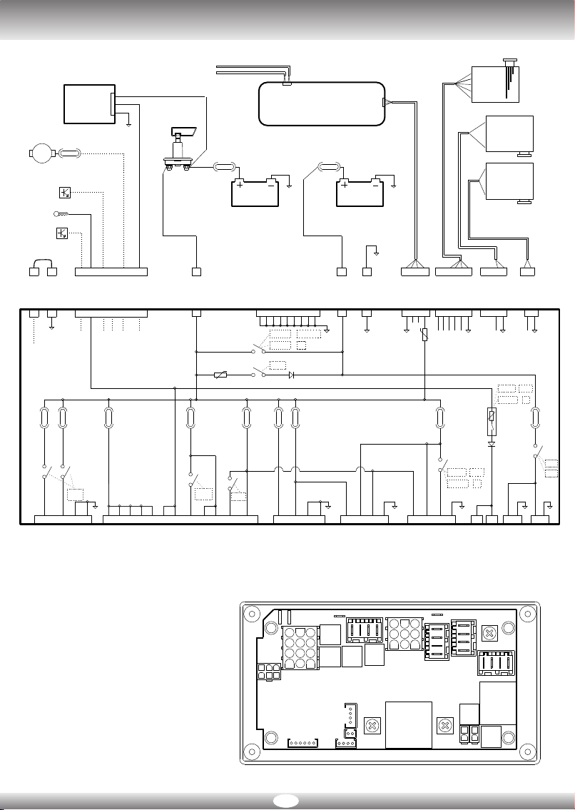
DERIVATORE NE185_20G
+Chiave
JP13 pin 1 D+
JP13 pin 6
D+
KEY-ON
+12V attivo
II
4
+Alternatore
JP13 pin2
+12V
G
+Chiave
JP13 pin 1
KEY-ON
+12V
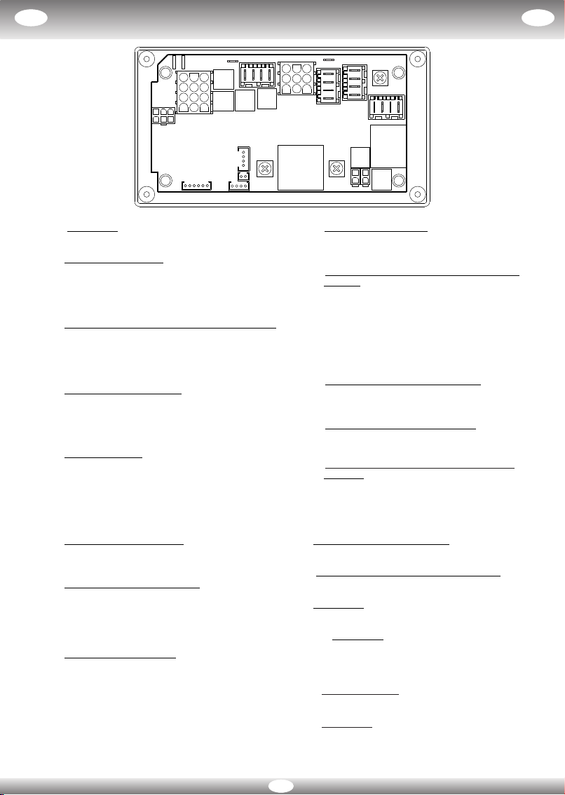
JP1 : NEGATIVO
1.2.3.4.5.6.7.8.9: NEGATIVO
JP2: USCITA LUCI (NERO)
1. LUCI_2 (+) (F6 15A)
2. LUCI_1 (+) (F5 15A)
3. NEGATIVO
4. NEGATIVO
JP3: USCITA SCALINO, WEBASTO/AUX (ROSSO)
1. Uscita (+) WEBASTO/AUX (F3 30A )/20A
2. Uscita (+) SCALINO (F4 15A)
3. NEGATIVO
4. NEGATIVO
JP4: USCITA FRIGO (BIANCO)
1. Uscita (+) frigo diretta (F2 20A)
2. Uscita (+) frigo azionata da relè (F2 20A)
3. Alimentazione accensione gas (+) (F7 10A)
4. NEGATIVO
JP5: USCITA UTENZE
1,4,5,7,8. Uscita (+) AUX (F9 15A)
9. Accensione STUFA (F7 10A)
12. Uscita (+) POMPA (F7 10A)
6. Uscita (+) LUCE ESTERNA (F8 10A)
2,3 . Uscita (+) LUCI CORTESIA (F8 10A)
10,11. Uscita rientro scalino (max 1A)
JP7: SERBATOI recupero (R1)
1. NEGATIVO
2. FULL Serbatoio recupero R1
JP8: SERBATOI recupero (R2-R3)
1. NEGATIVO
2. FULL Serbatoio recupero R2
3. NEGATIVO
4. FULL Serbatoio recupero R3
JP9: SERBATOI potabile (S1)
1. NEGATIVO
2. 1/4 Serbatoio acqua potabile S1
3. 2/4 Serbatoio acqua potabile S1
4. 3/4 Serbatoio acqua potabile S1
5. 4/4 Serbatoio acqua potabile S1
6. N.c.
JP11: PANNELLO COMANDI
Connettore 4 poli per il collegamento del pannello
comandi tramite l'apposito cavo.
JP13: INGRESSO COMANDI D+, SIDE MARKER,
P. RETE
1. Ingresso + Chiave (C036L1A -13)
2. Ingresso D+ dall'alternatore
3. Ingresso PRESENZA RETE dal carica batterie
4. Ingresso Side Marker comando positivo
5. Ingresso Side Marker comando negativo
(C036L1A -11)
6. Ingresso D+ comando negativo (C036L1A -2)
JP14: USCITA SIDE MARKER SINISTRO
1. Uscita (+) Side Marker sx (F1 5A)
2. NEGATIVO
JP15: USCITA SIDE MARKER DESTRO
1. Uscita (+) Side Marker dx (F1 5A)
2. NEGATIVO
JP16: PREDISPOSIZIONE PANNELLO SOLARE
(VERDE)
1. Libero (F2 20A)
2. Pannello Solare +Batteria Servizi (F4 15A)
3. Libero (F7 10A)
4. NEGATIVO
J1: INGRESSO BATTERIA AUTO
1. Ingresso + batteria AUTO (B1)
J2: INGRESSO BATTERIA SERVIZI (NERO)
1. Ingresso + batteria SERVIZI (B2)
J3: NEGATIVO
1. NEGATIVO
J4, J5 : USCITA D+
Uscita positiva (ptc 0,5A) per azionare tutti i carichi
funzionanti con motore in moto (es. frigo AES,
rientro antenna, valvole di scarico, ecc)
J14 : Presenza DC-DC
1. Presenza DC-DC (si collega al NEGATIVO)
J15 : NEGATIVO
DERIVATORE NE185_20G II
5
61
21 3
8
5
2
7
1
4
9
3
6
5
8
4
7
6
9
1110 12
4
1
JP11
JP9
JP5
JP2
JP3
RE1
RE6
RE3 RE2 RE8
RE4
1
2
4
3
124
3
J2
JP1
JP4
124
3
B2 B1
J1
J3
-
J4 J5
JP16
1
2
4
3
1
JP8
2
1
JP14
RE9
2
1
JP15
JP13
3
12
6
45
J14 J15
RE10
JP7
1
SHUNT NE185_20G
LEGEND:
F1: 5A fuse connected to the vehicle battery to power the side marker lights
F2: 20A fuse connected to the service battery to power the fridge
F3: 30A/20A fuse connected directly to the service battery to power the Webasto (30A)
or Auxiliary (20A)
F4: 15A fuse connected directly to the service battery to power the step
F5: 15A fuse connected to lights master switch to power the group of lights_1
F6: 15A fuse connected to lights master switch to power the group of lights_2
F7: 10A fuse connected directly to the service battery to turn on the fridge and heater and to the pump
switch to power the water pump
F8: 10A fuse connected directly to the service battery to the courtesy light and external light switch
F9: 15A fuse connected to the AUX outputs
Attention:
When replacing faulty fuses, observe the correct amperage.
OPERATION:
Power activated from control panel:
The outputs for internal lights (lights_1 and lights_2), external light and pump are activated directly
by the relevant keys on the control panel.
-If the service battery voltage remains under 10,5V for over three minutes, the NE185 shunt
automatically turns off all the power for lights and pump. To recharge press the relevant keys on
the control panel. If the battery is still under 10,5V, it will be deactivated again after three
minutes. In this case is advisable to disconnect all loads with the battery main switch and
recharge the battery services within 2 days.
Car battery recharge:
If there is the main supply 230V, the shunt charges the car battery with a current of about 2A. The
charge is activated automatically when the battery voltage exceeds the services of the car battery.
Side marker signal:
The side-marker output can be activated with a negative control (negative) on the JP13 block pin 5,
or with a positive control (+12V) on the JP13 block pin 4.
Services activated by D+:
The coupler relay and fridge relay are enabled immediately in one of these two conditions:
(1)
or
The coupler relay recharges the service battery with the alternator when the engine is running.
(1)
The fridge relay powers the three purpose fridge at 12V when the engine is running.
With the engine running the external light automatically turns itself off.
(1)
If there is a connection between J14 and J15 the coupler relay is not enabled.
(presence of external DC / DC converter)
ATTENTION: DC / DC converter:
If you use the DC / DC converter to charge the services battery, make the
connection between J14 and J15.
In this mode the coupler relay (RE1) is not enabled when the engine is running.
If the vehicle not in use and the connection 230V is not present disconnect the battery service with
the battery main switch.
+key
JP13 pin 1 D+
JP13 pin 6
D+
KEY-ON
+12V on
GBGB
6
+Alternator
JP13 pin2
+12V
G
+key
JP13 pin 1
KEY-ON
+12V
JP1 : NEGATIVE
1.2.3.4.5.6.7.8.9: NEGATIVE
JP2: LIGHT OUTPUT (BLACK)
1. LIGHTS_2 (+) (F6 15A)
2. LIGHTS_1 (+) (F5 15A)
3. NEGATIVE
4. NEGATIVE
JP3: STEP OUT, TRUMA (RED)
1. Webasto / Auxiliary output (+) (F3 30A/20A)
2. STEP output (+) (F4 15A)
3. NEGATIVE
4. NEGATIVE
JP4: FRIDGE OUTPUT (WHITE)
1. Direct fridge output (+) (F2 20A)
2. Fridge output (+) activated by relay (F2 20A)
3. Gas ignition power supply (+) (F7 10A)
4. NEGATIVE
JP5: POWER OUTPUTS
AUX output (+) 1,4,5,7,8. (F9 15A)
9. (F7 10A)Heater ignition output (+)
12. (F7 10A)PUMP output (+)
6. (F8 10A) External light output (+)
2,3 . (F8 10A)Courtesy light output (+)
10,11. (max 1A)Output step in
JP7: RECYCLE TANKS (R1)
1. NEGATIVE
2. FULL recycle tanks R1
JP8: RECYCLE TANKS (R2-R3)
1. NEGATIVE
2. FULL recycle tanks R2
3. NEGATIVE
4. FULL recycle tanks R3
JP9: TANKS (S1)
1. NEGATIVE
2. 1/4 drinking water tank S1
3. 2/4 drinking water tank S1
4. 3/4 drinking water tank S1
5. 4/4 drinking water tank S1
6. N.c.
JP11: CONTROL PANEL
4-pole connector to connect the control panel with
the cable provided.
JP13: D+ CONTROL INPUT, SIDE MARKER ,
POWER MAIN
1. +Key-on input (C036L1A -13)
2. D+ input from alternator
3. POWER MAINS ON input from battery charger
4. Side Marker positive control input
5. Side Marker negative control input (C036L1A-11)
6. D+ negative control input (C036L1A -2)
JP14: SIDE MARKER LEFT OUTPUT
1. Side Marker left output (+) (F1 5A)
2. NEGATIVE
JP15: SIDE MARKER RIGHT OUTPUT
1. Side Marker right output (+) (F1 5A)
2. NEGATIVE
JP16: OPTION FOR SOLAR PANEL (GREEN)
1. Free (F2 20A)
2. SOLAR PANEL +Service Battery (F4 15A)
3. Free (F7 10A)
4. NEGATIVE
J1: AUTO BATTERY INPUT
Input +CAR battery (B1)
J2: SERVICE BATTERY INPUT
Input + LEISURE battery (B2)
J3: NEGATIVE
NEGATIVE
J4, J5 : D+ OUTPUT
Positive output (ptc 0.5A) to activate all charges
operating with engine running (e.g. fridge AES,
aerial entry, discharge valves, etc.)
J14 : PRESENCE DC-DC
1. Presence DC-DC (connects to the negative)
J15 : NEGATIVE
SHUNT NE185_20G GBGB
7
61
21 3
8
5
2
7
1
4
9
3
6
5
8
4
7
6
9
1110 12
4
1
JP11
JP9
JP5
JP2
JP3
RE1
RE6
RE3 RE2 RE8
RE4
1
2
4
3
124
3
J2
JP1
JP4
124
3
B2 B1
J1
J3
-
J4 J5
JP16
1
2
4
3
1
JP8
2
1
JP14
RE9
2
1
JP15
JP13
3
12
6
45
J14 J15
RE10
JP7
1
PORTEFUSIBLE NE185_20G
LEGENDE:
F1: Fusible 5 A relié à la batterie du véhicule pour alimenter les phares side marker
F2: Fusible 20A connecté à la batterie de service pour l'alimentation du frigo.
F3: Fusible 30A/20A directement connecté à la batterie de service pour l'alimentation Webasto (30A)
ou Auxiliaires (20A)
F4: Fusible 15A directement connecté à la batterie de service pour l'alimentation de la marche
F5: Fusible 15A connecté à l'interrupteur général des lumières pour alimenter le groupe éclairages_1
F6: Fusible15A connecté à l'interrupteur général des lumières pour alimenter le groupe
éclairages_2
F7: Fusible 10A directement connecté à la batterie de service pour l'allumage du frigo et de la
chaudière, ainsi qu'à l'interrupteur de la pompe pour l'alimentation de la pompe à eau
F8: Fusible 10A connecté à l'interrupteur de l'éclairage extérieur et des veilleuses
F9: Fusible 15A connecté aux sorties auxiliaires
Attention:
En cas de remplacement de fusibles usagés respecter la valeur de l'ampérage prévue.
FONCTIONNEMENT:
Eléments actionnés depuis le panneau de commande:
Les sorties éclairages intérieurs (éclairages_1 et éclairages_2), éclairage extérieur et pompe sont
directement pilotées par les touches du panneau de commande.
- Si la tension de la batterie de service reste sous les 10,5V pendant plus de trois minutes, le
dérivateur Ne185 coupe automatiquement les éléments suivants: éclairages et pompe.
Pour en rétablir les charges, presser les touches correspondantes sur le panneau de commande,
mais si la batterie reste sous les 10,5V, ils seront à nouveau désactivés. Dans ce cas est conseillé
de débrancher toutes les charges avec l'interrupteur principal de la batterie, et recharger la batterie
des services dans les 2 jours.
Rechargement batterie du vehicule:
Quand il y a un réseau 230v, le portafusible recharge les batteries auto avec du courant 2A. La
recharge s'active automatiquement dès que la tension de la batterie de service dépasse celle de la
batterie auto.
Signal side-marker :
Les sorties side-marker peuvent être activées par une commande négative (masse) sur le bloc JP13
pointe 5, ou par une commande positive (+12 V) sur le bloc JP13 pin 4.
Usagers actionnés par D+ :
Le relais coupleur et le relais frigo entrent immédiatement en service quand :
(1)
ou
Le relais de couplage assure la recharge de la pile services par le biais de l'alternateur lorsque le
(1)
moteur est en marche. Le relais frigo permet d'alimenter à 12V le frigo trivalent, moteur en marche.
L'éclairage extérieur s'éteint automatiquement avec le moteur en marche.
(1)
S'il y a une connexion entre J14 et J15, le relais de coupleur n'est pas activé.
(présence de convertisseur DC / DC externe)
ATTENTION: Convertisseur DC / DC:
Si vous utilisez le convertisseur DC / DC pour charger la batterie de services, établissez
la connexion entre J14 et J15.
Dans ce mode, le relais de coupleur (RE1) n'est pas activé lorsque le moteur tourne.
En cas de non utilisation du véhicule et sans connexion à 230V débranchez la batterie service avec
l'interrupteur principal de batterie.
+Clé
JP13 pin 1 D+
JP13 pin 6
D+
KEY-ON
+12V activé
FF
8
+Alternateur
JP13 pin2
+12V
G
+Clé
JP13 pin 1
KEY-ON
+12V

PORTEFUSIBLE NE185_20G
JP1 : NEGATIF
1.2.3.4.5.6.7.8.9: NEGATIF
JP2: SORTIES ECLAIRAGES (NOIR)
1. ECLAIRAGES_2 (+) (F6 15A)
2. ECLAIRAGES_1 (+) (F5 15A)
3. NEGATIF
4. NEGATIF
JP3: SORTIE MARCHE, TRUMA (ROUGE)
1. Sortie (+) Webasto / Auxiliaires (F3 30A/20A)
2. Sortie (+) MARCHE (F4 15A)
3. NEGATIF
4. NEGATIF
JP4: SORTIE FRIGO (BLANC)
1. Sortie (+) frigo directe (F2 20A)
2. Sortie (+) frigo actionnée par relais (F2 20A)
3. Alimentation allumage gaz (+) (F7 10A)
4. NEGATIF
JP5: SORTIE USAGES
Sortie (+) AUX 1,4,5,7,8. (F9 15A)
9. (F7 10A)Sortie (+) allumage chauffe
12. (F7 10A)Sortie (+) POMPE
6. (F8 10A)Sortie (+) eclairage exterieu
2,3 . (F8 10A)Sortie (+) Veilleuse
10,11. (max 1A)Sortie rentrée de la marche
JP7: RESERVOIRS de récupération (R1)
1. NEGATIF
2. FULL Réservoir de récupération R1
JP8: RESERVOIRS de récupération (R2-R3)
1. NEGATIF
2. FULL Réservoir de récupération R2
3. NEGATIF
4. FULL Réservoir de récupération R3
JP9: RESERVOIRS potable (S1)
1. NEGATIF
2. 1/4 Réservoir eau potable S1
3. 2/4 Réservoir eau potable S1
4. 3/4 Réservoir eau potable S1
5. 4/4 Réservoir eau potable S1
6. N.c.
.
JP11: PANNEAU DE COMMANDE
Connecteur 4 pôles pour la connexion du panneau
de commande par le câble prévu
JP13: ENTREE COMMANDES D+, SIDE MARKER,
PRESENCE RESEAU
1. Entrée +Clé (C036L1A -13)
2. Entrée D+ depuis l’alternateur
3. Entrée PRESENCE RESEAU depuis le chargeur
de batterie
4. Entrée Side Marker commande positive
5. Entrée Side Marker commande négative
C036L1A -11)
6. Entrée D+ commande négative (C036L1A -2)
JP14: SORTIE SIDE MARKER GAUCHE
1. Sortie (+) Side Marker gauche (F1 5A)
2. NEGATIF
JP15: SORTIE SIDE MARKER DROIT
1. Sortie (+) Side Marker droit (F1 5A)
2. NEGATIF
JP16: PREPARER LE PANNEAU SOLAIRE (VERT)
1. Libre (F2 20A)
2. Ponneau Solaire +Batterie Service (F4 15A)
3. Libre (F7 10A)
4. NEGATIF
J1: ENTREE BATTERIE DE AUTO
1. Entrée + batterie AUTO (B1)
J2: ENTREE BATTERIE DE SERVICE
1. Entrée + batterie SERVICE (B2)
J3: ENTREE NEGATIF
1. NEGATIF
J4, J5 : SORTIE D+
Sortie positive (ptc 0,5A) pour actionner toutes les
charges en fonction lorsque le moteur est en marche
(ex.: frigo AES, escamotage antenne, soupapes
d'échappement, etc...).
J14 : Présence de DC-DC
1. Présence de DC-DC (se connecte au NÉGATIF)
J15 : NEGATIF
FF
9
61
21 3
8
5
2
7
1
4
9
3
6
5
8
4
7
6
9
1110 12
4
1
JP11
JP9
JP5
JP2
JP3
RE1
RE6
RE3 RE2 RE8
RE4
1
2
4
3
124
3
J2
JP1
JP4
124
3
B2 B1
J1
J3
-
J4 J5
JP16
1
2
4
3
1
JP8
2
1
JP14
RE9
2
1
JP15
JP13
3
12
6
45
J14 J15
RE10
JP7
1
ABZWEIGDOSE NE185_20G
ZEICHENERKLÄRUNG:
F1: Sicherung 5A angeschlossen an die Autobatterie zur Versorgung der Side Marker Lichter
F2: Sicherung 20A an die Servicebatterie den Kühlschrank.
F3: Sicherung 30A/20A direkt an die Servicebatterie für die Webasto oder Zusätzlich (30A)
Versorgung angeschlossen (20A).
F4: Sicherung 15A direkt an die Servicebatterie für die elektrische Stufe angeschlossen
F5: Sicherung 15A angeschlossen an den Hauptlichtschalter für die Lichtgruppe_1
F6: Sicherung 15A angeschlossen an den Hauptlichtschalter für die Lichtgruppe_2
F7: Sicherung 10A direkt an die Servicebatterie angeschlossen für das Einschalten des
Kühlschranks, Ofens und der Wasserpumpe
F8: Sicherung 10A angeschlossen an den Schalter der Außenbeleuchtung und des Tür-Innenlichts
F9: Sicherung 15A angeschlossen zu den Hilfsausgängen
Achtung:
Beim Auswechseln defekter Sicherungen auf den vorgeschriebenen Amperewert achten.
BETRIEB:
Über das Schaltfeld gesteuerte Verbraucher:
Die Ausgänge Innenbeleuchtung (Licht_1 und Licht_2), Außenbeleuchtung und Pumpe werden
direkt über die entsprechenden Tasten auf dem Schaltfeld gesteuert.
- Sinkt die Spannung der Servicebatterie länger als drei Minuten unter 10,5V ab, schaltet die
Abzweigdose Ne185 automatisch alle Lichter und die Pumpe. Zum erneuten Einschalten die
entsprechenden Tasten auf dem Schaltfeld drücken; bleibt die Batterie nach drei Minuten immer
noch unter 10,5V, schalten sie automatisch wieder aus.In diesem Fall ist es ratsam alle Lasten mit
dem Batterie-Hauptschalter unterbrechen und Aufladen der Batterie Service innerhalb von 2
Tagen.
Aufladen der Auto-Batterie:
Man aufgeladen die Fahrzeugbatterie über dasabzweigdose, wenn es mit 230V Strom versorgt wird.
Wenn die Servicebatterie Spannung ist auf die Fahrzeugbatterie Spannung, beliefert das Ladegerät max 2
Amp zu der Fahrzeugbatterie
Side-Marker-Signal:
Der Side-Marker Ausgang kann mit einem negativen Signal (Masse) auf der 5-Pin-Steckbuchse JP13,
oder mit einem positiven Signal (+12V) auf der 4-Pin-Steckbuchse JP13 aktiviert werden.
Von D+ versorgte Stromverbraucher:
Das Koppelrelais und das Kühlschrankrelais werden bei Vorhandensein einer dieser beiden
(1)
Konditionen sofort aktiviert.:
oder
Das Koppelrelais ladet die Servicebatterie bei laufendem Motor über den Wechselstromgenerator
(1)
auf. Das Kühlschrankrelais versorgt bei laufendem Motor den Kühlschrank mit 12V.
Die Außenbeleuchtung schaltet automatisch ab, wenn der Motor gestartet wird.
(1)
Wenn die Verbindung zwischen J14 und J15 besteht, ist das Koppler-Relais nicht aktiviert.
(Vorhandensein eines externen DC / DC-Wandlers)
WARNUNG: DC / DC-Wandler:
Wenn Sie den Service-Akku mit dem DC / DC-Wandler laden, stellen Sie die Verbindung
zwischen her J14 und J15. In diesem Modus ist das Koppelrelais (RE1) nicht aktiviert,
wenn das Fahrzeug in Bewegung ist.
Wenn das Fahrzeug nicht in Gebrauch ist und die Verbindung 230 nicht vorhanden ist, trennen Sie das
Service-Batterie mit dem Batterie-Hauptschalter.
+Schlüssel
JP13 pin 1 D+
JP13 pin 6
D+
KEY-ON
+12V aktiviert
DD
10
Wechselstromgenerator
JP13 pin2
+12V
G
+Schlüssel
JP13 pin 1
+12V
KEY-ON

ABZWEIGDOSE NE185_20G
JP1 : NEGATIV
1.2.3.4.5.6.7.8.9: NEGATIV
JP2: LICHTAUSGANG (SCHWARZ)
1. LICHTGRUPPE_2 (+) (F6 15A)
2. LICHTGRUPPE_1 (+) (F5 15A)
3. NEGATIV
4. NEGATIV
JP3: AUSGANG ELEKTRISCHE STUFE, TRUMA
(ROT)
1. Ausgang (+) Webasto/Zusätzlich (F3 30A/20A)
2. Ausgang (+) Ofens (F4 15A)
3. NEGATIV
4. NEGATIV
JP4: KÜHLSCHRANKAUSGANG (WEISS)
1. Ausgang (+) Kühlschrank, direkt (F2 20A)
2. Ausgang (+) vom Relais versorgter
Kühlschrank (F2 20A)
3. Gasanzünder (+) (F7 10A)
4. NEGATIV
JP5: AUSGÄNGE
Ausgang (+) AUX1,4,5,7,8. (F9 15A)
9. (F7 10A)Ausgang (+) Ofeneinschaltung
12. (F7 10A) Ausgang (+) PUMPE
6. (F8 10A)Ausgang (+) Außenbeleuchtung
2,3 . (F8 10A) Ausgang (+) Tür.-Innenlicht
10,11. Ausgang Einziehen der
elektrischen Stufe (max 1A)
JP7: ABWASSERTANK (R1)
1. NEGATIV
2. FULL Abwassertank R1
JP8: ABWASSERTANK(R2-R3)
1. NEGATIV
2. FULL Abwassertank R2
3. NEGATIV
4. FULL Abwassertank R3
JP9: (S1)TRINKWASSERTANK
1. NEGATIV
2. 1/4 S1 Trinkwassertank
3. 2/4 S1Trinkwassertank
4. 3/4 S1Trinkwassertank
5. 4/4 S1Trinkwassertank
6. N.c.
JP11: SCHALTFELD
4-poliger Schalter für den Anschluss des
Schaltfeldes mit Hilfe des vorgesehenen Kabels.
JP13: ,EINGANG BEFEHLE D+, SIDE MARKER
NETZSTROM
1. (C036L1A -13)Eingang + Schlüssel
2. Eingang D+ über Wechselstromgenerator
Eingang NETZSTROM von Ladegerät3.
Eingang Side Marker positiver Signal 4.
Eingang Side Marker negatives Signal 5.
(C036L1A -11)
6. (C036L1A -2)Eingang D+ negativer Befehl
JP14: AUSGANG SIDE MARKER LINK
1. Ausgang (+) Side Marker links (F1 5A)
2. NEGATIV
JP15: AUSGANG SIDE MARKER RECHT
1. Ausgang (+) Side Marker rechts (F1 5A)
2. NEGATIV
JP16: ANSCHLÜSSE FÜR SONNENPANEEL (GRÜN)
1. Frei (F2 20A)
2. Verkleidung Solar +Servicebatterie (F4 15A)
3. Frei (F7 10A)
4. NEGATIV
J1: EINGANG AUTOBATTERIE
1. Eingang + AUTOBATTERIE (B1)
J2: EINGANG SERVICEBATTERIE
1. Eingang + SERVICEBATTERIE (B2)
J1: NEGATIVEINGANG
1. NEGATIV
J4, J5: AUSGANG D+
Positiver Ausgang (ptc 0,5A) für die Aktivierung aller
funktionierenden Verbraucher bei laufendem Motor
(z.B. Kühlschrank AES, Einfahren der Antenne,
Ablaufventile, usw)
J14 : DC-DC Präsenz
1. DC-DC Präsenz
(verbindet sich mit dem NEGATIV)
J15 : NEGATIV
DD
11
61
21 3
8
5
2
7
1
4
9
3
6
5
8
4
7
6
9
1110 12
4
1
JP11
JP9
JP5
JP2
JP3
RE1
RE6
RE3 RE2 RE8
RE4
1
2
4
3
124
3
J2
JP1
JP4
124
3
B2 B1
J1
J3
-
J4 J5
JP16
1
2
4
3
1
JP8
2
1
JP14
RE9
2
1
JP15
JP13
3
12
6
45
J14 J15
RE10
JP7
1

DERIVADOR NE185_20G
LEYENDA:
F1: Fusible 5A conectado a la batería vehículo para alimentar las luces side marker
F2: Fusible 20A conectado a la batería de servicios para la alimentación del frigorífico
F3: Fusible 30A/20A conectado directamente a la batería de servicios para la alimentación
Webasto o Aux (30A) (20A)
F4: Fusible 15A conectado directamente a la batería de servicios para la alimentación del escalón
F5: Fusible 15A conectado al interruptor general luces para alimentar el grupo luces_1
F6: Fusible 15A conectado al interruptor general luces para alimentar el grupo luces_2
F7: Fusible 10A conectado directamente a la batería de servicios para los encendidos del
frigorífico, estufa y al interruptor bomba para la alimentación de la bomba del agua
F8: Fusible 10A conectado directamente a la batería de servicios para alimentar las luces de
cortesía y al interruptor de la luz exterior
F9: Fusible 15A conectado al las salidas auxiliares
Atención:
En caso de sustitución de fusibles averiados, hay que respetar el valor de amperaje previsto.
FUNCIONAMIENTO:
Utilizaciones accionadas por el panel de mandos:
Las salidas de luces interiores (luces_1 y luces_2), luz exterior y bombason, se gestionan directamente
por las correspondientes teclas del panel de mandos.
- Si la tensión de la batería servicios permanece por debajo de los 10,5V durante más de tre minutos, el
derivador NE185 apaga automáticamente todas las utilizaciones luces y bomba. Para reactivar las
cargas hay que pulsar las teclas correspondientes en el panel de mandos, pero si la batería permanece
por debajo de los 10,5V transcurrido tre minutos se desactivarán nuevamente. En este caso es
aconsejable desconectar todas las cargas con el interruptor principal de la batería y recargar la batería
de servicio dentro de 2 días.
Carga batería auto:
Cuando la red es de 230V, el derivador cargará la batería del vehículo con una corriente de
alrededor de 2A. La carga se activa automáticamente cuando el voltaje de la batería los servicios
excede de la batería del vehículo.
Señal side-marker:
La salida side-marker puede activarse con un mando negativo (masa) en el bloque JP13 pin 5, o con
un mando positivo (+12V) en el bloque JP13 pin 4.
Utilizaciones accionadas por el D+:
El relé acoplador y el relé nevera se habilitan inmediatamente si hay una de estas dos
(1)
condiciones:
o
El relé acoplador efectúa la recarga de la batería de servicios mediante el alternador con motor en
(1)
marcha. El relé frigorífico permite alimentar a 12V el frigorífico trivalente siempre cuando el motor
está en marcha. La luz exterior se apaga automáticamente con el motor en marcha.
Si la conexión entre J14 y J15 está presente, el relé de acoplamiento no está habilitado.
(1)
(presencia de convertidor DC / DC externo)
ATENCIÓN: Convertidor DC / DC:
Si está utilizando el convertidor de DC/DC para cargar la batería de servicio, establezca
la conexión entre J14 y J15.
En este modo, el relé de acoplamiento (RE1) no se activa cuando el motor está en
funcionamiento.
Si el vehículo no está en uso y el enlace 230 no está presente, desconecte la batería en servicio con el
interruptor principal de la batería.
+Llave
JP13 pin 1 D+
JP13 pin 6
D+
KEY-ON
+12V activado
EE
12
+Alternador
JP13 pin2
+12V
G
+Llave
JP13 pin 1
KEY-ON
+12V

JP1 : NEGATIVO
1.2.3.4.5.6.7.8.9: NEGATIVO
JP2: ALIDA LUCES (NEGRO)
1. LUCES_2 (+) (F6 15A)
2. LUCES_1 (+) (F5 15A)
3. NEGATIVO
4. NEGATIVO
JP3: SALIDA ESCALÓN, TRUMA (ROJO)
1. Salida (+) Webasto / Aux (F3 30A/20A)
2. Salida (+) ESCALÓN (F4 15A)
3. NEGATIVO
4. NEGATIVO
JP4: SALIDA FRIGORÍFICO (BLANCO)
1. Salida (+) frigorífico directa (F2 20A)
2. Salida (+) frigorífico accionada por relé (F2 20A)
3. Alimentación encendido gas (+) (F7 10A)
4. NEGATIVO
JP5: SALIDA UTILIZACIONS
1,4,5,7,8. (F9 15A)Salida (+) AUX
9. (F7 10A) Salida (+) ENCENDIDO ESTUFA
12. (F7 10A) Salida (+) BOMBA
6. (F8 10A)Salida (+) LUZ EXTERIOR
2,3 . (F8 10A)Salida (+) Luz de la cortesía
10,11. Accionamiento peldaños (max 1A)
JP7: DEPÓSITOS RECUPERACION (R1)
1. NEGATIVO
2. FULL Depósito recuperación R1
JP8: DEPÓSITOS RECUPERACION(R2-R3)
1. NEGATIVO
2. FULL Depósito recuperación R2
3. NEGATIVO
4. FULL Depósito recuperación R3
JP9: DEPÓSITOS S1
1. NEGATIVO
2. 1/4 Depósito agua potable S1
3. 2/4 Depósito agua potable S1
4. 3/4 Depósito agua potable S1
5. 4/4 Depósito agua potable S1
6. n.c.
JP11: PANEL DE MANDOS
Conector de 4 polos para la conexión del panel de
mandos mediante el cable correspondiente.
JP13: ENTRADA MANDOS D+, SIDE MARKER,
PRESENCIA RED
1. (C036L1A -13)Entrada + Llave
2. Entrada D+ desde el alternador
3. Entrada PRESENCIA RED desde el cargador de
baterías
4. Entrada Side Marker mando positivo
5. Entrada Side Marker mando negativo
(C036L1A -11)
6. (C036L1A -2)Entrada D+ mando negativo
JP14: SALIDA SIDE MARKER IZQUIERDO
1. Salida (+) Side Marker izquierdo (F1 5A)
2. NEGATIVO
JP15: SALIDA SIDE MARKER DERECHA
1. Salida (+) Side Marker derecha (F1 5A)
2. NEGATIVO
JP16: PREDISPOSICIÓN PLACA SOLAR (VERDE)
1. Libre (F2 20A)
2. PLACA SOLAR + batería Servicios (F4 15A)
3. Libre (F7 10A)
4. NEGATIVO
J1: ENTRADA BATERÍA AUTO
1. Entrada + batería AUTO (B1)
J2: ENTRADA BATERÍA SERVICIOS
1. Entrada + batería SERVICIOS (B2)
J3 : NEGATIVO
1. NEGATIVO
J4, J5 : SALIDA D+
Salida positiva (ptc 0,5A) para accionar todas las
cargas que funcionan con motor en marcha (ej.
frigorífico AES, entrada antena, válvulas de
descarga, etc)
J14 : Presencia DC-DC
1. Presencia DC-DC (se conecta al NEGATIVO)
J15 : NEGATIVO
DERIVADOR NE185_20G EE
13
61
21 3
8
5
2
7
1
4
9
3
6
5
8
4
7
6
9
1110 12
4
1
JP11
JP9
JP5
JP2
JP3
RE1
RE6
RE3 RE2 RE8
RE4
1
2
4
3
124
3
J2
JP1
JP4
124
3
B2 B1
J1
J3
-
J4 J5
JP16
1
2
4
3
1
JP8
2
1
JP14
RE9
2
1
JP15
JP13
3
12
6
45
J14 J15
RE10
JP7
1
14
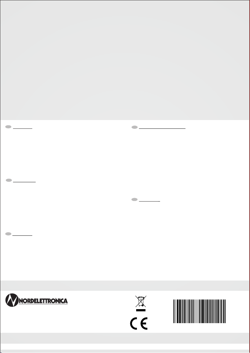
(1) RE1 disabled if J14-J15 jumper is present
61
21 3
8
5
2
7
1
4
9
3
6
5
8
4
7
6
9
1110 12
4
1
JP11
JP9
JP5
JP2
JP3
RE1
RE6
RE3 RE2 RE8
RE4
1
2
4
3
124
3
J2
JP1
JP4
124
3
B2 B1
J1
J3
-
J4 J5
JP16
1
2
4
3
1
JP8
2
1
JP14
RE9
2
1
JP15
JP13
3
12
6
45
J14 J15
RE10
JP7
1
BATTERY
CONTROL PANEL
CAR
40A
IN°C
OUT°C
2/4
0
1/4
S1
3/4
0
FULL
R2
R1
0
FULL
BATTERY
SERVICE
40A
1 1 1
2 1 43 121 2 910 11
4 35 6
83
JP2 JP5
F8F9 F7
RE3 RE6
2 14
4
3
21 1
JP4 J4JP3
F2F4F3
RE4
7
RE2RE8
F6F5
211 2
JP15JP14
RE9
2 1
JP16
3 4
F1
J2
1
JP1
3 4 8 965 721 1
J1 J3
1
PUMP
LIGHT
OUT
LIGHT
IN
1
J5
15A
15A
15A
10A
10A
30A
15A
20A
5A
JP11 JP9
1
2
543
S1 1/4
S1 2/4
S1 3/4
6
VE
2 134
R2 FULL
2 1
R1 FULL
NE185_20G
JP8 JP7
2 134
0,5A
JP13J14
1
J15
1
CHK_DC/DC
MiniFit JR
6vie (molex) screw
5MA Mate-N-Lok 9vie
Term: male screw
5MA screw
5MA LUMBERG
4vie MODU II
6vie (AMP) MODU II
4vie (AMP) MODU II
2vie (AMP)
FF 4,8x0,8
male
465 1 2 3
D+_NEG
- SM
KEY-ON
G
230V
RE1
PTC 2A RE10 230V
D+_NEG
KEY-ON &
G
KEY-ON &
(1)
HSD 0,5A
D+_NEG
KEY-ON &
G
KEY-ON &
D+_NEG
KEY-ON &
G
KEY-ON &
SIDE MARKER
KEY-ON
D+
G1A
5 6 4 21 3
1 1
DC/DC
PRESENT
BATTERY
CHARGER
Mate-N-Lok 12vie
Term: male RAST 5 red
4vie (molex) RAST 5 green
4vie (molex) RAST 5 white
4vie (molex) MiniFit JR
2vie (molex)
FF 6,3x0,8
male
RAST 5 black
4vie (molex)
+ SM
S1 4/4
4/4
-SM
+SM

15
JUMP
D+
1
2
34
S1 S2
DC/DC
CONVERTER
MOD. NE325
IN OUT
LIN
D+
30A
DC / DC NE325
+
-12V +-
12V
CAR
BATTERY SERVICE
BATTERY
NE355 DC/DC CONVERTER CONNECTION
61
21 3
8
5
2
7
1
4
9
3
6
5
8
4
7
6
9
1110 12
4
1
JP11
JP9
JP5
JP2
JP3
RE1
RE6
RE3 RE2 RE8
RE4
1
2
4
3
124
3
J2
JP1
JP4
124
3
B2 B1
J1
J3
-
J4 J5
JP16
1
2
4
3
1
JP8
2
1
JP14
RE9
2
1
JP15
JP13
3
12
6
45
J14 J15
RE10
JP7
1
RE5
NE185_20G 95.0001.321 Rev. 0
Viale delle Industrie 6A - ITALY
31018 Z.I. ALBINA DI GAIARINE (TV)
Tel.+39 0434 759420
www.nordelettronica.it
GARANZIA: NORDELETTRONICA riconosce un periodo di
garanzia di 2 (due) anni su tutti i suoi prodotti elettronici in rispetto alla
Direttiva Comunitaria 1999/44/CE recepita con Decreto Legislativo
24/2002. Sono esclusi dalla garanzia guasti o danni causati da:
Uso inadeguato e inappropriato del prodotto o impiego per uno scopo
diverso da quello previsto normalmente e sotto inosservanza delle relative
istruzioni per l’uso, negligenza, imprudenza o imperizia nell’installazione e
nell’uso
(NORDELETTRONICA declina ogni responsabilità per danni a cose o
persone), manutenzioni e/o riparazioni effettuate da personale esterno o
non direttamente autorizzato da NORDELETTRONICA.
I prodotti senza diritto o fuori garanzia verranno esclusivamente
riparati a carico del cliente (spese di trasporto e riparazione).
GUARANTEE: NORDELETTRONICA grants a guarantee period of
2 (two) years on all its electronic products (in application of EU Directive
1999/44/CE. The guarantee excludes faults or damage to products
originating from: unsuitable or inappropriate use of the product or its
employment for a purpose different from its usual one
(NORDELETTRONICA declines all responsability for damage to people or
things), or failure to observe the instructions for use provided by
NORDELETTRONICA, negligence, carelessness or unskilled practice in
installation and use, maintenance and/or repairs carried out by external
personnel or not authorized directly by NORDELETTRONICA.
Inapplicable products or those not covered by the terms of the
guarantee shall be repaired exclusively at the customer's expense
(transport and repairs).
GARANTIE : Tous nos produits électroniques NORDELETTRONICA
sont garantis deux ans conformément à la Norme Communautaire
1999/44/CE. Les pannes ou les dommages imputables aux cas de figure
ci-dessous sont hors garantie :
usage impropre et inadéquat du produit ou utilisation autre que celle pour
laquelle le produit a été fabriqué, non respect du mode d'emploi,
négligence, imprudence ou impéritie lors de l'installation et à l'usage.
NORDELETTRONICA décline toute responsabilité dans le cas de
dommages à des personnes ou à des choses dans le cas de
maintenance effectuée par des tiers non expressément autorisés par elle.
Les réparations de produits non couverts ou hors garantie seront à
charge du client (frais de transport et réparation).
GARANTIE-BEDINGUNGEN: NORDELETTRONICA gewährt eine
Garantie für den Zeitraum von 2 (zwei) Jahren auf alle seine
elektronischen Produkte gemäß der Direktive der Europäischen
Gemeinschaft 1999/44/CE.
Von der Garantie ausgenommen sind Störungen und Schäden welche
durch folgendes entstanden sind:
Unsachgemässiger und ungeeigneter Einsatz des Produktes oder
Gebrauch für andere Zwecke als normalerweise vorgesehen und/oder
Nichtbeachtung der Gebrauchsanweisungen, Leichtfertigkeit,
Unvorsichtigkeiten im Einbau und in der Benutzung.
NORDELETTRONICA weist jegliche Verantwortung zurück für
entstandene Schäden an Sachen oder Personen welche durch Reparatur-
und Unterhaltsarbeiten entstanden sind, die von Personal verursacht
wurden, welches nicht explizit und direkt von NORDELETTRONICA dazu
beauftragt wurde.
Produkte ohne Garantieanspruch oder ausserhalb des Garatie-
Zeitrahmens liegend werden ausschliesslich zu Lasten des Kunden
repariert (Reparatur und Transportkosten).
GARANTÍA: NORDELETTRONICA reconoce un periodo de
garantía de 2 (dos) años en todos sus productos electrónicos según la
Directiva Comunitaria 1999/44/CE. Se excluyen de la garantía averías o
daños causados por:Uso inadecuado e inapropiado del producto o uso
para un fin distinto de lo que está previsto normalmente, no observancia
de las correspondientes instrucciones de uso, negligencia, imprudencia o
impericia durante la instalación o el uso
(NORDELETTRONICA declina toda responsabilidad por daños a cosas o
personas), mantenimientos y/o reparaciones efectuados por personal
exterior o no directamente autorizado por NORDELETTRONICA.
Los gastos de reparación de productos sin derecho o fuera de
garantía estarán exclusivamente a cargo del cliente (gastos de
transporte y reparación).
E
D
F
GB
I
This manual suits for next models
1
Table of contents
Languages:
Other Nordelettronica Power Supply manuals


Popular Power Supply manuals by other brands

GILBARCO VEEDER-ROOT
GILBARCO VEEDER-ROOT M00016K003 installation manual

METRObility Optical Systems
METRObility Optical Systems ACPS-17HS Installation and user guide

Elmdene
Elmdene LPS-12-G2 Installation & user manual

GW Instek
GW Instek PEL-3021 user manual

EVEBASE
EVEBASE MOVE 1200 user manual

Paradyne
Paradyne 9000 Series installation instructions


